


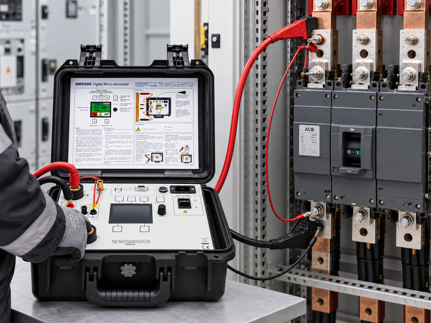
During maintenance of a three-pole circuit breaker, the contact resistances of all three poles are measured. Pole L1 shows 42 µΩ, L2 44 µΩ and L3 initially 71 µΩ. After repositioning a measuring clamp on L3, the measured value suddenly drops to only 47 µΩ. Has the contact resistance of the circuit breaker changed – or was the measurement simply not reproducible?
With circuit breakers, the resistances to be assessed are often in the micro-ohm range. The actual voltage drop across the closed contact is therefore very small. Contact resistances at measuring clamps, lead resistances and a changed position of the sense connections can have a significant influence on the measurement result.
For this reason, the four-wire or Kelvin method is used for such measurements. A defined DC current flows through the circuit-breaker pole under test. Two separate voltage leads measure the voltage drop directly across the defined measuring section. The resistance is then calculated from the test current and voltage drop.
For a reliable contact-resistance measurement, not only a sufficiently accurate micro-ohmmeter and a high test current are important. Clearly defined measuring points, reproducible contacting and identical test conditions for comparative measurements are equally essential.
Why is the contact resistance of a circuit breaker measured?
A closed circuit breaker should conduct the operating current with the lowest possible electrical resistance.
Ideally, the following should have only a very low total resistance:
- main contacts,
- moving contact connections,
- terminals and
- internal current paths.
An increased resistance causes additional power loss when current flows.
In simplified form:
P = I² × R
This means that even a relatively small increase in resistance becomes significant at high operating currents.
Increased contact resistance can indicate, among other things:
- worn contacts,
- contact erosion,
- oxidation,
- contamination,
- reduced contact force,
- mechanical misalignment or
- problems in the internal current path.
However, the resistance value alone does not provide a complete diagnosis. Design, manufacturer limits, comparison values and historical measurements must also be taken into account.
Why is a four-wire measurement required?
In a conventional two-wire measurement, the measuring current flows through the same leads used to measure the voltage.
As a result, the measurement includes additional contributions from:
- resistance of the measuring leads,
- resistance of the connection clamps,
- contact resistance at the measuring points.
For a resistance of, for example, only:
50 µΩ
these additional resistances would be far too large to simply ignore.
In a four-wire measurement, two separate current connections and two separate voltage connections are therefore used.
The test current flows through the current leads:
I+ → device under test → I-
The voltage is measured separately:
V+ → defined measuring section → V-
Since only a very small measuring current flows through the voltage leads, their lead resistance has only a negligible influence on the measured voltage drop.
The contact resistance is then calculated from:
R = U / I
What role does the test current play?
A micro-ohmmeter sends a defined test current through the closed contact path.
For the same resistance, a higher test current produces a larger voltage drop.
Example:
At:
R = 50 µΩ
and:
I = 10 A
the voltage drop is:
U = 0.5 mV
At:
I = 100 A
the voltage drop is:
U = 5 mV
A sufficiently high and stable test current therefore generally improves the measurability of very low resistances.
However, the test current must not simply be selected according to the principle “the higher, the better”.
The following are decisive:
- manufacturer specifications for the circuit breaker,
- test instructions,
- permissible loading of the device under test,
- micro-ohmmeter being used,
- measuring leads and connections.
For recurring comparative measurements, the same test current should be used wherever possible.
Where should the current and sense leads be connected?
The measured resistance always refers to the section between the two voltage contacts.
The position of the sense leads is therefore decisive.
If the voltage connections are placed at different points during a repeat measurement, a different part of the current path may be included in the measurement.
For reproducible results, the following should therefore be clearly defined:
- current connection points,
- sense connection points,
- the same contact surfaces for every measurement,
- documented connection positions.
The sense connections are generally positioned within the current path supplied by the high-current leads.
This ensures that the voltage measurement specifically captures the required resistance section.
Why must the contacting be reproducible?
With resistances in the micro-ohm range, even small changes in contacting can become visible in the measurement result.
A clamp can, for example, be placed on:
- an oxidized surface,
- paint,
- dirt,
- the edge of a bolt or
- a clean, bare metal surface.
Even though the sense lead itself carries virtually no significant test current, poor contacting can result in an unstable voltage signal.
For repeat measurements, the following should therefore be ensured:
- the same measuring points are used,
- the clamps are fully seated,
- the contact surfaces are clean,
- the leads do not mechanically pull on the clamps.
An abnormal resistance value should always be confirmed before a technical assessment of the circuit breaker is derived from it.
Why are measuring-lead resistances not included in Kelvin measurements?
The high-current leads naturally have their own electrical resistance.
At 100 or 200 A, this causes a clearly measurable voltage drop.
The decisive factor, however, is that this voltage drop lies outside the two sense points.
The micro-ohmmeter measures only the voltage:
between V+ and V-
and not the total voltage required to generate the test current.
This makes it possible to measure a very low resistance at the device under test accurately even with high-current leads several metres long – provided that the test instrument can actually supply the required test current through the complete circuit.
Why should the poles be compared with one another?
A three-pole circuit breaker provides three technically very similar current paths.
This enables a particularly useful plausibility comparison.
Example:
| Pole | Contact resistance |
|---|---|
| L1 | 43 µΩ |
| L2 | 45 µΩ |
| L3 | 79 µΩ |
The absolute value of 79 µΩ must not automatically be classified as unacceptable without reference to the manufacturer’s limits.
However, the clear difference compared with L1 and L2 is a useful reason for further testing.
The L3 measurement should first be repeated using identical measuring points and the same test current.
If the deviation remains, the current path should be investigated more closely.
What influence does temperature have?
The electrical resistance of metallic conductors is temperature-dependent.
If a circuit breaker is measured immediately after carrying a high current, its internal conductors and contacts may be warmer than during a later comparison measurement.
This can change the measured resistance even though the mechanical condition of the contact has not changed.
For trend measurements, comparable thermal conditions are therefore advisable wherever possible.
The following should be documented, for example:
- ambient temperature,
- operating condition before the measurement,
- where applicable, the temperature of the circuit breaker.
This can significantly improve interpretation, especially when assessing small changes over several maintenance intervals.
When should the measured value be read?
After the test current is switched on, a stable current and voltage value should first be reached.
A value read immediately while the test current is still rising is less suitable for a reproducible comparative measurement.
The test instrument should therefore indicate or confirm that:
- the required test current has been reached,
- the current is sufficiently stable,
- the sense voltage is stable,
- there is no obvious contacting problem.
For recurring tests, the measurement duration or time of reading should also be kept as comparable as possible.
What must be considered with circuit breakers grounded on both sides?
When working on high-voltage systems, a circuit breaker may be grounded on both sides for safety reasons.
This creates an additional parallel path for the test current through the grounding connections.
Part of the injected test current can then bypass the circuit breaker itself.
If the micro-ohmmeter simply used the total output current to calculate the resistance, the result could be distorted.
For such test arrangements, systems can be used that separately determine the current actually flowing through the contact path under test.
The DMO200 can optionally use a DC current clamp for this purpose. This allows the current flowing through the grounding connection to be taken into account.
A measurement on circuit breakers grounded on both sides must only be carried out according to the procedure specified for the system, test instrument and safety organization.
Practical example: one pole shows a significantly higher resistance
During maintenance of a three-pole circuit breaker, all three poles are measured using the same test current of, for example:
100 A DC
.
The initial results are:
| Pole | Measurement 1 |
|---|---|
| L1 | 41.8 µΩ |
| L2 | 43.1 µΩ |
| L3 | 68.7 µΩ |
L3 is clearly noticeable.
Before the circuit breaker is classified as defective, the measuring connections are checked.
The sense clamp on one side of L3 is partly positioned on an oxidized connection surface.
After cleaning the intended measuring point and establishing reproducible contacting, the measurement is repeated:
L3 = 44.2 µΩ
A third repeat measurement gives:
44.0 µΩ
The initially abnormal value was therefore not reproducible.
This example shows why, in micro-ohm measurements, not only the displayed numerical value but also the quality and repeatability of the contacting must be assessed.
Why are trend measurements often more informative than individual values?
A single contact-resistance value provides only a snapshot.
The measurement becomes particularly valuable when results are documented over several maintenance intervals under comparable conditions.
For example:
| Maintenance | L1 | L2 | L3 |
|---|---|---|---|
| 2024 | 42 µΩ | 43 µΩ | 42 µΩ |
| 2025 | 43 µΩ | 44 µΩ | 46 µΩ |
| 2026 | 43 µΩ | 44 µΩ | 58 µΩ |
Even if 58 µΩ is not automatically outside a manufacturer limit, the development of L3 shows a clear change.
For meaningful trend analysis, however, the following must be kept comparable:
- the same measuring points,
- the same test current,
- comparable temperatures and
- a comparable switching condition.
Systematically diagnosing increased contact resistance
- Do not immediately interpret the measured value as a device fault.
- Check the test current.
- Check the current leads for secure contact.
- Check the sense leads at the defined measuring points.
- Inspect the contact surfaces for oxidation or contamination.
- Repeat the measurement under identical conditions.
- Compare the other poles of the circuit breaker.
- Refer to previous maintenance measurements.
- Take temperature conditions into account.
- Check manufacturer limits or maintenance instructions.
- If the resistance remains reproducibly high, investigate the mechanical contact path.
Systematic test procedure
- Isolate and secure the system in accordance with the applicable safety rules.
- Clearly identify the device under test.
- Set the circuit breaker to the switching state specified for resistance measurement.
- Check the manufacturer’s test instructions and permissible test current.
- Define the current connection points.
- Define and document the sense measuring points.
- Connect the high-current leads securely.
- Connect the sense leads within the current path.
- Set the required test current.
- Switch on the test current and wait for stabilization.
- Document test current, sense voltage and resistance.
- Repeat the measurement if results are abnormal.
- Test all poles under comparable conditions.
- Compare the results with manufacturer values and historical measurements.
- Document measuring points and test current for the next maintenance interval.
Common measurement errors
- Using a two-wire measurement: Lead and contact resistances distort the micro-ohm value.
- Positioning the sense connections differently for each measurement: A different section of the current path is then measured.
- Failing to document the test current: Repeat measurements become less comparable.
- Selecting the test current arbitrarily high: Manufacturer and test-instrument specifications are decisive.
- Using oxidized or contaminated measuring surfaces: The sense signal can become unstable.
- Mechanically loading the clamps with the measuring leads: The contacting can change during the measurement.
- Recording only one abnormal individual value: Abnormal results should be reproduced.
- Ignoring pole comparison: The other poles provide valuable plausibility information.
- Ignoring temperature differences in trend measurements: Metallic current paths have a temperature coefficient.
- Ignoring the parallel current path with grounding on both sides: Part of the test current can bypass the actual contact section.
- Reading the value immediately after switching on the test current: Current and sense voltage should first be sufficiently stable.
- Replacing manufacturer limits with blanket micro-ohm values: Permissible values are circuit-breaker- and manufacturer-specific.
DMO200 for high-current micro-ohm measurements
A specific test instrument for contact-resistance measurements on circuit breakers is the DMO200 Digital Micro-ohmmeter.
The instrument generates an adjustable DC test current of:
1 ... 200 A DC
and enables resistance measurements in the very low resistance range.
The resolution is up to:
0.1 µΩ
Test current, sense voltage and resistance can be displayed simultaneously.
The DMO200 is particularly suitable for contact-resistance measurements on:
- circuit breakers,
- disconnectors,
- switchgear panels,
- grounding connections,
- busbar connections.
For recurring test tasks, test currents can be preset. Results can also be stored on a USB memory device and documented with time, date and comment information.
Optional Kelvin clamps and various extension cables are available.
For measurements on suitable devices grounded on both sides, an optional DC current clamp can also be used.
Further information can be found under DMO200 Digital Micro-ohmmeter and under resistance measuring instruments / micro-ohmmeters at ICS Schneider.
Conclusion
Contact-resistance measurement on a circuit breaker is a micro-ohm measurement in which even small differences in the test setup can have a significant influence on the result.
The four-wire or Kelvin method separates the high-current path from the voltage measurement and therefore prevents the resistance of the measuring leads from being included in the actual result.
For reproducible measurements, however, the current and sense connections must be clearly defined. If the voltage connections are moved during a repeat measurement, the resistance section being measured can also change.
The test current should be selected according to the manufacturer’s specifications or test instructions and kept constant for trend measurements. A high test current generally improves the measurable voltage, but it must not be selected without regard to the device under test.
Comparison between the poles and analysis of historical measured values are particularly valuable. A single absolute micro-ohm value is often less informative than a reproducible change compared with previous tests.
For reliable results, the following therefore applies: use a suitable test current, apply the four-wire method consistently, clearly define current and sense measuring points, reproduce abnormal values and document the measurement results under comparable conditions.
FAQ: Measuring contact resistance of circuit breakers
Why is the contact resistance of a circuit breaker measured?
Increased resistance can indicate changes in the contact or current path and can lead to additional power loss and heating.
Why is a normal multimeter not sufficient?
Contact resistances of circuit breakers are often in the micro-ohm range. Lead and contact resistances in a conventional two-wire setup can be larger than the actual resistance being tested.
Why is the four-wire method used?
Two leads carry the test current and two separate leads measure the voltage drop directly across the defined test section. This largely removes the resistance of the high-current leads from the measurement result.
Which test current should be used?
The appropriate test current depends on the circuit breaker, the manufacturer’s instructions and the test procedure being used. For reproducible trend measurements, the same defined test current should be used.
Is the highest possible test current always better?
No. A higher test current does produce a larger measurable voltage drop, but it must remain within the permissible conditions of the test instrument, measuring leads and device under test.
Where are the sense leads connected?
They are connected at the defined measuring points within the current path supplied by the high-current leads. Their position defines the resistance section actually being measured.
Why does the measured value change when a clamp is repositioned?
The contact quality may change, or the sense lead may then measure a slightly different section of the current path.
Should the three poles of a circuit breaker be compared with one another?
Yes. With comparable pole designs, pole-to-pole comparison provides a very useful plausibility check. A clear deviation of one pole should be reproduced and investigated.
Can temperature influence contact resistance?
Yes. Metallic conductors have temperature-dependent resistance. Trend measurements should therefore be carried out under comparable thermal conditions wherever possible.
Can a circuit breaker grounded on both sides be measured?
Depending on the test instrument and procedure, this is possible. It must be taken into account that part of the test current can flow through parallel grounding paths. The DMO200 offers an optional DC current clamp for this purpose.
Why are historical measured values important?
They show whether a current path changes over several maintenance intervals. An increasing trend can be significantly more informative than a single measured value without a comparison basis.
Which instrument is suitable for such measurements?
One specific example is the DMO200 Digital Micro-ohmmeter. It provides a DC test current from 1 to 200 A, offers 0.1 µΩ resolution and is designed for contact-resistance measurements on circuit breakers and other high-current connections.