


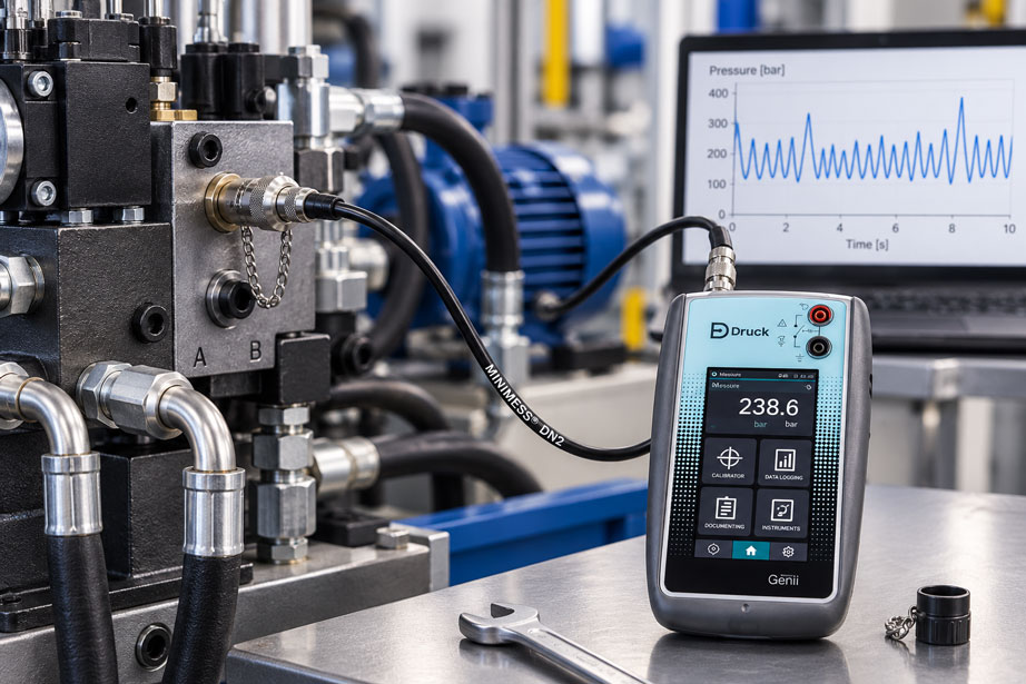
The pressure in a hydraulic system is to be measured during the running machine cycle. The normal operating pressure is, for example, 220 bar. A microbore hose is connected to an existing MINIMESS test point and linked to a digital pressure sensor or portable measuring instrument.
When the consumer is stationary, the measurement appears unremarkable. During machine operation, however, the pressure changes several times per second. In addition, short pressure spikes occur when a valve switches or when a cylinder decelerates. The hose and measuring coupling are therefore not subjected merely to a static pressure, but are continuously loaded and unloaded.
For selecting a MINIMESS measuring point, the specification “system pressure 220 bar” alone is therefore not sufficient. What matters is the actual minimum and maximum pressure, the magnitude of the recurring pressure swing and how many load cycles the measuring chain experiences during its service life.
At the same time, the measuring line itself has dynamic behaviour. A long microbore hose can damp or delay rapid pressure changes. The measurement may therefore appear smoother than the actual pressure loading directly in the hydraulic manifold.
The most important rule is therefore: In pulsating hydraulic systems, mechanical loading and measurement dynamics must be assessed separately. A MINIMESS hose with sufficient pressure resistance is not automatically the ideal measuring line for every rapid pressure profile – and an apparently low measured pressure peak does not automatically prove that the measuring point was subjected only to that pressure.
How does a MINIMESS measuring point work?
A MINIMESS test point provides compact access to a pressurised hydraulic system. When not coupled, an integrated valve element closes off the system connection.
When the suitable measuring coupling or measuring hose is connected, the internal valve mechanism opens and transfers the system pressure to the connected measuring chain.
A typical measuring chain consists of:
Hydraulic system → MINIMESS test point → measuring coupling → microbore hose → pressure sensor or pressure gauge
After the measurement is completed, the connection is disconnected again and the test point closes off the process connection.
The advantage is that no large process line has to be opened and no additional pressure gauge needs to be permanently installed in the machine for routine pressure measurements.
However, this does not mean that all components of the measuring point can be loaded without restriction. Test point, mating coupling, hose, fittings, adapters and measuring instrument each have their own pressure, temperature and media limits.
What does pulsating hydraulic pressure mean?
In many hydraulic systems, the pressure is not constant. Pumps, valves, cylinders and accumulators generate pressure conditions that change over time.
Typical causes include:
- delivery pulsations from a pump,
- rapid opening or closing of valves,
- cylinder movement and load changes,
- contact with a mechanical stop,
- pressure control and accumulator charging,
- periodic machine cycles.
The pressure may, for example, regularly fluctuate between:
80 bar ↔ 260 bar
.
In addition, a significantly higher peak may occur briefly during a valve switching event.
For the measuring point, therefore, it is not just a single average value that matters. It experiences the complete pressure history over time.
Why pressure cycles behave differently from static pressure
A component that is permanently subjected to 250 bar is in a different mechanical situation from a component that continuously cycles between low and high pressure.
With every pressure change, the mechanical stresses change in:
- the hose wall,
- the fittings,
- the metal body of the coupling,
- the valve elements,
- the sealing points.
Over time, this recurring load can contribute to fatigue, wear and changes in the sealing points.
When assessing a highly cyclic application, the pressure cycles should therefore be considered in addition to the operating hours.
A machine that runs only a few hours per day can still accumulate a very high number of cycles if several pressure changes occur every second of operation.
Distinguishing minimum pressure, maximum pressure and pressure amplitude
Several quantities are relevant to cyclic loading.
| Quantity | Example | Meaning |
|---|---|---|
| Minimum pressure | 50 bar | Lower pressure point of the recurring cycle |
| Maximum pressure | 300 bar | Upper regular pressure point |
| Pressure swing | 250 bar | Difference between low and high pressure |
| Short-term peak | 360 bar | Additional dynamic peak loading |
| Number of cycles | e.g. 500,000 | Number of recurring pressure load cycles |
Two applications with the same maximum pressure can therefore place different demands on the measuring point.
A system that continuously fluctuates between 280 and 300 bar has a much smaller pressure swing than a machine that cycles from almost 0 to 300 bar every time.
For component selection, the actual pressure profiles should therefore be known wherever possible, not just the nominal value set at the pressure relief valve.
Also consider short pressure spikes
Another critical factor is short pressure spikes.
They may occur, for example, due to:
- abrupt closing of a directional valve,
- sudden deceleration of a cylinder,
- load changes,
- hydraulic impact,
- unfavourable accumulator or valve settings.
Such events can be much shorter than the actual machine cycle.
An analogue pressure gauge or a slowly recorded trend may completely miss such a peak or display it only in a strongly attenuated form.
The permissible pressure loading of the measuring chain should therefore not be derived solely from a slowly measured operating pressure.
If unknown pressure spikes are suspected, a sensor and recording system must be used whose dynamic response is sufficient for this task.
The entire measuring chain must match the pressure
A MINIMESS measurement is only as robust as its weakest component.
In particular, the following should be checked:
| Component | Property to check | Typical source of error |
|---|---|---|
| Test point | Pressure, temperature, medium, thread | Wrong series or aged seal |
| Mating coupling | Compatibility and pressure rating | Incompatible coupling series |
| Microbore hose | Working pressure, temperature, age and condition | Kink, abrasion or ageing |
| Hose fitting | Pressure rating and mechanical condition | Damage or tensile load |
| Adapter | Pressure rating and sealing principle | Unsuitable adapter combination |
| Pressure sensor | Measuring range and permissible overload | Measuring range selected too narrowly |
| Data logger | Sampling rate and channel bandwidth | Pressure peak is not recorded |
Specifying a permissible pressure for the test point alone therefore does not automatically mean that the entire temporary measuring chain may be operated at that pressure.
The lowest permissible limit of any component involved determines the maximum permissible loading of the complete setup.
How pressure cycles load the measuring hose
During a pressure measurement, the MINIMESS microbore hose is part of the pressure-bearing system.
With every increase in pressure, the hose attempts to expand slightly. When the pressure falls again, this elastic deformation is reversed.
With a very high number of pressure changes, this results in repeated mechanical loading of the hose construction and fittings.
Additional influences can include:
- vibration,
- bending movement,
- abrasion against machine components,
- tensile load on the connection fittings,
- high media temperature,
- UV exposure and ageing effects.
A hose can therefore be mechanically more heavily loaded than an externally almost identical hose that is used only occasionally for static pressure measurement.
Inspection and replacement intervals should therefore be defined more conservatively for strongly pulsating applications.
Coupling, valve and seals as wear points
The MINIMESS test point itself is also more than a rigid threaded connection.
When coupling and uncoupling, the internal valve is actuated mechanically. Seals and contact surfaces are subjected to load.
During operation, the following additionally act on the measuring point:
- system pressure,
- pressure changes,
- temperature,
- medium,
- vibration.
A measuring point may therefore initially appear completely leak-tight when closed and still become noticeable during the next coupling operation.
Before each measurement, visible sealing surfaces, coupling, threads and connection areas should be inspected for damage and contamination.
A stiff or damaged coupling should not be made “operable” by applying additional force.
Evaluate pressure, temperature and medium together
The permissible pressure loading must not be considered independently of temperature and medium.
A hose or seal may be suitable for a particular pressure at room temperature but have different permissible operating conditions at significantly higher temperatures.
High temperatures can also accelerate ageing of polymer hose and sealing materials.
The following must therefore be compatible when selecting components:
Pressure + temperature + medium + pressure cycles + duration of use
This applies to the entire measuring chain.
An FKM sealing element in the test point, for example, does not automatically make a standard measuring hose suitable for the same high temperature.
The hose material must likewise be compatible with the actual hydraulic medium.
Why the MINIMESS hose can alter pressure pulsations
During a static measurement, practically the same pressure establishes itself in the closed measuring hose as at the test point after sufficient time.
With rapid pressure changes, the situation is different.
The measuring line has:
- a certain internal volume,
- hydraulic flow resistance,
- an elastic hose wall,
- a fluid with finite compressibility.
This creates a hydraulic transmission system with its own dynamic behaviour.
A very rapid pressure peak may therefore appear at the sensor:
- later,
- wider,
- with a lower amplitude.
This effect is particularly important for diagnostics. A microbore hose can behave like a hydraulic low-pass filter.
The question “Is the hose pressure-resistant enough?” is therefore a different question from “Does the hose transmit the required pressure profile with sufficient fidelity?”
Avoid air bubbles in the measuring line
Trapped air has a particularly strong influence on dynamic pressure measurement.
Hydraulic oil is only slightly compressible compared with air. Even a small gas bubble therefore introduces additional elastic volume.
This can cause:
- greater damping of pressure changes,
- signal delays,
- changes in natural oscillations,
- poorer reproducibility of comparison measurements.
For dynamic measurements, the measuring line should therefore be filled with the medium according to the intended procedure and be free of relevant gas bubbles.
A pressurised fitting must not simply be loosened in order to supposedly “bleed off some air”.
The designated connections and operating procedures must be used for venting and pressure relief.
Choose the hose length to suit the measurement task
A longer line offers practical advantages during service work. The measuring instrument can be positioned safely and visibly outside a confined or heavily vibrating machine area.
For very fast pressure measurements, however, a long line is often less favourable.
As the length increases, so do:
- the enclosed fluid volume,
- the hydraulic resistance,
- the influence of hose elasticity.
For a simple operating-pressure check, a longer MINIMESS line can be perfectly suitable.
For targeted investigation of:
- valve shocks,
- pump pulsations,
- short pressure surges,
- rapid control processes
the connection should instead be made as short and as well defined as is reasonable for the specific measurement.
For comparison measurements, the same hose configuration should also be retained wherever possible.
Select the pressure sensor and measuring range correctly
A pressure sensor should not be selected solely according to the normal operating pressure.
Example:
The system normally operates at:
220 bar
Known load changes reach:
310 bar
Additional short peaks that have not yet been reliably quantified may also occur.
A sensor whose measuring range ends only slightly above 220 bar would be unsuitable for this diagnostic task.
The measuring range and permissible overload are two different specifications.
The overload limit is not an extension of the normal measuring range. A sensor should operate within its specified measuring limits during normal measurement.
At the same time, the measuring range should not be selected unnecessarily large if this would reduce the resolution required for smaller pressure changes.
Distinguish sampling rate from measurement dynamics
Even an excellent pressure sensor is of little use if the data logger records too slowly.
In dynamic measurements, several components jointly determine the usable bandwidth:
Hydraulic system → test point → hose → sensor → electronics → data logger
A higher sampling rate can make a rapidly changing pressure peak more visible if the signal reaches the sensor accordingly.
However, it cannot recover a peak that has already been strongly damped hydraulically by a long or air-filled measuring line.
Conversely, an extremely short hose is of little benefit if the data logger stores only a few measured values per second.
For meaningful pulsation measurement, hydraulic and electronic measurement dynamics must therefore be considered together.
Inspect the hose and coupling before measurement
Before every measurement, the temporary measuring line should be subjected to a visual and functional inspection.
In particular, check for:
- cracks and abrasion marks,
- blisters or local bulging,
- kinks,
- damaged protective layers,
- corrosion on fittings,
- damaged threads,
- contaminated coupling surfaces,
- damaged or crushed seals.
The routing of the hose during measurement should also be checked.
The hose should not:
- rub against sharp edges,
- be excessively tensioned,
- lie directly against hot components,
- run between moving machine parts.
With a pulsating line, vibrations can additionally cause mechanical movement of the hose and fittings.
Define replacement intervals according to loading
Using the same replacement interval for all MINIMESS hoses is not particularly useful.
The actual loading can vary considerably.
A hose used only a few times a year at room temperature for short static measurements ages under very different conditions from a line permanently installed on a test bench and subjected to hundreds of thousands of pressure changes every day.
When defining inspection and replacement intervals, the following should therefore be considered, among other factors:
- manufacturer specifications,
- hose material,
- maximum pressure loading,
- pressure amplitude,
- pressure cycles,
- temperature,
- medium,
- vibration and movement,
- UV and environmental influences,
- consequences of a possible hose failure.
Inspection intervals should be shortened accordingly under heavy dynamic loading.
A hose of unknown age and unknown history should not continue to be used solely because it appears externally undamaged.
Safe service practice with pulsating pressure
MINIMESS test points allow the designated connection of a suitable measuring line to a pressurised system. This must not be interpreted to mean that arbitrary work on the measuring point may be carried out under pressure.
In particular, the following should not be carried out under pressure:
- removing the permanently installed test point,
- loosening adapters,
- replacing damaged components,
- tightening a leaking threaded connection
.
Such work must be carried out with the system in a safe and depressurised condition in accordance with the applicable operating procedure.
During measurement, the hose should be routed so that people are, as far as possible, outside the area of potential hose movement or a possible fluid jet.
A visible leak in a high-pressure hydraulic system must not be searched for or felt by hand.
Practical example on a cyclic hydraulic system
The pressure of a hydraulic cylinder on an automated machine is investigated via a MINIMESS test point.
The normal working pressure is:
210 bar
The PLC records a relatively smooth profile between:
190 and 230 bar
.
Nevertheless, strong mechanical load changes are noticeable on the machine.
For a more detailed diagnosis, a suitable fast pressure sensor is connected via the existing MINIMESS connection.
Initially, a long service hose is used. The recording shows:
Maximum ≈ 255 bar
The pressure rise appears relatively smooth.
For a second comparison measurement, the hydraulic measuring connection is significantly shortened in accordance with the intended measurement setup, and care is taken to ensure a reproducible condition free of air.
For the same machine event, the measurement now shows a significantly steeper pressure profile and, for example:
Maximum ≈ 315 bar
The values are for illustration only.
The diagnosis provides two important findings:
Firstly, the actual dynamic pressure loading was higher than was apparent from the original measurement.
Secondly, the temporary measuring chain must be suitable not only for the nominal working pressure of approximately 210 bar, but also for the pressure peaks and load cycles that actually occur.
For future tests, a distinction is therefore made between a conveniently routed service line for static checks and a defined short measuring setup for dynamic pressure analyses.
Systematically check implausible measured values
If pressure measurements are unusual or poorly reproducible, the sensor should not immediately be assumed to be the cause.
| Observation | Possible cause | Sensible check |
|---|---|---|
| Pressure curve appears unusually smooth | Long measuring hose or air in the line | Check the hydraulic measuring connection |
| Peak does not increase with a higher sampling rate | Hydraulic damping upstream of the sensor | Check hose length and freedom from air |
| Measured value jumps after the hose is moved | Kink, gas bubble or contact problem | Check hose and connections |
| Unusually large amount of oil escapes during coupling | Seal, valve or coupling damaged | Take the measuring point out of service and inspect it |
| Hose shows a blister or local bulging | Hose damage | Do not continue using it |
| Measurement changes significantly with oil temperature | Viscosity, hose dynamics or sensor behaviour | Compare temperature and the complete measuring chain |
Especially in pulsating systems, a comparison with a second measuring configuration is useful. If the recorded pressure profile changes significantly with hose length or sensor position, the measuring chain itself is part of the observed dynamic behaviour.
Common mistakes
Considering only the normal operating pressure
Short pressure spikes and recurring load changes can place significantly greater stress on the measuring point than the displayed average value suggests.
Equating operating pressure with pressure-cycle resistance
A static pressure specification does not automatically describe service life under any arbitrary number of dynamic pressure cycles.
Checking only the test point
The hose, fittings, adapters and measuring instrument must also match the actual pressure profile.
Using a long hose for every dynamic measurement
A long microbore hose can damp short pressure events and therefore lead to underestimation of the actual dynamics.
Ignoring trapped air
Air bubbles increase the compressibility of the measuring line and particularly affect rapid pressure signals.
Using the sensor overload limit as the normal measuring range
The overload specification is a protection limit, not an additional normal measuring range.
Assessing hose condition only according to operating hours
Pressure cycles, temperature, vibration, bending and environmental influences also determine the load.
Tightening a leaking connection while under pressure
A damaged or leaking connection must be investigated after the system has been safely depressurised using the prescribed procedure.
Automatically assuming the hose is depressurised after uncoupling
Residual pressure can remain in a measuring line if the medium is trapped between closed connections. Before further disassembly, the line must be depressurised via the designated pressure-relief path.
Suitable MINIMESS components at ICS Schneider
ICS Schneider Messtechnik offers MINIMESS test points, microbore hoses, adapters and complete measuring and service combinations for industrial and mobile hydraulic applications.
The MINIMESS Series 1620 with M16×2 coupling thread is used for numerous standard applications. Depending on the version, different process threads, materials and seals are available.
For more compact or different connection concepts, the 1215, 1615 and 1604 series are also available. The series are not freely interchangeable on the coupling side and must be selected to match the existing measuring point.
The MINIMESS microbore hoses are available, among other versions, in DN2 and DN4. Depending on the version, they differ in working pressure, hose material, fittings, temperature range and dynamic behaviour.
For pulsating hydraulic applications, at least the following information should be known when selecting components:
- minimum and maximum pressure,
- expected pressure spikes,
- frequency of pressure cycles,
- medium,
- medium and ambient temperature,
- required hose length,
- measurement task: static pressure or dynamic pressure profile.
MINIMESS couplings and hoses at ICS Schneider
Further reading: Using MINIMESS test hoses safely
Further reading: Pressure measurement via microbore hose responds too slowly
Conclusion
A MINIMESS measuring point on a pulsating hydraulic line must be assessed differently from a purely static service measurement.
Not only the maximum operating pressure, but also pressure amplitude, pressure spikes, number of load cycles, temperature and mechanical loading determine the stress on the test point, hose and fittings.
At the same time, the measuring line itself influences the recorded pressure profile. A long microbore hose, trapped air or a large connection volume can damp rapid pressure changes. An apparently low pressure peak is therefore not automatically identical to the actual peak directly in the hydraulic manifold.
For reliable diagnostics, two questions must therefore be answered separately:
Is the measuring chain mechanically suitable for the actual pressure loading?
and:
Is the measuring chain dynamically fast enough to reproduce the required pressure profile correctly?
Anyone who also regularly checks hose condition, seals and couplings and adapts inspection and replacement intervals to the actual cyclic loading improves both measurement quality and safety during temporary hydraulic measurements.
FAQ on MINIMESS on pulsating hydraulic lines
Can MINIMESS be used with pulsating hydraulic pressure?
MINIMESS test points are generally intended for pressure measurements on hydraulic systems. With pulsating loading, however, pressure range, pressure spikes, cycles, hose, seals and the specific measurement task must be taken into account.
Is it sufficient if the normal operating pressure is below the permissible hose pressure?
No. Short-term pressure spikes and cyclic loading must also remain within the permissible conditions for the specific measuring chain.
Why are pressure cycles important?
Every pressure change generates recurring mechanical loading of the hose, fittings, valves and seals. A high number of such load cycles can affect service life.
What is important in a pressure cycle?
Among other things, minimum pressure, maximum pressure, pressure swing, rate of pressure increase and number of cycles.
Can a MINIMESS hose damp pressure spikes?
Yes. Length, internal diameter, hose elasticity, medium and trapped air can influence the amplitude and time response of rapid pressure changes.
Is a longer hose always worse?
No. For normal service work and static pressure measurements, a longer line can be very practical. For very rapid pressure events, however, its influence on measurement dynamics must be considered.
Why are air bubbles in the measuring hose problematic?
Air is much more compressible than hydraulic fluid. This can cause pressure changes to be delayed and damped more strongly.
Can a higher sampling rate restore a damped pressure peak?
No. A higher sampling rate helps only with signals that are actually present at the sensor. If the peak has already been hydraulically damped, the data logger cannot reconstruct it afterwards.
How can I recognise a damaged MINIMESS hose?
Warning signs include cracks, blisters, local bulging, severe abrasion, kinks, damaged fittings or noticeable corrosion.
Can a hose with a small blister continue to be used?
No. A blister or local bulging indicates damage to the hose structure. The line should not continue to be used under pressure.
How often must a MINIMESS hose be replaced?
A universal replacement interval for all applications is not meaningful. Manufacturer specifications, age, pressure cycles, temperature, mechanical loading and operating conditions must be considered together.
Can a MINIMESS test point be connected under pressure?
The designated suitable measuring coupling can be connected to appropriate MINIMESS test points under pressure within the permissible operating conditions.
Can the permanently installed test point be removed under pressure?
No. Replacement, repair or work on the permanently installed connection must be carried out with the system safely depressurised in accordance with the operating procedure.
Which MINIMESS series is commonly found in standard hydraulics?
Series 1620 with M16×2 coupling thread is used in many industrial and mobile hydraulic applications. However, the existing measuring point must be identified unambiguously.
Which hose sizes are commonly used?
MINIMESS microbore hoses are available, among other versions, in DN2 and DN4. The appropriate version depends on pressure, flow requirements, length and measurement dynamics.
Why can a short hose be useful for dynamic measurement?
A shorter transmission path typically contains less fluid volume and has less hydraulic influence on very rapid pressure changes.
Does the pressure sensor have to be mounted directly on the MINIMESS test point?
Not necessarily. A hose can isolate the sensor from heat, vibration or inaccessible areas. For rapid pressure analysis, however, the influence of the hose must be taken into account.
What should be documented before a measurement?
At minimum, the measuring point, MINIMESS series, hose type and length, pressure range of the sensor, medium, temperature and – for dynamic investigations – sampling rate and expected pressure cycles.
Can pressure remain in the hose after uncoupling?
Yes. If the medium is trapped between closed connections, residual pressure can remain in the measuring line. Before further disassembly, the line must be depressurised through the designated route.