


An extruder appears to be running steadily. Barrel temperatures and heating bands are at their setpoints, the melt pressure is unremarkable and the temperature sensor, for example, constantly indicates 205 °C. Nevertheless, the product quality changes. The melt behaves differently than expected at the outlet, or laboratory values suggest that the polymer is actually hotter than the process indication suggests.
In such situations, the temperature sensor itself is often suspected first. However, comparison with a new sensor sometimes provides little clarity: after replacement, the same sensor type suddenly indicates several kelvin more or less.
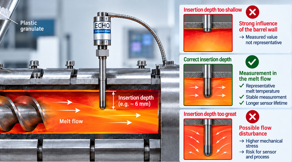
The cause does not necessarily lie in the accuracy of the thermocouple or Pt100. In melt temperature measurement, the mechanical position of the measuring point is an essential part of the measuring system. A difference of only a few millimetres in immersion depth can cause the sensor tip to measure a different zone of the melt flow.
This is particularly important in extrusion processes because the plastic melt is not necessarily perfectly thermally homogeneous. Temperature differences can exist between the heated barrel or adapter wall and the core of the melt flow. At the same time, additional heat is generated in the polymer through shear. The locally measured temperature therefore also depends on the radial position of the actual measuring point.
A sensor installed too shallowly can be influenced more strongly by the metal and boundary-zone temperature. A sensor inserted further into the process measures closer to the actual melt flow, but is also subjected to greater mechanical loads from pressure and flow. If the probe extends unnecessarily far into the channel, it can also influence the material flow or, with unfavourable orientation, be exposed to increased bending stress.
The most important rule is therefore: The immersion depth of a melt temperature sensor is not a minor installation parameter. Sensor tip, measuring bore, flow cross-section and measuring task must match each other. Only then does the displayed value actually represent the temperature zone that is relevant to the process.
Distinguishing melt temperature from metal temperature
The temperature indication of an extruder zone and the actual temperature of the plastic melt do not necessarily describe the same physical condition.
The barrel temperature is usually measured in or close to the metal wall of the machine. It is important for controlling the heating and cooling zones. Melt temperature, by contrast, describes the temperature of the moving polymer.
Relevant differences can occur between the two. The material absorbs heat from the barrel and heating system, while additional shear heating is generated by the mechanical processing. Cooling, throughput, screw speed, material viscosity and residence time also influence the temperature distribution.
A temperature sensor whose measuring point is effectively still located in the region of the metal wall can therefore provide a very stable and reproducible value without adequately representing the melt temperature that is relevant to product quality.
This is precisely where a typical source of error lies: the measured value is not obviously wrong. It may even be extremely stable. However, the measurement reflects the thermal environment of the measuring bore more strongly than the desired zone within the polymer flow.
Why the temperature can vary across the melt flow
The simplified idea of an extruder channel having exactly the same melt temperature everywhere does not always correspond to reality.
Close to the wall, the temperature-controlled metal surface has a stronger influence on the melt. Further inside, the temperature is determined more strongly by the material itself, its thermal history and the shear energy introduced into it. Depending on the extruder, tool, throughput and polymer, radial temperature profiles can therefore develop.
This means that two fully functioning sensors can indicate different temperatures if their measuring points are positioned at different locations in the cross-section.
The question “Which of the two sensors is measuring correctly?” may therefore be the wrong question. Both can be measuring correctly at their respective locations. They are simply not measuring the same zone.
When evaluating the process, it must therefore be clear which temperature is actually required. Is the melt close to the wall to be monitored? Is a representative core temperature required? Or should a temperature profile across the cross-section deliberately be determined?
Only the measuring task determines the appropriate position of the sensor tip.
What happens if the immersion depth is too small?
If a melt temperature sensor is installed too shallowly, the temperature-sensitive zone is too close to the measuring bore or metal wall.
This increases the influence of the surrounding temperature of the extruder barrel, adapter or tool. The sensor then does not measure the melt alone, but a thermal mixture of polymer, metal and heat conduction through the sensor body.
This becomes particularly problematic when the wall temperature and melt temperature differ significantly.
If, for example, the metal wall is cooler than the actual melt temperature, a sensor installed too shallowly can make the polymer flow appear too cold. If the wall temperature is higher, the opposite effect is also possible.
The result can appear entirely plausible from a process perspective while still being systematically shifted.
Another issue is dynamic behaviour. A measuring point strongly influenced by the wall can display real changes in melt temperature in a damped or delayed manner. The sensor may appear extremely stable because a massive metallic region has a strong thermal influence on the measuring point.
What happens if the immersion depth is too large?
More immersion depth is not automatically better.
As the sensor extends further into the melt flow, the direct influence of the metal wall often decreases. At the same time, however, the sensor tip is exposed more strongly to the actual process.
The melt exerts pressure and flow forces on the sensor. The further a slender probe projects freely into the flow channel, the greater the possible mechanical loading. Particularly with highly viscous polymers, high throughput or unfavourable probe geometry, bending stress can increase.
A probe that extends far into the flow can also become a local disturbance to the flow profile itself. This is particularly relevant when its cross-section is no longer negligible compared with the free melt channel.
The optimum immersion depth is therefore a compromise: far enough into the melt to measure the required material zone, but no further than is mechanically and fluid-dynamically sensible for the measuring task.
| Installation situation | Typical influence | Possible consequence |
|---|---|---|
| Sensor almost flush | Strong influence from wall and measuring bore possible | Melt temperature is not measured representatively |
| Small immersion depth | Measuring point still close to the boundary zone | Wall-temperature influence remains relevant |
| Suitable immersion depth | Measuring point is located in the desired melt zone | Reproducible process measurement |
| Unnecessarily large immersion depth | Higher mechanical loading and stronger possible influence on flow | Increased risk of damage or changed measuring conditions |
| Measuring point close to channel centre | Reduced direct wall influence | Suitable for certain profile and core-temperature measurements |
Know the actual measuring point of the sensor
When determining the immersion depth, it is not enough to consider only how many millimetres of the visible sensor stem project into the process.
The position of the actual temperature-sensitive element is decisive.
With thermocouples, the measuring junction is located where the two thermocouple wires are joined. Depending on the sensor design, this measuring point may be directly at the tip, slightly recessed or deliberately designed to be particularly exposed.
With resistance thermometers, the Pt100 element is likewise located within a defined region of the probe tip. The mechanical end of the sensor and the thermally active measuring point therefore do not necessarily coincide exactly.
This becomes relevant when replacing a sensor. Two temperature sensors may have the same thread and the same external insertion length, but due to their internal design they may have a slightly different thermal measuring position or different response behaviour.
For reproducible measuring points, “the thread fits” should therefore not be used as the sole replacement criterion.
Is an immersion depth of 6 mm always correct?
For conventional immersion thermocouples, an immersion depth of approximately 6 mm is often mentioned in extrusion practice as a useful guideline. The idea is to position the measuring tip sufficiently far away from the metal-dominated wall region and into the melt.
However, this value is not a universal installation dimension for every extruder.
A 20 mm melt channel, a large adapter and a narrow die opening have completely different geometries. The measuring task can also differ significantly.
In a very small flow opening, 6 mm may already represent a considerable proportion of the cross-section. In a large melt channel, by contrast, 6 mm may still be relatively close to the wall.
The suitable position must therefore be derived from the channel geometry, sensor design and desired measuring zone.
The 6 mm recommendation is therefore a useful technical guideline for classic installation situations, but not a rule that should be adopted without considering the actual extruder.
Use adjustable sensors to record temperature profiles
If it is unclear which immersion depth best represents the process, an adjustable measuring point can provide considerably more information than a sensor with a fixed length.
The Dynisco GRMT is designed specifically for this task. Its measuring point can be moved progressively from a flush position further into the hot polymer flow.
This allows the same process to be investigated at different radial measuring positions without requiring a separate sensor bore for every depth.
A typical profile might, for example, show:
2 mm immersion depth → 198 °C
6 mm immersion depth → 204 °C
12 mm immersion depth → 208 °C
18 mm immersion depth → 209 °C
These figures are examples only. The important point is their interpretation: such a profile would indicate that the zone close to the wall is cooler than the inner melt flow.
This makes it easier to determine which fixed sensor position will later be most useful for process monitoring.
Another extruder may show a completely different profile. This is exactly why variable measurement is so useful for process development, commissioning and troubleshooting.
Align blade-shaped sensors with the direction of flow
Not every melt temperature sensor has a simple round tip. Special designs use a blade-shaped measuring element that extends further into the melt.
Such a geometry can provide good thermal coupling to the polymer flow, but it must be installed in a flow-oriented manner.
If a narrow blade is positioned with its broad face perpendicular to the melt flow, greater flow forces occur than when it is aligned with the direction of flow. At the same time, the probe can influence the flow more strongly.
For this reason, the Dynisco DYMT version with temperature blade, for example, has a rotatable design. The blade can be aligned with the direction of flow.
This alignment is not only a question of service life. It also contributes to reproducible flow conditions at the measuring point.
If such a sensor is reinstalled after maintenance work, not only the immersion depth should therefore be checked. The angular position of the blade is also part of reproducible installation.
Consider measuring bore and insertion length together
The nominal length of a melt temperature sensor alone does not determine how far its measuring tip actually projects into the flow channel.
Adapters, threaded bores, sealing geometry and wall thickness may lie between the mounting surface and the melt channel. Only when these dimensions are known can the actual immersion depth be determined.
A replacement sensor with a 25 mm probe length may, for example, extend 6 mm into the melt in one machine but terminate almost flush in another design.
Particularly when sourcing replacements, the original sensor code or the actual installation geometry should therefore be known wherever possible.
Simply measuring the overall length of the old sensor is not always sufficient. Relevant dimensions include the reference point of the process thread, shoulder or sealing surface and the position of the measuring tip.
Deposits in the measuring bore can also alter the effective installation position or prevent the sensor from being screwed in completely.
Consider heat conduction through the sensor stem
A melt temperature sensor does not measure thermally isolated from its surroundings.
The metallic sensor stem connects the hot measuring tip to the process fitting and the part of the sensor located outside the process. Heat conduction therefore occurs along the sensor.
The magnitude of this effect depends, among other things, on material, diameter, design and immersion depth.
At small immersion depths, the measuring point is thermally coupled more strongly to the metal extruder wall. As the useful immersion depth increases, heat transfer from the flowing melt becomes increasingly important.
This explains why a sensor tip does not necessarily indicate the local melt temperature as soon as it projects only a few tenths of a millimetre visibly into the channel.
For good melt temperature measurement, the thermal coupling to the melt must be sufficiently dominant compared with interfering heat-conduction paths.
Immersion depth and response time
The position within the flow profile influences not only the steady-state temperature value but also the dynamic behaviour of the measurement.
A measuring point with good direct contact with the moving melt typically responds more clearly to real changes in material temperature than a measuring point strongly influenced by a massive metal wall.
The sensor design itself also plays a major role. A thin or exposed thermocouple junction responds more quickly than a massive protected construction, but is often mechanically more sensitive.
Sensor selection is therefore always a compromise between response time and robustness.
For long-term process monitoring, a robust version may be more suitable. For trials, material changes or investigations of rapid temperature changes, a faster measuring point may be more important.
When comparing different sensors, the steady-state value after a long stabilisation period should therefore not be the only factor considered. The response time to a real process change can also provide important information about the measuring point.
Melt pressure and mechanical loading
A melt temperature sensor operates not only at high temperature but often simultaneously under considerable process pressure.
The pressure initially acts on the pressure-loaded surfaces of the sensor. In addition, the highly viscous melt flowing past the sensor creates forces on any elements projecting into the process.
The further a slender probe extends into the channel, the greater the mechanically effective lever arm can become.
Permissible process pressure and probe geometry must therefore be considered together. A conventional laboratory temperature sensor is not automatically suitable for direct installation in an extrusion line.
Products designed for melt temperature measurement are specifically engineered for these operating conditions. Even so, a high permissible pressure rating does not mean that arbitrary immersion depths or installation orientations are mechanically sensible.
With highly abrasive or filled polymers, wear effects must also be considered. Glass fibres or mineral fillers can subject an exposed sensor tip to greater wear than an unfilled standard melt.
Barrel, adapter, die or tool?
Even a perfectly immersed sensor measures only the temperature at its particular process location.
A measurement in the extruder barrel describes a different point in the thermal process history from a measurement in the adapter, directly before a screen pack, after a melt pump or directly before the die.
The polymer may absorb additional shear heat or release heat to its surroundings between these locations.
When evaluating a measured value, the measurement position should therefore always be stated together with the temperature.
The statement “melt temperature 210 °C” is less precise from a process perspective than “210 °C in the adapter directly before the die”.
This point is also crucial when comparing different extrusion lines. Two machines can show the same measured value even though the sensors are installed at completely different process positions.
Document measuring points reproducibly
A melt temperature measurement becomes considerably more meaningful when its mechanical configuration is documented.
For a permanently installed sensor, at least the sensor type, installation position and relevant immersion depth should be known. For adjustable sensors, the set position should additionally be documented.
For blade-shaped sensors, the orientation relative to the flow can also be relevant.
This is particularly important for maintenance work. If a sensor is replaced after several months and the new sensor is installed five millimetres deeper, the indicated temperature may change even though the process and sensor accuracy have remained unchanged.
| Parameter to document | Why is it important? | Typical consequence of deviation |
|---|---|---|
| Sensor type | Determines measuring element and construction | Different response or heat-conduction behaviour |
| Installation position | Defines the process location | Different actual melt temperature |
| Immersion depth | Defines the radial measuring position | Different wall or core influence |
| Sensor-tip geometry | Influences heat transfer and flow | Different dynamics and mechanical loading |
| Orientation | Relevant to flow with blade probes | Changed loading and flow conditions |
| Thermocouple type / Pt100 | Must match the evaluation electronics | Systematic signal error possible |
This turns a simple temperature value into a traceable measuring point.
Practical example: same sensor, different measured value
An older melt temperature sensor is replaced on an extruder. Before replacement, the measuring point indicated approximately 202 °C during stable production.
The new sensor has the same thermocouple type and the same process thread. After installation, the system indicates approximately 210 °C under apparently identical operating conditions.
Initially, it is suspected that the new sensor is incorrectly calibrated or that the polarity has been connected incorrectly.
However, the electrical check reveals no abnormalities. The indication also responds plausibly to temperature changes.
When the mechanical data are compared, it is eventually discovered that the measuring point of the new sensor extends approximately 7 mm further into the melt channel.
The old sensor was located predominantly in a cooler zone close to the wall. The new sensor measures more strongly within the inner melt.
Both measured values can therefore be physically plausible for their respective positions. The measuring conditions, however, are no longer comparable.
The solution is not to force the new measured value back to 202 °C using a software offset. First, it must be defined which measuring position is actually required for process control.
The mechanical installation condition is then fixed reproducibly and the process evaluation is adapted to this measuring point.
Systematically check implausible melt temperatures
If unusual temperature values occur, the sensor should therefore not immediately be replaced.
First, it is worth asking whether the measured value has changed since a mechanical modification, maintenance operation or sensor replacement. If this is the case, insertion length and sensor-tip position should be among the first points checked.
Process changes must also be considered. A higher screw speed, different throughput or a different polymer batch can genuinely change the temperature profile. A changed sensor value is therefore not necessarily a measurement error.
| Observation | Possible cause | Sensible check |
|---|---|---|
| Temperature permanently different after sensor replacement | Different immersion depth or sensor-tip geometry | Compare installation dimensions |
| Value strongly follows barrel set temperature | Excessive wall influence | Check actual measuring position |
| Value changes significantly with immersion depth | Actual radial temperature profile | Record the profile systematically |
| Measured value responds unusually slowly | Massive probe, poor heat transfer or wall influence | Check sensor design and installation situation |
| Probe is mechanically damaged | Excessive immersion depth or unfavourable flow loading | Check geometry, depth and orientation |
| Value jumps or responds implausibly | Thermocouple cable, connection or polarity | Check the electrical signal path separately |
By separating the mechanical measuring point, actual process condition and electrical signal path, the cause can be narrowed down much more quickly.
Select the appropriate sensor design
Not every extrusion application requires the same sensor design.
A sensor with a fixed immersion depth is useful when the measuring point is known and is to be operated reproducibly over the long term. The advantage is straightforward installation: if the same type is installed correctly, the position is largely defined by the construction.
An adjustable version is particularly useful if the optimum measuring position first has to be determined or if temperature profiles across the melt channel are to be investigated.
A blade probe can provide a defined measuring position further within the melt flow and, when correctly aligned, offers advantages through its flow-oriented geometry.
The measuring element itself is also part of the selection. Thermocouples provide robust and fast temperature measurement over wide temperature ranges. Pt100 sensors have different metrological characteristics and require corresponding evaluation electronics.
Selection should therefore not be based solely on temperature range and thread. Pressure, polymer, immersion depth, channel geometry, required response time and measuring task should also be included in the specification.
Safe installation and removal
Melt temperature sensors are installed directly in a process where high temperature and high pressure can occur simultaneously.
A sensor or its process connection must therefore not simply be loosened while melt pressure is still present.
With adjustable sensors, a distinction must also be made between an adjustment specifically designed to be carried out during operation and removal of the process connection.
With the Dynisco GRMT, the immersion depth can be changed by design while the process is running. Different safety requirements apply to removal work. Before removing the sensor or its components, it must be ensured that no pressure remains in the extruder or melt channel.
For retractable versions, the specified position before the polymer cools should also be observed. Solidifying melt can mechanically lock an inserted sensor and damage it during subsequent removal.
The respective manufacturer’s instructions therefore remain an essential part of correct installation and maintenance.
Suitable Dynisco components at ICS Schneider
ICS Schneider Messtechnik offers various Dynisco melt temperature sensors for extrusion, injection moulding and polymer processing. The designs differ particularly in measuring element, immersion depth, sensor-tip geometry and adjustability.
The Dynisco TB422J is a classic melt temperature thermocouple for measurements in the extruder barrel. The Type J version is available with different immersion depths ranging from flush mounting to versions that extend further into the process. This allows the sensor configuration to be adapted to the specific measuring point.
For applications in which the correct measuring position first has to be determined or deliberately varied, the Dynisco GRMT is particularly interesting. The Graduated Retractable Melt Thermocouple allows the measuring point to be adjusted from a flush position further into the melt flow. The graduation on the sensor makes it possible to reproduce and track the set position. This also allows temperature profiles to be investigated at different immersion depths.
The Dynisco DYMT melt temperature probe is available both in a flush-front version and with a blade-shaped measuring tip. The rotatable temperature blade can be aligned with the melt flow. Depending on the version, different thermocouple or Pt100 measuring elements are available.
Additional versions are available within Dynisco melt and mass temperature measurement.
For a suitable configuration, an enquiry should ideally include the installation thread, existing bore geometry, required immersion depth, melt-channel dimensions, material, maximum process temperature, maximum melt pressure and desired measuring element.
Particularly when replacing an existing sensor, the complete old type code is also helpful. A mechanically similar-looking sensor can produce a different measuring position and therefore a different process value.
Dynisco melt temperature sensors at ICS Schneider
All Dynisco products at ICS Schneider
Conclusion
In melt temperature measurement, the accuracy of the temperature sensor alone does not determine the quality of the measured value.
The position of the measuring tip within the melt flow is itself an essential part of the measuring task.
If the sensor is too short or installed too shallowly, the heated or cooled metal wall can influence the measured value more strongly than the desired melt temperature. If the sensor is inserted unnecessarily far into the channel, mechanical loading and the possible influence on the flow increase.
There is therefore no universally optimum immersion depth for every extruder. Guideline values can assist during planning, but they must always be considered together with channel geometry, installation position and sensor design.
Adjustable sensors such as the Dynisco GRMT make it possible to measure the temperature at different positions within the polymer flow and thereby systematically determine the actually relevant measuring zone. Blade-shaped versions such as the DYMT provide a defined measuring geometry for which correct alignment in the material flow is additionally important.
For reproducible production measurements, the immersion depth once selected should be documented and restored whenever the sensor is replaced. A replacement sensor should therefore not be selected solely according to thread and thermocouple type.
Anyone who considers insertion length, actual measuring-point position, melt flow and heat transfer together obtains a temperature value that describes the real polymer process much more accurately – and avoids apparent temperature problems that are in fact caused only by a different sensor position.
FAQ on the immersion depth of melt temperature sensors
How far should a melt temperature sensor extend into the extruder?
This depends on the channel geometry, sensor type and required measuring point. For conventional immersion thermocouples, approximately 6 mm is often mentioned as a guideline, but this value is not universally suitable for every extrusion system.
Why is flush temperature measurement problematic?
A flush or very wall-near measuring point can be influenced more strongly by the temperature of the extruder metal and may therefore represent the actual melt temperature only to a limited extent.
Is the greatest possible immersion depth always better?
No. Greater immersion depth may reduce the direct wall influence, but it can increase the mechanical loading and, with unfavourable geometry, influence the melt flow.
Can the temperature differ within the melt flow?
Yes. Depending on the extruder, material, throughput, screw speed and thermal conditions, different temperatures can occur across the flow cross-section.
Why do two thermocouples in the same extruder show different values?
In addition to sensor deviations, different installation positions, immersion depths, probe geometries and heat-conduction conditions can be responsible. Two local measuring points do not necessarily measure the same melt temperature.
What is the advantage of an adjustable melt temperature sensor?
The measuring tip can be moved to different positions within the melt flow. This allows temperature profiles to be recorded and the most suitable measuring position for subsequent process monitoring to be determined.
What is the Dynisco GRMT?
The GRMT is an adjustable and retractable melt temperature thermocouple for extrusion applications. The measuring position can be changed from flush to further into the melt flow and can be set reproducibly using the graduation.
Can the GRMT measure as far as the centre of the melt flow?
The design is intended to allow the thermocouple measuring point to be adjusted from a flush position towards the centre of the hot melt flow, provided that the specific installation situation permits this.
What is a blade probe?
With a blade probe, a flat or blade-shaped measuring element extends into the polymer flow. The geometry allows direct temperature measurement in the melt and should be aligned appropriately with the direction of flow.
Why does a blade probe need to be aligned?
Correct alignment reduces flow resistance and mechanical loading on the sensor. At the same time, it creates more reproducible flow conditions at the measuring point.
Can an incorrectly installed sensor indicate a temperature that is too low?
Yes. If the measuring point is too close to a cooler metal wall, the measured value can be lower than the actual temperature of a melt zone located further inside.
Can an incorrectly installed sensor also indicate a temperature that is too high?
Yes. If the wall or immediate surroundings of the measuring bore are hotter than the melt zone being considered, the measured value can also be shifted upwards.
Why is the overall sensor length not sufficient for selection?
The location of the measuring point relative to the melt channel is decisive. Thread length, sealing surface, wall thickness and sensor construction together determine the actual immersion depth.
Should the immersion depth be documented after sensor replacement?
For reproducible process measurements, this is highly advisable. Particularly with adjustable sensors, the position should form part of the measuring-point or maintenance documentation.
Can immersion depth affect response time?
Yes. Depending on how strongly the measuring point is thermally coupled to the melt or to the metal, process changes may appear at the sensor at different speeds.
What role does melt pressure play?
The sensor must be designed for the existing process pressure. In addition, flow forces act on probes extending into the process and, together with probe geometry and immersion depth, create mechanical loading.
Can I install a normal temperature sensor in an extruder bore?
Not simply because the thread fits. The sensor must be designed for the temperature, pressure, medium and mechanical loading of the extrusion application.
Is the melt temperature in the barrel the same as directly before the die?
Not necessarily. Between different process positions, additional temperature changes can occur because of shear, heat transfer and pressure loss. Measured values should therefore always be assessed together with the installation position.
What information is important when selecting a Dynisco melt temperature sensor?
Important information includes the installation thread, bore and channel geometry, required measuring position or immersion depth, temperature range, maximum melt pressure, plastic or fillers used and the desired thermocouple or Pt100 signal.
Which Dynisco products are particularly relevant to this topic?
The TB422J is suitable, for example, for fixed immersion depths. The GRMT is suitable for adjustable measuring positions and temperature profiles. The DYMT series includes, among other versions, a blade-shaped design that can be aligned with the direction of flow.