


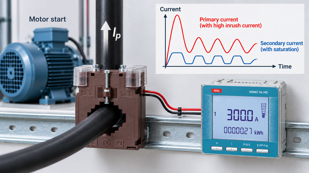
An electric motor draws a current of approximately 80 A during normal operation. A current transformer with a transformation ratio of 100/5 A is used for monitoring. During steady-state operation, the current clamp, energy meter and current transformer indication agree very well. When the motor is switched on, however, the current clamp briefly shows more than 500 A, while the measuring instrument connected via the current transformer calculates only 280 or 300 A.
At first glance, it seems likely that the measuring instrument is too slow or that the transformation ratio has been parameterised incorrectly. Both are possible. However, with very high inrush currents, there is another potential cause: the magnetic core of the current transformer can saturate.
As long as the transformer is operated within its intended working range, the secondary current follows the primary current approximately according to the transformation ratio. With a 100/5 A transformer, for example, 100 A on the primary side corresponds to 5 A on the secondary side. A primary current of 80 A ideally results in approximately 4 A secondary current.
A motor start with 500 A would, mathematically, require 25 A secondary current. Whether the transformer can actually transmit such a current proportionally does not depend solely on the printed ratio of 100/5 A. Core material, core cross-section, winding, burden, frequency, DC components in the current waveform and the specific transformer class determine how far into the overcurrent range the current transformer continues to operate proportionally.
If the core saturates, the magnetic flux no longer increases accordingly. The secondary current then no longer reproduces the primary current proportionally. In particular, the peaks of the current waveform become distorted or clipped. As a result, the connected measuring instrument can indicate a significantly lower inrush current than is actually flowing through the primary conductor.
The most important rule is therefore: The transformation ratio alone does not describe the behaviour of a current transformer at very high currents. For inrush, starting and fault currents, the saturation behaviour, transformer class, instrument security factor or accuracy limit factor, and the actual secondary burden must also be taken into account.
How does a conventional current transformer work?
In simplified terms, a conventional AC current transformer consists of a magnetic core through which the primary conductor passes and a secondary winding. The primary conductor often forms just a single turn. The current flowing through the primary conductor generates a magnetic flux in the core. This flux induces a voltage in the secondary winding and thereby drives the secondary current through the connected secondary circuit.
The ratio of the number of turns essentially determines the transformation ratio. With a 400/5 A current transformer, a primary current of 400 A should produce a secondary current of 5 A under rated conditions. At 200 A primary current, the ideal secondary current is 2.5 A.
However, a current transformer is not an ideal mathematical converter. Part of the primary current is required to magnetise the core. Winding resistance, the magnetic properties of the core material, frequency and the connected secondary burden therefore determine the actual transformation accuracy.
Within the normal measuring range, these errors are small with a correctly selected transformer and are limited by the accuracy class. In the overcurrent range, the situation changes. The further the primary current rises above the rated current, the closer the core approaches its magnetic limit.
Why are inrush currents particularly critical?
Many electrical loads draw considerably more current for a short period when switched on than during subsequent steady-state operation. A typical example is the direct-on-line starting of an asynchronous motor. Depending on the motor, supply network and mechanical load, the starting current can reach several times the rated current.
Transformers can also produce very high current peaks when switched on. The waveform is often strongly asymmetrical and depends on the point on the voltage waveform at which switching occurs as well as on the residual magnetisation of the transformer core.
This creates a completely different task for the current transformer than during normal operation. A transformer selected for an operating current of 80 to 100 A can be subjected to several hundred amperes for a short period.
Whether this peak must be transmitted completely depends on the actual measurement task. For a simple operating-current indication, it may be perfectly adequate or even intentional for the measuring current transformer to cease operating proportionally in the high overcurrent range. If, on the other hand, the actual motor start is to be analysed, a protection function is to be supplied or an event recorder is to be fed, this saturation may be undesirable.
Before selecting a transformer, it must therefore first be determined which current range is actually relevant to the measurement task.
What does magnetic saturation mean?
The magnetic flux in the core does not increase proportionally with magnetising force without limit. As the magnetic field strength increases, the core material approaches a region in which additional magnetisation produces only a comparatively small increase in magnetic flux density.
This region is referred to as magnetic saturation.
For a current transformer, this means that the core can no longer maintain the magnetic condition required for proportional secondary-current transmission. An increasing proportion of the primary current is then effectively required for magnetising the core rather than being correspondingly transferred to the secondary side.
The secondary current therefore no longer increases in the same proportion as the primary current.
Saturation is not a hard switch that suddenly changes from “correct” to “incorrect”. The behaviour becomes progressively nonlinear. The error initially increases and the current waveform can subsequently become significantly distorted.
With a sinusoidal primary current, the regions of high instantaneous current amplitude are particularly affected. The secondary waveform loses its original shape and the peaks become flattened.
How saturation distorts the indicated current
A digital measuring instrument does not receive the primary current itself, but only the secondary signal of the current transformer. If this signal is distorted by saturation, even a perfectly functioning measuring instrument can no longer reconstruct the original primary current from it.
Assume that a 100/5 A transformer is subjected to 500 A primary current during a motor start. Without saturation, an ideal secondary current of 25 A would be expected.
If the core saturates significantly earlier, only much smaller and heavily distorted secondary-current peaks may occur. An RMS measuring instrument will calculate a correspondingly lower RMS value from this signal.
An indication of, for example, 300 A then does not mean that the motor actually drew only 300 A. It merely means that the secondary signal supplied by the current transformer corresponds to a lower calculated primary value.
For short events, the dynamic response of the measuring instrument is an additional factor. A panel meter with a slow update rate can also average the starting current over time. Saturation and instrument filtering can therefore overlap.
For diagnostic purposes, the current transformer and the evaluation instrument must therefore be assessed separately.
Why the transformation ratio alone is not sufficient
The designation 100/5 A initially describes the rated operating point of the transformer. It does not automatically mean that any arbitrary primary current up to, for example, 1000 A will be transmitted with exactly the same ratio.
In addition to the transformation ratio, the transformer characteristics relevant to selection include at least the accuracy class, rated burden and the parameters describing behaviour in the overcurrent range.
A 100/5 A measuring current transformer with accuracy class 0.5 and a low instrument security factor can behave very differently during a high motor starting current from a protection current transformer that also has a 100/5 A ratio but a protection class of 5P20.
Both have nominally the same transformation ratio. Their purpose and their behaviour outside the normal rated range are fundamentally different.
Therefore, when investigating an unusual inrush-current measurement, the question should not only be: “Is 100/5 A configured correctly?” Just as important is: “Which transformer class is actually installed, and for what overcurrent range is it intended?”
What role does the burden play in saturation?
The secondary burden determines the voltage that the current transformer must generate in order to drive the required secondary current through the connected circuit.
For a predominantly resistive burden, the following simplified relationship applies:
US ≈ IS × Zburden
The greater the burden, the higher the secondary voltage that the current transformer must generate. A higher required secondary voltage also means greater magnetic stress on the core.
A high burden can therefore cause a current transformer to saturate at a lower primary current than it would with a smaller secondary burden.
The actual burden includes the current-measuring input, the outgoing and return conductors, test terminals, contact resistances and any other devices connected in series. Particularly in 5 A secondary circuits, longer cables can contribute a considerable VA burden.
This means that a current transformer may still reproduce a high current relatively well during commissioning when a test instrument is connected directly beside it, but saturate significantly earlier after connection to a long secondary cable.
| Influencing factor | Effect | Significance at high currents |
|---|---|---|
| Higher secondary burden | Transformer must generate a higher secondary voltage | Saturation may occur earlier |
| Longer secondary cable | Cable resistance increases | Additional burden |
| Smaller conductor cross-section | Cable resistance increases | Additional burden and voltage requirement |
| Several devices connected in series | Individual burdens are added together | Less reserve in the overcurrent range |
| 1 A secondary circuit | Significantly lower cable burden at the same cable resistance | Advantageous for longer distances |
The burden is therefore not merely an accuracy issue for the normal measuring range. It also influences how the current transformer behaves at high currents.
Measuring current transformers and intentional saturation
With a measuring current transformer, saturation in the overcurrent range is not necessarily a design fault.
On the contrary, a conventional measuring core should operate as accurately as possible within the normal operating range, but should protect connected measuring and metering equipment against excessive secondary-current loading at very high overcurrents.
For suitable measuring current transformers, an instrument security factor is specified for this purpose. The transformer is therefore deliberately optimised differently from a protection current transformer.
This behaviour is useful for normal energy or operating-current measurement. A high short-circuit current does not have to be transmitted with full accuracy to a connected panel meter.
Problems arise only when the same measuring transformer is suddenly used for a different task – for example, detailed recording of motor starting current or assessment of very high short-duration currents.
In such cases, the intended protective behaviour of the measuring core can become a metrological limitation.
Why protection current transformers are designed differently
In the event of a fault, a protection relay requires information about high currents that is as reliable as possible. A protection current transformer must therefore be capable of transmitting much further into the overcurrent range before saturation becomes excessive.
Its primary task is not to achieve the smallest possible measurement error at, for example, 30 or 50 percent of rated current for energy billing. What matters is that a high short-circuit or fault current is transferred to the protection device with sufficient accuracy.
Protection current transformers are therefore specified using different classes and limit factors.
However, this does not automatically make a protection current transformer the better measuring transformer for every application. Different error limits can apply to precise operating-current or energy measurement. The respective core characteristics must match the task.
In larger installations, separate measuring and protection cores may therefore be used: one core for precise measurement within the normal operating range and a second core for the protection function in the overcurrent range.
Correctly understanding the instrument security factor FS
For measuring current transformers, the instrument security factor FS describes the intended behaviour in the overcurrent range. Typical designations include FS5 and FS10.
In simplified terms, a lower FS value means that the measuring core is intended to enter the saturation region comparatively earlier and thereby limit high secondary currents more effectively for the connected measuring instruments.
However, it is important not to consider the FS value independently of the burden. The specified transformer characteristic refers to defined operating conditions and, in particular, to the specified burden.
A significantly lower actual burden can cause the transformer to enter strong saturation only at a higher primary current. A higher burden, by contrast, can promote earlier saturation.
A nameplate designation such as “Class 0.5 FS5 5 VA” therefore represents a related set of specifications. The individual values should not be interpreted in isolation.
For simple operating-current measurement, an appropriate FS value is advantageous. Anyone wishing to record the actual six- or eight-times motor starting current as accurately as possible must, however, check whether this overcurrent range is intended to be reproduced by the selected measuring core at all.
Understanding 5P10, 5P20 and the accuracy limit factor
For protection current transformers, designations such as 5P10 or 5P20 are found instead of the instrument security factor.
In simplified terms, the number following the P describes the accuracy limit factor for the specified rated burden. A 5P20 protection current transformer is intended for a different task from a conventional Class 0.5 measuring transformer.
The protection core is intended to provide a sufficiently usable secondary signal for the protection function even at a high multiple of the rated current.
Here too, the actual burden influences the real behaviour. A protection current transformer should therefore not be selected solely from the marking 5P20. Rated burden, secondary current, cable resistance and the requirements of the connected protection relay must be considered together.
For more complex protection tasks, additional characteristics such as knee-point voltage, winding resistance and transient behaviour can also become relevant. These values are often unnecessary for a conventional control-cabinet measurement task, but they can be decisive for protection and event recording.
1 A or 5 A for dynamic applications
The rated secondary current has a significant influence on the cable burden in particular.
For a resistive cable:
S = I² × R
At the same cable resistance, a 5 A secondary circuit therefore produces 25 times the cable burden of a 1 A secondary circuit.
With short connections inside a control cabinet, this difference may be small enough to have virtually no practical effect. With longer cables between the current transformer and the measuring or protection device, however, it can become significant.
The lower secondary cable burden of a 1 A system reduces the voltage that the transformer must generate. This can be advantageous particularly with high overcurrents and long cable runs.
Changing from 5 A to 1 A is not, however, a software setting that can simply be changed on the current transformer afterwards. The transformer and connected device must both be designed for the same rated secondary current or parameterised accordingly.
Consider asymmetrical inrush currents and DC components
Another reason why inrush currents are more difficult for current transformers than an equally large steady-state sinusoidal AC current is the possible asymmetry of the current waveform.
When a motor or transformer is switched on, the current can contain a pronounced transient DC component. The positive and negative half-waves are then initially not symmetrical.
This is unfavourable for the magnetic core because the magnetic flux does not return completely symmetrically during the individual half-waves. As a result, the core can very quickly enter the saturation region in one direction.
In addition, the current transformer may retain residual magnetisation. If the core has retained remanent flux from a previous event and this points in an unfavourable direction, the next current peak can cause saturation even earlier.
Two switching events with nominally the same RMS current therefore do not necessarily produce exactly the same secondary waveform.
For protection technology and highly dynamic event recording in particular, the time-domain shape of the current is therefore just as relevant as its magnitude.
Assess the current transformer and measuring instrument separately
When the indicated inrush current is too low, either the transformer or the measuring instrument is often immediately blamed. In reality, both components can limit the result.
The current transformer must first produce a sufficiently accurate secondary signal. The measuring instrument must then acquire and process this signal quickly enough.
A panel meter that updates its display only a few times per second, for example, may fail to display a very short peak completely even if the current transformer has transmitted it correctly.
Conversely, even a high-resolution, fast recorder cannot reconstruct a primary-current peak that has already been lost in a saturated current transformer.
An independent comparison measurement is therefore useful for troubleshooting. A suitable fast current clamp, Rogowski system or another measuring method specified for the expected dynamics can show whether the deviation already occurs in the transformer secondary signal or only in the subsequent evaluation.
Practical example: motor with six-times rated starting current
A motor has a rated current of 90 A. A 100/5 A current transformer has been installed for operating-current indication. During normal operation, the connected measuring instrument shows 89 to 91 A. The measurement is therefore fundamentally plausible.
During direct-on-line starting, an appropriate independent measurement shows a short-term primary current of approximately 540 A. This corresponds to six times the rated current of the motor.
However, the panel meter connected via the current transformer shows a maximum of only around 330 A during startup.
The parameterisation is checked first. The 100/5 A ratio is correctly configured in the measuring instrument. The phase assignment is also correct.
The secondary side is then examined. Approximately 15 m of cable is installed between the current transformer and measuring instrument. In addition, there is a test disconnect terminal in the secondary circuit. The actual burden is therefore higher than originally assumed.
The combination of very high primary inrush current and secondary burden causes the measuring core to saturate during part of the startup process. The secondary-current waveform is flattened and no longer reproduces the primary peak proportionally.
The installed current transformer remains suitable for its normal operating purpose. However, the task has changed: the actual motor starting current is now also to be documented.
The transformation ratio in the measuring instrument is not simply changed for this purpose. Instead, it is checked which current transformer or alternative measuring method provides the required dynamic range and bandwidth.
The example shows why the statement “the current transformer measures correctly during operation” does not prove that it will also correctly capture a transient current peak six times higher.
Systematically diagnose saturation
A characteristic indication of current-transformer saturation is a measuring chain that agrees very well within the normal operating range but increasingly indicates values that are too low at high currents.
A comparison with an independent measuring method is particularly informative. If the actual primary current continues to increase while the current calculated from the current-transformer secondary signal increases only slightly, this indicates nonlinearity in the transformer or secondary circuit.
| Observation | Possible cause | Sensible check |
|---|---|---|
| Normal current correct, inrush current significantly too low | Current-transformer saturation or excessively slow evaluation | Compare secondary signal with an independent primary-current measurement |
| Deviation increases with higher burden | Secondary circuit requires too much voltage | Calculate burden and cable resistance |
| All current values are proportionally incorrect | Incorrect transformation ratio or parameterisation | Check transformer data and measuring-instrument parameters |
| Only very short peaks are missing | Measuring-instrument bandwidth or update rate | Use a faster recorder or suitable comparison measurement |
| Strongly distorted secondary waveform at a high primary peak | Magnetic saturation | Check transformer class, burden and overcurrent requirement |
| Different behaviour during apparently identical starts | Transient DC component or remanence possible | Analyse the time-domain waveform rather than only the RMS maximum |
A diagnosis based solely on a single maximum display value is difficult. For dynamic processes, the time-domain waveform is much more informative.
Selecting current transformers for high inrush currents
Transformer selection should not begin by choosing the largest possible primary rated current. The measurement task must first be defined.
If only the normal operating current of a motor is to be monitored, the current transformer should be sized so that the relevant operating range is used effectively. Selecting an extremely large primary range solely because of a short starting current can unnecessarily reduce the resolution or accuracy within the normal operating range.
If, on the other hand, the inrush current itself is to be quantitatively evaluated, the expected maximum current amplitude, duration and waveform must be known, together with the required accuracy.
The transformer type, transformation ratio, secondary current, accuracy or protection class and actual burden are then considered together. For longer secondary cables, a 1 A system can offer advantages. For protection functions, the overcurrent transmission required by the relay must additionally be taken into account.
The mechanical installation must not be forgotten either. The current-transformer opening must fit the conductor or busbar, and the thermal and dynamic primary-current limits of the transformer must be observed.
The optimum solution can therefore be different for operating-current measurement, energy metering, motor-start analysis and protection applications.
Never open the secondary circuit improperly
From a safety perspective, a conventional current transformer differs significantly from a normal voltage transformer.
While primary current is flowing, the current transformer attempts to generate a corresponding secondary current. If the secondary circuit is opened, this current can no longer flow.
As a result, dangerously high voltages can develop across the open secondary circuit. At the same time, the core is strongly magnetised and the transformer may be subjected to thermal or magnetic stress.
A current-transformer secondary circuit must therefore not simply be opened while primary current is flowing, for example to quickly replace a measuring instrument or insert a multimeter.
Suitable test or short-circuit terminals are used for such work. The secondary winding is first safely short-circuited before the connected measuring instrument is disconnected.
This point is also important during troubleshooting. A poorly contacting test disconnect terminal can increase the actual burden or, in the worst case, briefly create an unwanted open secondary circuit.
Common planning and interpretation errors
Considering only the transformation ratio
The designation 200/5 A does not state up to which overcurrent the transformer will continue to reproduce the primary current proportionally. Accuracy class, burden and overcurrent characteristics must also be considered.
Treating inrush current as part of the normal operating range
A short-term motor current six or eight times the rated value produces a different magnetic loading than a continuous sinusoidal rated current.
Equating measuring and protection current transformers
A measuring core should operate accurately within the normal range and may intentionally saturate during high overcurrents. A protection core, by contrast, must continue to transfer high fault currents much further into the overcurrent range.
Assuming that a high VA rating is automatically better
The transformer burden must match the actual secondary load. Transformer class, burden and required overcurrent behaviour must be considered together.
Ignoring the secondary cable when considering saturation
Cable resistance increases the burden. This contribution can be considerable, especially with 5 A systems and longer cable runs.
Interpreting every low starting-current indication as saturation
A slow measuring instrument, unsuitable RMS evaluation or insufficient sampling rate can also underestimate short peaks. The measuring chain must be analysed separately.
Simply increasing the primary range substantially
A 600 A current transformer does not automatically solve every problem for a 100 A motor. An oversized measuring range can reduce the quality of normal operating-current measurement.
Opening the secondary circuit under load
This is safety-critical. Current-transformer secondary circuits must be handled using the intended short-circuiting and test devices.
Suitable current transformers at ICS Schneider
ICS Schneider Messtechnik offers measuring, precision, protection, split-core and three-phase current transformers for low-voltage installations, control-panel construction, energy monitoring and protection applications.
The current and voltage transformers category includes different designs and current ranges for cables and busbars. Selection should therefore be based not only on the primary rated current but also on the intended measurement or protection function.
For conventional measurement tasks, window-type current transformers for measurement are available with different transformation ratios, accuracy classes and VA ratings.
For higher measurement-accuracy requirements, precision current transformers can be used. Depending on the series, different classes, secondary currents and instrument security factors are available.
The TA 327, for example, is a single-phase precision current transformer for cables or busbars. Different burden ratings are available depending on the version. For a specific application, the selected version must match the transformation ratio, connected secondary burden and required measurement accuracy.
For protection applications, dedicated protection current transformers are available. Their behaviour at high currents intentionally differs from that of conventional measuring current transformers.
The TAU 81P, for example, is available with rated secondary currents of 1 A or 5 A and different protection classes up to 5P20. The suitable version depends on primary current, burden, protection device and required overcurrent behaviour.
For enquiries involving applications with high inrush currents, the normal operating current, maximum expected inrush or fault current, duration of the current peak, required secondary current, cable length, conductor cross-section, connected instrument burden and the actual function – measurement or protection – should therefore be specified wherever possible.
Current and voltage transformers at ICS Schneider
Further reading: Correctly sizing current-transformer burden
Further reading: Correctly connecting and checking current transformers on an energy meter
Conclusion
A current transformer that measures normal operating current correctly does not automatically transmit a high inrush current with the same accuracy.
The transformation ratio describes rated operation – behaviour at high overcurrents is additionally determined by the core characteristics, transformer class, burden and time-domain current waveform.
If the core saturates, the secondary current no longer increases proportionally with the primary current. The current waveform becomes distorted and the downstream indication can significantly underestimate the actual inrush current.
With measuring current transformers, this behaviour is partly intentional in the high overcurrent range. A limited instrument security factor protects the connected measuring instruments. For protection technology or accurate analysis of high inrush currents, however, transformers or measuring methods are required that can transmit a larger dynamic range.
The burden plays a central role. The greater the secondary impedance, the more voltage the current transformer must generate. Long cables, small conductor cross-sections and additional measuring instruments can therefore influence the onset of saturation.
For reliable design, the operating current, expected inrush or fault current, transformer class, secondary current, actual burden and the dynamics of the connected measuring instrument should therefore be considered together.
By separating these quantities correctly, apparently contradictory measurements can be explained: a current transformer can operate with high accuracy at 80 A and still indicate significantly too little during a 500 A motor start – without either its transformation ratio or the connected measuring instrument necessarily being fundamentally incorrect.
FAQ on current transformers with high inrush currents
Why does my current transformer indicate too little current during motor startup?
One possible cause is magnetic saturation of the transformer core. At high primary currents, the secondary signal may no longer increase proportionally. In addition, a slow measuring instrument can underestimate short current peaks.
Is a 100/5 A current transformer automatically capable of providing 25 A secondary current at 500 A primary current?
No. The 25 A result follows only from the ideal transformation ratio. Whether this current is actually transmitted depends, among other factors, on the core, transformer class, burden and overcurrent behaviour.
What does saturation mean in a current transformer?
The magnetic core enters a nonlinear region in which additional primary current is no longer converted proportionally into higher secondary current. This causes both magnitude and waveform errors.
Can the burden influence when a current transformer saturates?
Yes. A higher secondary burden requires a higher secondary voltage. This increases the magnetic stress on the core, and saturation may therefore occur at a lower primary current.
Is the secondary cable part of the burden?
Yes. The resistance of the complete outgoing and return cable is part of the burden, just like the measuring input and any other components in the secondary circuit.
Why is 1 A often advantageous for long cable runs?
The cable burden is proportional to the square of the secondary current. At the same cable resistance, a 5 A circuit therefore produces 25 times the cable burden of a 1 A circuit.
What is the difference between a measuring and a protection current transformer?
A measuring current transformer is optimised for high accuracy within the normal operating range and is often intended to saturate earlier during severe overcurrents. A protection current transformer is designed to continue transmitting high fault currents with sufficient accuracy to a protection relay.
What does FS5 mean for a measuring current transformer?
FS denotes the instrument security factor. It characterises the intended overcurrent and saturation behaviour of the measuring core under defined conditions. A lower FS value generally means stronger limitation of the transmitted overcurrent.
What does 5P20 mean for a protection current transformer?
The designation describes a protection class with an accuracy limit factor. The transformer is designed to operate within the error limits specified for this protection class even at a high multiple of rated current, provided the specified conditions including burden are met.
Is a 5P20 protection current transformer automatically better than a Class 0.5 measuring transformer?
No. The two are optimised for different tasks. A measuring current transformer may be more suitable for precise operating-current or energy measurement, while the protection current transformer is designed for high fault currents.
Can a current transformer saturate during motor startup even if the average current is not particularly high?
Yes. The time-domain current waveform is decisive. High peaks and a transient DC component can stress the core much more strongly than a steady-state sinusoidal current with the same RMS value.
What does remanence mean in a current transformer?
After a strong magnetic event, residual flux can remain in the core. During a subsequent current event, this residual magnetisation can influence the point at which the core enters saturation again.
Can a digital panel meter additionally underestimate the inrush current?
Yes. Update rate, RMS calculation, averaging and digital filters determine how short current events are displayed. Transformer and evaluation electronics must therefore be checked separately.
How can I determine whether the current transformer or the measuring instrument is causing the limitation?
It is useful to compare the primary current with an independent, sufficiently fast measuring method and – where safe and technically appropriate – record the secondary-current waveform. If the secondary signal is already distorted, the limitation occurs before the downstream evaluation.
Should I simply use a 600 A current transformer for a motor with a 100 A operating current so that the starting current fits?
Not automatically. The normal operating range would then use only a small portion of the transformer’s range. It must first be clarified whether the starting current actually needs to be measured accurately using the same measuring chain.
Can I use a conventional measuring current transformer for a protection relay?
Only if its characteristics explicitly meet the requirements of the protection system. A conventional measuring core may intentionally saturate in the fault-current range and therefore supply the protection relay with a secondary signal that is too low.
May the secondary side of a current transformer be operated open-circuit?
A conventional current-transformer secondary circuit must not be improperly opened while primary current is flowing. Dangerous secondary voltages and severe magnetic stress can occur. Suitable short-circuiting and test terminal arrangements must be used for work on the secondary circuit.
What information do I need to select a current transformer for high inrush currents?
The required information includes the normal operating current, maximum expected inrush or fault current, duration and waveform of the current event, measurement or protection task, desired transformation ratio, 1 A or 5 A secondary circuit, secondary cable, connected burden and required accuracy or protection class.
Which ICS category is the correct one for this topic?
For conventional measuring and protection current transformers, the Current and voltage transformers (low voltage) category is the appropriate product group. The power supply / isolation transformer / DC-DC converter category, by contrast, covers power-supply and transformer solutions and is not the correct category for this article.