


A resistance thermometer can be electrically completely correct and still respond significantly more slowly than expected. The Pt100 has the correct characteristic curve, the transmitter is parameterized correctly and the connection cable does not cause any obvious error – yet the indicated temperature visibly lags behind a process temperature change.
A frequently overlooked cause lies inside the thermometer: The replaceable measuring insert is not seated correctly in the thermowell.
In industrial electrical thermometers, the actual sensing element is often located in the tip of a mineral-insulated measuring insert. This insert is pushed into a thermowell from above. The thermowell separates the sensor from the process medium and protects it against pressure, flow, corrosion and mechanical stress, for example.
Thermally, however, this creates an additional heat-transfer path. The temperature of the medium must first be transferred to the thermowell, then through its wall and finally from the thermowell to the measuring insert. Only then does the heat reach the actual sensing element.
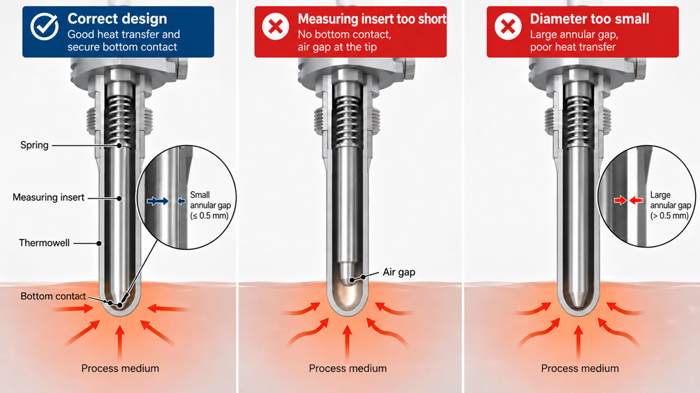
For good heat transfer, the measuring insert must therefore be geometrically matched to the thermowell. In many industrial resistance thermometers and thermocouples, the insert is spring-loaded. The spring ensures that the measuring insert tip is reliably pressed against the bottom of the thermowell despite manufacturing and installation tolerances.
However, the spring cannot compensate for every dimensional mismatch. If the measuring insert is too short, it will not reach the bottom even with the spring. If it is too long, the available spring travel can be exceeded or the installation can be mechanically overstressed. If its outside diameter is significantly smaller than the thermowell bore, a large annular gap is also created, reducing radial heat transfer.
For optimum heat transfer, WIKA therefore explicitly specifies two requirements: the correct measuring insert length and the correct measuring insert diameter. For the current TR10-B, the thermowell bore diameter should be no more than 1 mm larger than the measuring insert diameter. According to the manufacturer, gap widths greater than 0.5 mm have a negative effect on heat transfer and response behavior.
The key point is: A spring-loaded measuring insert only functions as intended if its length, diameter and spring travel match the actual thermowell geometry. Bottom contact improves axial thermal coupling, while a suitable diameter reduces the thermally unfavorable annular gap – both factors must be considered together.
Table of Contents
- How is a temperature measuring point with a thermowell constructed?
- What path does the heat take to the sensing element?
- What is the function of the spring on the measuring insert?
- Why is bottom contact so important?
- Why is the measuring insert diameter just as important?
- How an excessively large annular gap affects the measurement
- What happens if the measuring insert is too short?
- What happens if the measuring insert is too long?
- Correctly assessing spring travel and preload
- Selecting the correct measuring insert for replacement
- Pt100 and thermocouple: does the same principle apply to both?
- Why a correctly seated measuring insert cannot compensate for a poorly designed thermowell
- Distinguishing thermal from electrical measurement errors
- Why poor contact becomes particularly noticeable during temperature changes
- Thermal paste or oil in the thermowell?
- What calibration can reveal about installation errors
- Systematically diagnosing typical fault patterns
- Practical installation procedure
- Suitable temperature measurement technology from ICS Schneider
- Conclusion
- Frequently asked questions about spring-loaded measuring inserts
1. How is a temperature measuring point with a thermowell constructed?
A conventional industrial temperature measuring point consists of more than just a Pt100 or thermocouple. Several mechanical components are located between the process and the electrical output signal.
The thermowell initially forms the mechanical boundary to the process. It may, for example, be screwed in, welded in or connected to the pipe or vessel by means of a flange. As a result, the medium does not come into direct contact with the replaceable measuring insert.
Inside the thermowell is a bore or, in the case of fabricated thermowells, an internal cavity. The measuring insert is inserted into this space. In modern industrial designs, it often consists of a mineral-insulated sheathed cable. The actual Pt100, Pt1000 or thermocouple sensing element is located as close as possible to the tip.
Connection terminals or a temperature transmitter are located at the upper end of the measuring insert. In many designs, the measuring insert is mechanically mounted using a spring-loaded arrangement.
This allows the thermowell to remain permanently in the process while the actual measuring insert can be removed for inspection, calibration or replacement. Particularly in pressurized or aggressive processes, this design provides a major service advantage.
2. What path does the heat take to the sensing element?
To understand installation errors, it is useful to consider the temperature measuring point as a heat-transfer chain.
The temperature of the medium first reaches the outer surface of the thermowell. How quickly this initial heat transfer occurs depends, among other things, on the medium, its flow velocity, the insertion depth and the shape, material and surface of the thermowell.
The heat is then conducted through the thermowell material to the internal bore. From there, it must be transferred to the measuring insert. This is exactly where bottom contact and the annular gap become decisive.
Finally, the heat is transferred through the measuring insert to the actual sensing element. Only its temperature is evaluated electrically.
| Part of the measurement chain | Important influencing factors | Possible consequence of unfavorable design |
|---|---|---|
| Medium → thermowell | Flow, insertion depth, thermowell geometry | Ambient influence, slow response |
| Thermowell wall | Material, wall thickness, tip design | Additional thermal inertia |
| Thermowell → measuring insert | Bottom contact, diameter, annular gap | Poor heat transfer |
| Measuring insert → sensing element | Sensor construction and position | Additional measurement delay |
| Sensor → measurement signal | Sensor type, wiring, transmitter, filtering | Electrical measurement deviation or signal delay |
A high-quality Pt100 therefore does not automatically eliminate thermal errors caused by an unfavorable measuring-point design. The accuracy class of the sensing element initially describes the sensing element itself – not the complete temperature transfer from the process to the sensor.
3. What is the function of the spring on the measuring insert?
A replaceable measuring insert cannot be manufactured and installed so that its length precisely matches the internal thermowell geometry to within a few hundredths of a millimeter under all conditions.
Manufacturing tolerances, different connection heads, seals, fittings and temperature-related changes in length must be accommodated by the design.
The spring provides a defined axial tolerance range for this purpose.
During assembly, the measuring insert is guided down to the bottom of the thermowell. The spring is then slightly compressed when the measuring insert is secured. The resulting spring force keeps the tip pressed against the thermowell bottom.
For WIKA measuring inserts, this function is explicitly described as pressing the insert against the thermowell bottom.
The spring is therefore not intended to compensate for a major length error. Its purpose is to maintain secure contact within the intended spring travel despite small mechanical and thermal tolerances.
4. Why is bottom contact so important?
The thermowell bottom is located particularly close to the sensing element by design. At the same time, when correctly designed, the thermowell tip is located in a well-flowing or representative area of the process.
If the tip of the measuring insert rests directly against the thermowell bottom with light spring pressure, good metallic or otherwise well-defined thermal coupling is created at this point.
If this contact is missing, a gas-filled space remains between the measuring insert tip and the thermowell bottom. Air and other gases have significantly lower thermal conductivity than metallic contact.
The sensor temperature then follows the thermowell-bottom temperature more slowly. At the same time, heat conduction through the lateral sections of the measuring insert becomes relatively more important.
This becomes particularly evident during a temperature step. The thermowell is already heating up or cooling down while the sensing element responds more slowly because of the additional thermal resistance.
In a process that remains completely stable for a long period, the indication may nevertheless eventually reach a plausible value. This is precisely why missing bottom contact often remains undetected during a purely static plausibility check.
5. Why is the measuring insert diameter just as important?
A common misconception is that if the spring presses the tip against the bottom, heat transfer is automatically optimal.
This is not the case.
The measuring insert is located inside the thermowell bore over a significant portion of its length. An annular gap exists between its outer surface and the inner surface of the thermowell. Heat is also transferred across this area.
If the measuring insert is significantly thinner than the bore, the gas-filled gap becomes larger. This increases the thermal resistance between the thermowell and the measuring insert.
For this reason, WIKA explicitly specifies not only the correct length but also the correct measuring insert diameter as a prerequisite for adequate heat transfer.
For the current TR10-B, the manufacturer specifies that the thermowell bore diameter should be no more than 1 mm larger than the measuring insert diameter. Gap widths greater than 0.5 mm are described as detrimental to heat transfer and response behavior.
These values are very useful for assessing typical WIKA configurations, but they should not be applied without verification as universal limits to other manufacturers or special designs.
6. How an excessively large annular gap affects the measurement
A larger annular gap primarily results in poorer thermal coupling.
The typical consequence is not an arbitrary electrical offset, but altered dynamic behavior. The sensor requires more time to follow the temperature of the thermowell.
In a steady process, this difference may remain comparatively inconspicuous. During changing temperatures, however, significant temporary differences can occur between the actual medium temperature, the thermowell temperature and the sensor temperature.
In addition, heat-transfer paths through the upper part of the measuring insert, the neck tube or the connection head can become more significant. If the ambient temperature differs considerably from the process temperature, this can also contribute to steady-state measurement deviations.
An undersized measuring insert diameter is therefore more than just a mechanical fit issue.
When replacing a measuring insert, its length and diameter should always be checked together with the actual thermowell bore.
7. What happens if the measuring insert is too short?
If the measuring insert is significantly too short, the spring cannot perform its intended function.
The measuring insert may still be secured in the connection head, but its tip does not reach the thermowell bottom. An axial air gap remains between the two.
This error is often not visible externally. The connection head, terminals and transmitter may all appear to be mounted correctly.
A noticeably sluggish temperature response is typical. Particularly during rapid process changes, the sensor follows more slowly than expected.
With large temperature differences between the process and the environment, the influence of heat conduction along the measuring insert can also become more significant.
A measuring insert that is too short should therefore not be “corrected” by improvising spacers or modifying fastening components. The correct solution is a measuring insert with the appropriate design length.
8. What happens if the measuring insert is too long?
A measuring insert that is too long is not automatically harmless either.
A certain amount of excess length is required by design so that the spring is preloaded during assembly. However, this excess length must remain within the intended spring travel.
If the measuring insert is significantly too long, the spring is compressed excessively during fastening or reaches its mechanical limit. The connection head or fastening arrangement may then only be assembled with unusually high force.
In unfavorable cases, this can create mechanical stress on the measuring insert, connection plate or thermowell bottom.
Increasing spring force does not improve heat transfer indefinitely. Once reliable contact has been established, the main purpose of the spring is to maintain that contact securely.
For this reason, neither “as short as possible” nor “maximum possible preload” should be used as installation principles.
9. Correctly assessing spring travel and preload
The available spring travel depends on the specific design.
For various WIKA thermometers in the TR10/TC10 family, for example, a maximum spring travel of 10 mm is specified. Other device families may use different values.
The maximum available spring travel should also not be confused with the required preload.
During installation, it is only necessary to ensure that the tip reaches the bottom and that sufficient preload is established within the permissible spring travel when the insert is secured.
In its general instructions for electrical thermometers, WIKA essentially states that the spring-loaded sensor should make contact with the thermowell bottom and yield slightly during installation.
The actual measuring insert length should therefore be determined from the device drawing, thermowell geometry and manufacturer’s specification. A universal additional length in millimeters for every thermometer would not be technically appropriate.
10. Selecting the correct measuring insert for replacement
The advantage of a thermowell with a replaceable measuring insert becomes particularly clear during servicing. If the sensor is defective, the process connection can remain installed in the equipment while only the internal measuring insert is replaced.
However, this is also where fitting errors frequently occur.
The designation “Pt100, 6 mm” is not sufficient for a reliable replacement. At minimum, measuring insert length, diameter, connection arrangement, sensor type, wiring configuration and, where applicable, hazardous-area version must also be considered.
The original order or device documentation is the most reliable source of information.
The old measuring insert can also be used for comparison, but it should not be the only source of information. If an incorrectly dimensioned measuring insert was itself the cause of the problem, its dimensions would otherwise simply be copied again.
| Check when replacing | Why? |
|---|---|
| Measuring insert length | Determines bottom contact and spring preload |
| Measuring insert diameter | Determines annular gap and heat transfer |
| Sensor type | Pt100, Pt1000 or thermocouple must match the evaluation electronics |
| Wiring configuration | For RTDs, e.g. 2-, 3- or 4-wire connection |
| Temperature range | Sheathed cable, sensor and connection design each have their own limits |
| Hazardous-area version | Approved combination and replacement-part requirements must be maintained |
| Transmitter | Measuring range, sensor type and parameterization must match the measuring point |
Particular care is required for hazardous-area versions. Mechanical fits and approval conditions may prevent an externally compatible standard measuring insert from being used as a replacement.
11. Pt100 and thermocouple: does the same principle apply to both?
The basic principle applies both to resistance thermometers and to thermocouples with replaceable measuring inserts.
In a resistance thermometer, for example, a Pt100 or Pt1000 is located in or near the measuring insert tip. In a thermocouple, the thermocouple measuring junction is located in the tip area.
In both cases, the temperature of the thermowell must be transferred as efficiently as possible to the sensitive area of the measuring insert.
For this reason, WIKA offers both the TR10-A as a spring-loaded measuring insert for resistance thermometers and the TC10-A for thermocouples. For both versions, the manufacturer describes compression springs that press the insert against the thermowell bottom.
The different sensor principles do not change this fundamental mechanical and thermal requirement.
Even a particularly fast thermocouple will perform below its potential if a large, thermally sluggish thermowell and an unfavorable annular gap dominate the heat-transfer path.
12. Why a correctly seated measuring insert cannot compensate for a poorly designed thermowell
Bottom contact and a small annular gap optimize only the heat-transfer path inside the thermometer.
This does not yet ensure that the thermowell bottom itself represents the actual process temperature.
If the thermowell is inserted too shallowly into a pipe, for example, its tip can be influenced more strongly by heat conduction toward the pipe wall or surrounding environment. An unfavorable flow position or an oversized thermowell can also increase response time.
These two aspects must therefore be considered separately.
On the process side, the thermowell must be correctly designed and inserted sufficiently far into the medium. On the sensor side, the measuring insert must in turn be seated correctly inside the thermowell.
Perfect bottom contact cannot compensate for an incorrect thermowell insertion depth. Conversely, an optimally positioned thermowell provides little benefit if the sensor ends several millimeters above its bottom.
13. Distinguishing thermal from electrical measurement errors
Not every sluggish or implausible temperature reading is caused by poor heat transfer.
With resistance thermometers, lead resistance, incorrect 2-/3-/4-wire configuration, contact problems or an incorrect sensor setting in the transmitter can cause deviations.
With thermocouples, additional causes include an incorrect thermocouple type, unsuitable extension or compensating cable, reversed polarity and errors in cold-junction compensation.
Electrical errors and thermal installation errors often show different behavior.
An incorrect transmitter range can, for example, create a systematic scaling error across the entire process range. Poor thermal coupling, by contrast, often becomes especially apparent during rapid temperature changes.
For troubleshooting, it should therefore first be checked whether the sensor is being evaluated correctly electrically. The time response should then be assessed against the actual process dynamics.
14. Why poor contact becomes particularly noticeable during temperature changes
The effect of poor heat transfer can be observed particularly clearly during a temperature step.
If the process temperature rises quickly, the thermowell heats up first. With good thermal coupling, the measuring insert tip follows comparatively quickly.
If an air gap is present, heat takes longer to reach the sensor. The indicated value therefore temporarily lags behind the actual process temperature.
The same effect occurs in the opposite direction during subsequent cooling.
In a control loop, this additional time constant can be more problematic than a small constant measurement error. The control system reacts to a process state that has already progressed further than the indicated temperature suggests.
This is particularly critical in rapid heating and cooling processes, thermal test benches or small process volumes.
In very slow processes, the same mechanical error can remain unnoticed for a long time.
15. Thermal paste or oil in the thermowell?
A large air gap sometimes leads to the idea of filling the thermowell with thermal paste, oil or another medium.
In principle, a suitable heat-transfer medium can reduce the thermal resistance of a gas-filled gap. However, this does not mean that arbitrary heat-transfer compounds should be introduced into every thermowell.
Temperature resistance, aging, outgassing, chemical compatibility, possible resin formation and the later replaceability of the measuring insert must all be considered.
In high-temperature applications, for example, a product that is suitable at room temperature may be completely unsuitable. In other applications, a heat-transfer compound can bond the measuring insert so strongly that later replacement becomes difficult.
The primary solution for a standard industrial measuring point should therefore be a geometrically matched combination of thermowell and measuring insert.
Heat-transfer compounds should only be used if explicitly intended by the manufacturer or by the specific design and if they are suitable in terms of temperature and application.
16. What calibration can reveal about installation errors
A removed measuring insert can produce excellent results in a calibration bath or dry-well calibrator and still show unsatisfactory process behavior after installation.
This is not a contradiction.
When the measuring insert is calibrated, the sensing element or electrical measurement chain is primarily assessed. The actual thermal coupling to the operational thermowell is not necessarily part of the test.
If a sensor with a good calibration result is subsequently installed in a thermowell with an excessively large internal diameter or without bottom contact, the additional thermal time constant remains.
A complete assessment of the measuring point must therefore distinguish between sensor calibration and installation effects.
For particularly critical measuring points, it can be useful to evaluate not only the sensor calibration itself but also the dynamic behavior of the complete temperature measuring assembly.
17. Systematically diagnosing typical fault patterns
| Observation | Possible cause | Recommended check |
|---|---|---|
| Temperature responds significantly more slowly after replacing the measuring insert | Replacement insert too short or diameter too small | Compare length, diameter and thermowell bore with the original data |
| Connection head can only be assembled with unusually high force | Measuring insert too long or spring travel exhausted | Check insertion length and permissible spring travel |
| Sensor appears plausible under steady conditions but follows temperature steps slowly | Poor thermal contact | Check bottom contact and annular gap |
| Measured value changes after loosening and re-fastening the measuring insert | Spring contact or seating has changed | Check mechanical installation and preload |
| New measuring insert cannot be fully inserted | Diameter, sleeve or thermowell bore does not match | Check dimensions and possible contamination inside the bore |
| Calibrated sensor still shows deviations in the process | Installation, heat-transfer or thermowell influence | Evaluate the complete measuring point rather than only the sensing element |
| Indication immediately shows a constant offset | Possibly an electrical rather than thermal error | Check wiring, cable, transmitter and sensor parameterization |
| Measurement becomes noticeably sluggish during rapid flow changes | Large thermal mass or poor coupling | Check thermowell geometry, annular gap and bottom contact together |
18. Practical installation procedure
Before installing a new measuring insert, it should first be clearly established which thermowell and thermometer design it is intended for.
The relevant dimensions should ideally be taken from the original device design, data sheet or order code. Length and diameter should be checked together.
It should then be verified that the measuring insert can be inserted down to the thermowell bottom without unusual resistance. Deposits, corrosion or mechanical damage inside the thermowell can also prevent the tip from reaching its intended position.
Spring action should be noticeable during fastening. This indicates that the measuring insert has reached the bottom and that the intended preload is being generated.
An unusually large amount of compression, by contrast, is not a sign of quality but a reason to check the insertion length again.
The electrical connections or transmitter should then be checked. Only after this should the behavior of the complete measuring point be assessed during a plausible process change.
This approach allows mechanical, thermal and electrical faults to be checked one after another rather than being mixed together.
19. Suitable temperature measurement technology from ICS Schneider
ICS Schneider Messtechnik offers resistance thermometers, thermocouples, replaceable measuring inserts and thermowells for industrial temperature measuring points. An overview can be found under Temperature Measurement Technology.
WIKA TR10-B Resistance Thermometer
The WIKA TR10-B is designed for installation in common thermowell designs and features a replaceable, spring-loaded measuring insert.
Depending on the version, Pt100 or Pt1000 sensors are available together with different connection heads, insertion lengths, neck lengths and transmitter configurations.
Depending on the version, the sensor range extends from −196 … +600 °C. This makes the design suitable for numerous applications in machine building, plant engineering, vessel construction, energy technology and chemical and process plants.
WIKA TR10-A as a Replacement Measuring Insert
The WIKA TR10-A is a replaceable measuring insert for resistance thermometers.
It consists of a flexible mineral-insulated sheathed cable with the sensing element located in the tip area. Compression springs ensure that the measuring insert is pressed against the thermowell bottom in the thermometer for which it is intended.
For replacement, it is essential to specify not only the sensor type and temperature range but also the correct length and diameter for the existing thermowell geometry.
WIKA TC10-A for Thermocouples
The WIKA TC10-A provides the corresponding design principle for thermocouples.
The mineral-insulated measuring insert is also spring-loaded and designed to be pressed against the thermowell bottom. Depending on the version, the available temperature range extends up to +1,200 °C.
The basic rules concerning length, bottom contact and thermal coupling therefore apply not only to Pt100 measuring points.
WIKA Thermowells
Under Thermowells, ICS offers various fabricated and solid-machined WIKA designs for threaded, welded or flanged installation.
One example is the WIKA TW15. For a completely new measuring-point design, the thermowell and measuring insert should be considered from the outset as one combined thermal and mechanical system.
Application Engineering by ICS Schneider
For selecting a suitable measuring insert, relevant information includes the thermometer type, existing thermowell, internal bore, required measuring insert length, diameter, sensor type, temperature range, wiring configuration, transmitter, process conditions and, where applicable, hazardous-area approval.
For replacement measuring points, it is also helpful to have the order code, nameplate or original drawing of the existing temperature measuring point available.
20. Conclusion
A spring-loaded measuring insert is a simple but highly effective design solution for electrical thermometers installed in thermowells.
The spring ensures that the measuring insert tip remains in contact with the thermowell bottom despite small length and installation tolerances. This improves heat transfer in the particularly important tip area.
However, the spring alone does not guarantee good temperature measurement.
If the measuring insert is too short, an air gap remains between it and the thermowell bottom. If it is too long, the intended spring travel may be exceeded. If its diameter is too small, a thermally unfavorable annular gap is created between the measuring insert and the thermowell.
WIKA therefore explicitly requires the correct measuring insert length and a suitable measuring insert diameter. For the TR10-B, the thermowell bore should be no more than 1 mm larger than the measuring insert diameter; according to the manufacturer, gap widths greater than 0.5 mm impair heat transfer and response behavior.
This internal fit must be distinguished from the process-side design of the thermowell. Even a perfectly seated measuring insert will not provide optimum measurement if the thermowell itself is too short, poorly positioned or thermally oversized.
Likewise, a good calibration result for the removed sensor must not automatically be equated with a good complete measuring point. Calibration can confirm the electrical quality of the sensing element while an installation error inside the thermowell remains.
For servicing and replacement, a clear sequence therefore applies:
Know the thermowell geometry → determine the correct measuring insert length → select the correct diameter → establish bottom contact → check spring travel → verify the electrical configuration → assess dynamic process behavior.
Following these points not only reduces the response time of the measuring point. It also ensures that the accuracy of the actual Pt100 or thermocouple can be effectively utilized in the process.
21. Frequently asked questions about spring-loaded measuring inserts
Why is a measuring insert spring-loaded inside a thermowell?
The spring ensures that the measuring insert tip is reliably pressed against the thermowell bottom within the intended tolerance range. This improves thermal contact and accommodates length and installation tolerances.
Does the measuring insert have to touch the thermowell bottom?
For the electrical thermometers with spring-loaded measuring inserts discussed here, yes. WIKA explicitly specifies that the measuring insert should be pressed against the thermowell bottom.
Does this also apply to mechanical thermometers?
Not necessarily. WIKA explicitly distinguishes between the two: with electrical thermometers, the spring-loaded sensor should touch the thermowell bottom. With certain mechanical thermometers, however, a small clearance to the bottom is specified. The installation principles must therefore not be transferred without verification.
What happens if the measuring insert is too short?
The tip does not reach the thermowell bottom. The resulting air gap reduces thermal coupling and can significantly increase response time, particularly during temperature changes.
What happens if the measuring insert is too long?
A certain amount of excess length is required for spring preload. However, if the insert is too long, the permissible spring travel can be exceeded or the assembly can be subjected to unnecessary mechanical stress.
How much spring travel is required?
This depends on the specific thermometer design. For many WIKA TR10/TC10 versions, the maximum available spring travel is 10 mm. However, this value must not be applied universally to other designs.
Why is the measuring insert diameter important?
An undersized measuring insert creates a larger gas-filled gap between the measuring insert and the thermowell. This reduces heat transfer and causes the thermometer to respond more slowly.
How large may the difference between thermowell bore and measuring insert diameter be?
For the WIKA TR10-B, the manufacturer specifies that the bore diameter should be no more than 1 mm larger than the measuring insert diameter. Gap widths greater than 0.5 mm have a negative effect on heat transfer and response behavior. For other designs, the relevant manufacturer’s specifications apply.
Is bottom contact more important than the lateral gap?
Both factors are relevant. Bottom contact ensures good thermal coupling at the tip, while a suitable diameter improves heat transfer between the thermowell and measuring insert along the insertion length.
Can an air gap cause a temperature measurement error?
Yes. Particularly during temperature changes, poor thermal coupling causes the sensor temperature to respond with a delay. With large temperature differences relative to the environment, steady-state installation effects can also become greater.
Why does an incorrect measuring insert sometimes go unnoticed at constant temperature?
Given sufficient time, the thermowell and measuring insert can thermally approach one another. The greatest difference therefore often appears in the dynamic response during heating or cooling.
Can a correctly calibrated Pt100 still measure incorrectly inside a thermowell?
Yes. Calibration primarily confirms the behavior of the sensor or measurement chain under the calibration conditions. Poor heat transfer or an incorrect installation situation in the process can still create additional measurement deviations.
Can I use a thinner measuring insert as a replacement?
Only if this combination is intended by the manufacturer or specifically designed for the thermowell bore. An unnecessarily large annular gap reduces heat transfer. In some cases, suitable sleeves are used to adapt the measuring insert to a larger internal diameter.
Can a sleeve compensate for a different diameter?
Yes, in designs intended for this purpose. WIKA offers, for example, measuring inserts with fitted sleeves for adaptation to certain thermowell internal diameters. However, the design must be mechanically suitable for the measuring point.
Can I add thermal paste to the thermowell?
Not arbitrarily. A suitable heat-transfer medium can improve thermal coupling, but it must be specifically suitable for the application in terms of temperature, material compatibility, aging and later removability of the measuring insert. A geometrically matched combination of thermowell and measuring insert should remain the basis of the design.
Can I simply measure the old insert and reorder an identical one?
This is a useful check, but it should preferably be compared with the original device or thermowell data. If the old measuring insert was already incorrectly dimensioned, the same error would otherwise be repeated.
Can the measuring insert be replaced while the process is operating?
With a thermometer specifically designed for this purpose and an intact, pressure-bearing thermowell, the replaceable measuring insert can often be removed without opening the actual process. However, the operating instructions and safety conditions of the specific measuring point are decisive.
Does the same principle apply to thermocouples?
Yes. With replaceable thermocouple measuring inserts such as the WIKA TC10-A, the spring-loaded design also provides the intended contact against the thermowell bottom.
How can I identify poor heat transfer?
A particularly typical symptom is an unusually slow response to real temperature changes. For diagnosis, the thermowell, measuring insert length, diameter, spring contact and electrical measurement chain should be checked separately.
Which is more important: sensor accuracy or installation?
Both. High sensor accuracy can only be utilized in the process if the temperature of the medium is reliably transferred to the sensing element. With a poorly designed measuring point, the installation error can be greater than the actual sensor deviation.
What information does ICS Schneider require for a replacement measuring insert?
Useful information includes the manufacturer and thermometer type, order code or nameplate, thermowell type and dimensions, measuring insert length and diameter, sensor type, required wiring configuration, temperature range, connection head or transmitter and, where applicable, existing hazardous-area approvals.