


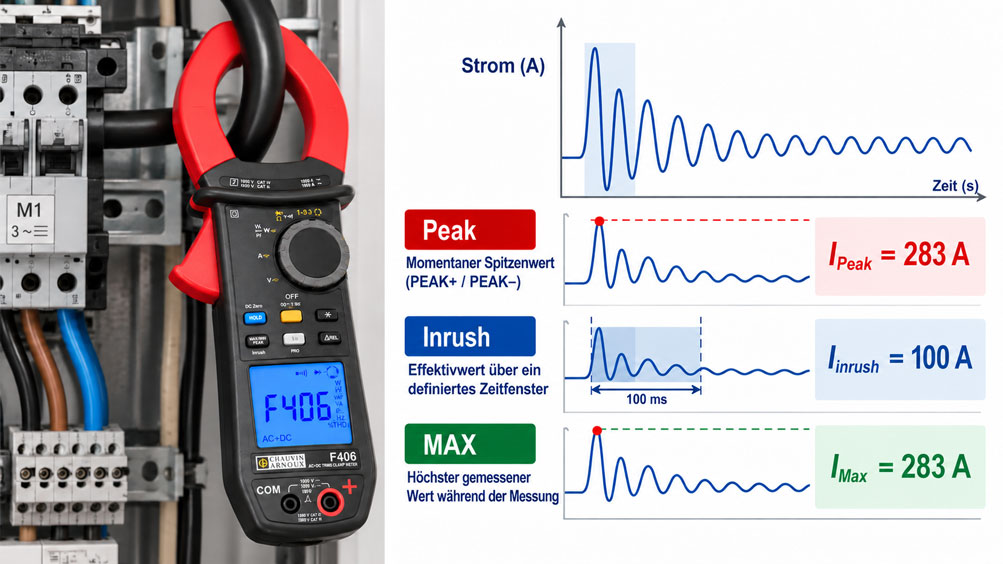
An electric motor operates with a normal running current, yet the circuit breaker occasionally trips when it is switched on. During normal measurement, a clamp meter displays only a stable current value. When the Peak function is activated, a much higher current suddenly appears. The Inrush function, however, produces another value. Which of these actually represents the inrush current?
The answer depends on the measurement method. A clamp meter can display the instantaneous peak value, an RMS value over a defined time window or the highest value recorded during an ongoing measurement. These quantities can differ considerably, particularly with short-duration, asymmetrical or heavily distorted current waveforms. Two technically sound measuring instruments may therefore produce different results during the same switching event.
When troubleshooting motors, transformers, switched-mode power supplies and other electrical loads, the measurement function, measurement window, trigger conditions and current waveform must be considered together. This technical article explains the differences between Peak, Inrush and MAX, provides an example of RMS calculation and describes how to measure inrush currents safely, reproducibly and with the appropriate clamp meter.
Table of Contents
- Define the Measurement Task Before Switching On
- Why Different Current Waveforms Occur During Switching
- How a Clamp Meter Measures Current
- Distinguish Between Peak, Inrush, MAX and True-RMS
- What the True RMS Value Means During Switching
- Correctly Interpret Peak Values and Crest Factor
- Understand the Measurement Window and Its Timing Effects
- Calculation Example: One Starting Event, Different Measured Values
- Correctly Set the Trigger, Threshold and Starting Point
- Position the Clamp Meter Around the Correct Conductor
- Observe Measurement Categories and Electrical Cabinet Safety
- Correctly Measure AC, DC and Superimposed Current Components
- Evaluate Starting Currents of Electric Motors
- Understand Transformer Inrush Currents
- Investigate Power Supplies and Capacitive Inrush Currents
- Compare Inrush Currents in Three-Phase Systems
- When an Oscilloscope or Data Logger Is Required
- Perform a Reproducible Inrush Current Test
- Correctly Evaluate Measured Values Against Fuses and Protective Devices
- Consider Measuring Range, Bandwidth and Measurement Uncertainty
- Identify Typical Measurement Errors and Misinterpretations
- Suitable Clamp Meters from ICS Schneider
- Conclusion: Always Evaluate the Measured Value Together with Its Time Basis
- Frequently Asked Questions About Measuring Inrush Current with Clamp Meters
1. Define the Measurement Task Before Switching On
Before measuring inrush current, it is important to clarify which technical question needs to be answered. Is the objective to detect a very short current peak immediately after switching on, to determine the RMS value during motor acceleration, or to establish how long the load takes to reach its normal operating condition?
This distinction matters because different measurement functions capture different characteristics of the current waveform. Peak measurement is suitable for investigating short-duration instantaneous peaks. Depending on the instrument, an Inrush function measures the current over a defined time window. A MAX recording over a longer period, by contrast, can reveal an unusually high current during operation.
When troubleshooting a protective device that trips during switching, both the magnitude and duration of the current surge may be relevant. For a motor, the starting time may also be decisive. When investigating a power supply, the first brief current peak may be more important than the current several hundred milliseconds later.
The measurement task should therefore specify at least the type of load, expected current range, supply type, approximate duration of the event and the information required. Only then can the appropriate measurement function and test instrument be selected.
2. Why Different Current Waveforms Occur During Switching
Electrical loads do not necessarily draw the same current during switching as they do in steady-state operation. The cause depends on their electrical and mechanical design.
When an induction motor is started directly from the mains, its rotor is initially stationary. The electrical conditions therefore differ considerably from operation at rated speed. During acceleration, slip, current consumption and torque change. The elevated current may persist throughout a substantial part of the starting phase.
In transformers, high inrush currents can result from factors including the switching instant within the mains voltage cycle and residual magnetisation of the magnetic core. The current waveform may be strongly asymmetrical and contain significant transient components.
In switched-mode power supplies and other electronic loads, charging DC-link capacitors can produce a short current surge. Current-limiting circuits, precharge resistors and suitable active inrush current limiting systems influence its magnitude and duration.
These processes produce different current waveforms. A motor may draw an elevated RMS current over a relatively long period, while a capacitive switching event may generate a very high but considerably shorter current pulse. There is therefore no single measured value that completely describes every inrush event.
3. How a Clamp Meter Measures Current
A clamp meter measures the magnetic field generated by the current flowing through the enclosed conductor. Depending on the sensing technology, measurement may be performed using a current transformer, Hall-effect sensor or flexible Rogowski coil with suitable evaluation electronics.
Conventional current transformers are suitable for alternating currents within their specified frequency range but cannot measure continuous direct current. Depending on their design, Hall-based measurement systems can measure both DC and AC currents. Rogowski coils are suitable for time-varying currents and require appropriate signal conditioning.
The sensor type and electronics determine the measuring range, measurement bandwidth, response characteristics and possible overload behaviour at high current peaks, among other properties.
For correct measurement, the clamp meter must surround the intended conductor. If the outgoing and return conductors are enclosed together, their magnetic effects can largely cancel each other out. This is unsuitable for normal load current measurement, although it is deliberately used in certain differential or residual current measurements.
The position of the conductor within the clamp opening can also influence measurement deviation. Centring the conductor according to the manufacturer’s instructions, ensuring that the jaws are fully closed and maintaining sufficient distance from adjacent conductors carrying high currents all contribute to reproducible results.
4. Distinguish Between Peak, Inrush, MAX and True-RMS
The function labels on clamp meters may look similar even though they refer to different measured quantities or acquisition methods. The distinction between instantaneous peak values and RMS values calculated over a period of time is particularly important.
| Measurement Function | Measured Quantity | Typical Application | Important Limitation |
|---|---|---|---|
| Normal True-RMS measurement | RMS current value according to the instrument’s measurement method | Operating current and sufficiently stable load conditions | Short switching transients may not be captured adequately because of display updates or averaging |
| MAX / MIN | Highest or lowest measured value recorded within the active measurement function | Monitoring load changes and sustained overcurrents | Acquisition and averaging times depend on the instrument |
| PEAK+ / PEAK− | Positive or negative instantaneous peak value | Analysis of short current peaks and asymmetrical current waveforms | Measurement bandwidth and minimum detectable pulse duration limit the result |
| INRUSH / TrueInrush | Instrument-specific event measurement, frequently an RMS value over a defined time window | Inrush and motor starting currents | Trigger conditions, measurement windows and calculations vary between instruments |
| Transient or waveform recording | Time-dependent current waveform with defined sampling | Analysis of current peaks, duration, repetition and waveform behaviour | Suitable bandwidth, sampling rate, memory depth and safe measurement equipment are required |
A common practical mistake is to consider MAX and PEAK equivalent. On many instruments, MAX displays the highest RMS value determined during a measurement. PEAK, on the other hand, describes the highest or lowest instantaneous value of the recorded signal.
An Inrush function may also provide both types of information. For example, the manufacturer’s operating instructions for the Chauvin Arnoux F205 describe TrueInrush acquisition over 100 ms. The recorded RMS value can then be displayed along with separate PEAK+ and PEAK− values.
The exact meaning of a measurement function must therefore always be checked against the instrument’s operating instructions. The label Inrush alone guarantees neither a specific measurement window nor detection of the absolute peak value during the entire starting event.
5. What the True RMS Value Means During Switching
The RMS value of a current describes its equivalent thermal effect compared with direct current under corresponding conditions. For an arbitrary current waveform i(t) over the considered time interval T, the following applies:
IRMS = √[(1/T) · ∫ i²(t) dt]
The integration extends over the defined measurement window T. The essential principle is that the instantaneous current values are first squared, then averaged over time, and finally the square root is calculated.
For a purely sinusoidal AC waveform without a DC component, a simple relationship exists between the peak value and RMS value. However, this condition is frequently not met during inrush transients.
A True-RMS measurement method is therefore particularly important when the current waveform deviates from an ideal sine wave. Nevertheless, True-RMS always describes the RMS value under the defined measurement conditions and within the bandwidth of the instrument.
During a rapidly changing switching event, the result also depends on the period over which the measurement is performed. An RMS value calculated over the first 20 ms may be considerably higher than one calculated over 100 ms or an entire second.
The True-RMS designation alone therefore does not guarantee adequate inrush current measurement. In addition to the calculation method, the time-dependent acquisition method must also be suitable.
6. Correctly Interpret Peak Values and Crest Factor
The Peak value represents an instantaneous peak of the current waveform. On suitably equipped clamp meters, positive and negative peak values are displayed separately as PEAK+ and PEAK−.
For an ideal sinusoidal current without a DC component:
IPeak = √2 · IRMS ≈ 1.414 · IRMS
However, this relationship does not apply universally to switching events. If the current is heavily distorted, contains a DC component or reaches high values only briefly, the ratio between peak and RMS values may differ considerably.
This ratio is known as the crest factor:
CF = IPeak, magnitude / IRMS
For a meaningful calculation, the peak and RMS values must refer to the same signal and time interval. This relationship is particularly important during transient switching events.
A high crest factor can also limit the measurement capability of a clamp meter. Even if the RMS value lies within the specified measuring range, the instantaneous peak may exceed the permissible input range.
A clamp meter with a PEAK function is therefore only suitable for the intended task if its measuring range, crest factor capability, bandwidth and specified acquisition time match the expected event.
Furthermore, the Peak value is not automatically the quantity that completely describes the thermal loading of a device or the tripping behaviour of a protective device. Both the magnitude and time-dependent profile of the current must be considered.
7. Understand the Measurement Window and Its Timing Effects
The measurement window determines the period over which an instrument evaluates the current waveform to produce a particular measured value. It is therefore one of the most important factors when interpreting inrush current.
At a mains frequency of 50 Hz, one complete cycle lasts 20 ms. A measurement window of 100 ms therefore covers five complete mains cycles.
According to its operating instructions, the Chauvin Arnoux F205 uses a 100 ms acquisition interval for the TrueInrush function after the trigger has been activated. The RMS value for this interval is displayed, and PEAK+ and PEAK− can also be accessed. This is a specific instrument function, not a universal definition for all Inrush clamp meters.
Within a longer RMS measurement window, short current peaks are evaluated together with the remaining current components. A very high current lasting only a few milliseconds may therefore produce a considerably lower RMS value over 100 ms.
When a Peak value is measured, the emphasis is instead on the maximum instantaneous excursion. Here too, the instrument must acquire the signal quickly enough to avoid missing or underestimating the pulse.
For a motor whose starting process lasts several seconds, a 100 ms window describes only a short part of the entire starting phase. It does not provide complete information about how long the elevated current persists.
The measurement window and the timing of acquisition must therefore be matched to the technical question. Very short switching transients require different measurement methods from a prolonged motor starting process.
8. Calculation Example: One Starting Event, Different Measured Values
A simplified model considers a switching event within a measurement window of 100 ms. During the first 20 ms, the RMS current is 200 A. During the following 80 ms, the RMS current is 50 A.
For this model, the two time intervals are described by their respective mean-square current values. The RMS value over the complete 100 ms window is therefore:
IRMS,100ms = √[(200² · 0.020 + 50² · 0.080) / 0.100]
IRMS,100ms = 100 A
Although the current reaches an RMS value of 200 A during the first interval, evaluation over the complete 100 ms produces only 100 A.
The instantaneous Peak value is not yet known. Determining it would require the actual waveform within the individual intervals to be recorded. For an ideal sinusoidal waveform with an RMS value of 200 A, the corresponding peak would be approximately 283 A. For an asymmetrical switching transient, it could differ considerably.
The example illustrates three different quantities: The highest RMS value within an individual interval is 200 A, the RMS value over 100 ms is 100 A, and the actual peak depends on the waveform, which has not been specified in detail.
These figures are deliberately idealised calculation values and are not specifications of any instrument. During real switching events, current magnitude and waveform frequently change continuously.
Comparing several clamp meters is therefore only meaningful when the measured quantity and measurement window used by each instrument are known.
9. Correctly Set the Trigger, Threshold and Starting Point
The Inrush function must detect when a switching or overcurrent event begins. Many measuring instruments use a trigger that starts acquisition when a defined current threshold is exceeded.
If the trigger threshold is too high, a relevant switching event may not be detected. A threshold that is too low can cause the instrument to trigger on ordinary load fluctuations or electrical interference.
The Chauvin Arnoux F205 provides an example of instrument-specific behaviour. Its operating instructions describe a fixed trigger threshold of 6 A for a system that is initially not carrying current. Where a current is already flowing, the designated configured threshold is used.
These values apply to the described F205 function. Other clamp meters have different trigger conditions and threshold values.
Timing is equally important. If the measurement function is only activated after the load has been switched on, the relevant inrush transient may already have passed. The instrument must therefore be placed in the appropriate ready state before the intended switching event.
For recurring operating events, it must also be established whether only one starting event is to be recorded or whether the instrument should wait for another overcurrent event afterwards. Storage and reset functions can vary between models.
An indicated Inrush value should therefore always be documented together with the selected mode, trigger behaviour and associated time basis.
10. Position the Clamp Meter Around the Correct Conductor
For conventional load current measurement, the clamp meter is placed around exactly the conductor whose current is to be measured. In a single-phase supply, this is typically the relevant live conductor. In a three-phase system, one phase can be measured individually.
If an entire connecting cable containing both outgoing and return conductors is enclosed, the magnetic fields generated by currents flowing in opposite directions largely cancel each other out. The result is therefore unsuitable for normal inrush current measurement.
A similar situation occurs when all three live conductors in a balanced three-phase system are enclosed together. Under ideal conditions, the vector sum of their currents is zero. To measure the inrush current of an individual phase, only the corresponding conductor is enclosed.
The conductor should be positioned within the clamp opening according to the manufacturer’s instructions. The jaws must close completely. Contaminated or damaged contact surfaces on the jaws can cause additional errors with certain measuring principles.
In confined electrical cabinets, conductors must not be bent apart under impermissible mechanical stress or removed from their safe routing solely for measurement purposes.
For recurring measurements, a suitable permanently provided measurement access point may be useful. The selection and installation of such arrangements must comply with electrical safety requirements.
11. Observe Measurement Categories and Electrical Cabinet Safety
Inrush current measurements are frequently performed on electrical installations with hazardous voltages and high available short-circuit currents. Using a clamp meter does not eliminate these hazards.
Before measurement, the electrical installation, access to the conductor and suitability of the measuring instrument must be assessed. Measurements on energised parts may only be performed by appropriately qualified personnel using a suitable safe working procedure.
The measurement category of the instrument must be appropriate for the measurement location. CAT III typically applies to measurements within fixed electrical installations, such as distribution boards and permanently installed machinery. CAT IV applies to the supply area or origin of a low-voltage installation.
The measurement category must always be considered together with its rated voltage. A specification such as CAT IV 600 V has a different meaning from an isolated 600 V rating without a measurement category.
IEC 61010-2-032 specifies particular safety requirements for hand-held current sensors used for electrical measurement and testing. The instrument markings, operating instructions and applicable occupational safety requirements must also be observed for the specific application.
Particularly important factors include the condition of the clamp meter, permissible proximity to live parts, available finger guards and any required personal protective equipment.
Test leads and additional accessories must also be suitable for the relevant voltage and measurement category. An accessory with a lower permissible category can limit the safe operating range of the complete measurement combination.
An electrical cabinet must not be opened or modified using improvised methods solely to perform an inrush current measurement. The required measurement point must provide safe access and an appropriate working procedure.
12. Correctly Measure AC, DC and Superimposed Current Components
Not every clamp meter can measure all types of current. An instrument designed exclusively for AC measurement is not automatically suitable for measuring DC or a superimposed DC component.
A purely AC measuring instrument does not detect a continuous DC component as such. A DC-capable instrument with suitable sensing technology can also measure direct current. On appropriately designed instruments, AC+DC functions allow a signal containing both alternating and direct current components to be evaluated.
The actual functions available must be checked for the relevant operating mode. For example, according to its operating instructions, the Chauvin Arnoux F205 permits TrueInrush measurements in AC or DC mode, but not in combined AC+DC mode.
For DC measurements, zero-point correction may be required. Hall-based measurement systems are affected by factors including residual magnetisation and zero-point shifts. The relevant correction must be performed according to the instrument’s specified procedure before the conductor to be measured is enclosed.
Power supplies, frequency converters and other power electronic equipment can produce current waveforms that differ considerably from a sinusoidal AC waveform. In such cases, the measurement bandwidth and permissible frequency ranges of the instrument are particularly important.
A clamp meter that reliably measures operating current at 50 Hz does not automatically capture arbitrarily fast current pulses or high-frequency switching components accurately.
13. Evaluate Starting Currents of Electric Motors
When an electric motor is switched on, the current waveform depends significantly on the motor type, starting method, mechanical load and supply voltage.
When an induction motor is started directly from the mains, high currents can occur while the rotor has not yet accelerated sufficiently. The starting duration depends on factors including the load, moment of inertia and available accelerating torque.
An Inrush measurement can capture the current immediately after switching on. However, diagnosing a machine with excessive mechanical resistance or a motor with an unusually long starting time may require additional time-dependent recording.
A high initial current alone does not prove that the motor is defective. The decisive question is whether the magnitude and duration of the starting current are plausible under the actual operating conditions.
The starting method also changes the current waveform. Star-delta starting can produce different current conditions compared with direct-on-line starting. Additional transients may occur during switching between the operating configurations.
Soft starters reduce or control the voltage during starting and thereby influence current and torque. Frequency converters produce different current waveforms, whose evaluation depends on the measurement location and measuring method used.
For meaningful diagnosis, the starting method, load condition, supply voltage, measured phase and starting duration should therefore be documented.
14. Understand Transformer Inrush Currents
When a transformer is energised, its magnetising current can briefly reach very high values. The time-dependent profile depends on factors including the switching instant within the voltage waveform and the residual magnetic state of the core.
Under certain conditions, the current may be strongly asymmetrical and contain a considerable transient component over several cycles. The first current peak can then differ substantially from a steady-state sinusoidal current.
For this investigation, the Peak function can provide important additional information. An Inrush measurement, on the other hand, describes the RMS value or other instrument-specific quantity recorded within the relevant time window.
A single switching event is not necessarily representative for transformers. The magnetic condition may change after switching off. Consequently, different current peaks may occur during the next energisation.
A defined measurement sequence is required for reproducible investigations. The switching state, power supply, energisation conditions and possible protective measures must all be considered.
If the exact time-dependent waveform or interaction with a protective device needs to be investigated, waveform recording may be necessary. An individual Peak or Inrush value is then insufficient for a complete assessment.
15. Investigate Power Supplies and Capacitive Inrush Currents
Very short current peaks can occur when switching on switched-mode power supplies, electronic controllers and other loads containing DC-link capacitors. One cause is the charging process of initially discharged capacitors.
The magnitude of the current peak depends on the mains impedance, switching instant, internal current limiting system and instantaneous state of charge.
A short-duration high Peak value therefore does not necessarily mean that the RMS current over 100 ms or one second will be correspondingly high.
Particularly with switched-mode power supplies, several switching events in quick succession can produce different measured values. Components used for inrush current limiting, such as certain temperature-dependent resistors, may still be warm between starts.
For reliable comparative measurements, the time since the previous shutdown, thermal condition and switching conditions should therefore be recorded.
If several power supplies are switched on simultaneously, for example, their inrush currents may overlap. Staggered switching can alter the loading but must remain compatible with the electrical and functional requirements of the installation.
Measuring the current peak alone does not establish whether an existing protective component is correctly rated. Additional information about the time-dependent waveform, energy loading and protection concept is required.
16. Compare Inrush Currents in Three-Phase Systems
In a three-phase load, the current waveforms in the individual live conductors may differ during switching. This applies particularly to asymmetrical transient events or special switching conditions.
A single clamp meter normally measures only the current in the conductor currently enclosed. If L1 is measured first and L2 afterwards, these measurements represent two different starting events.
Especially with transformers or other loads whose inrush current depends on the switching phase angle, the conditions can differ between starts. Values measured sequentially on individual phases must therefore not automatically be interpreted as a simultaneous three-phase current distribution.
For basic diagnosis, it can nevertheless be useful to investigate the three phases sequentially under conditions that are as similar as possible. The significance of the results must then be interpreted accordingly.
However, if the actual current unbalance during the same switching event is to be analysed, a suitable multichannel measurement with synchronised acquisition is required.
Neutral conductor current may also be relevant depending on the connection arrangement and load. However, the current quantity being investigated must be clearly defined. The combined current of several enclosed conductors is not equivalent to the inrush current of an individual live conductor.
17. When an Oscilloscope or Data Logger Is Required
A clamp meter with an Inrush function is sufficient for many service applications. It displays a defined measured value for the switching event and can therefore be very useful for troubleshooting.
However, if the exact time-dependent current waveform is required, more advanced recording may be necessary. Examples include investigating several successive current peaks, a prolonged acceleration phase or the timing relationship between current and voltage.
A suitable oscilloscope with an appropriately rated current sensor or a corresponding transient recorder can capture the waveform with defined time resolution. Selection must match the current magnitude, frequency components, required recording duration and electrical safety requirements.
Conventional data loggers, by contrast, often use much longer recording intervals. A measurement interval of one second cannot fully capture a switching event lasting only a few milliseconds.
Even where an instrument includes an integrated data logger, a distinction must therefore be made between normal long-term recording and special event or Inrush acquisition.
An example is the HT Instruments HT9023 offered by ICS Schneider. Among other functions, it combines Dynamic-INRUSH with data logging. However, normal recording with a selectable integration interval must not be confused with the time resolution of the separate inrush current function.
When selecting an instrument, it must therefore be clear whether a single inrush current value, a time-dependent waveform or synchronised recording of several electrical quantities is required.
18. Perform a Reproducible Inrush Current Test
A systematic test procedure improves the comparability of measured values. The essential requirement is that the same load is investigated under traceable conditions and that the clamp meter is correctly prepared before the switching event.
The following procedure assumes a suitable, safely accessible measurement point and that the work is performed by qualified personnel.
- Define the measurement task: Establish whether a peak value, Inrush RMS value, starting duration or time-dependent current waveform is required.
- Assess the electrical installation: Check the voltage, measurement category, hazards and safe access to the conductor to be measured.
- Select the clamp meter: Ensure a suitable current range, AC/DC capability, measurement bandwidth and required special functions.
- Prepare the measurement point: Identify the intended individual conductor and position the clamp meter using the approved safe working procedure.
- Set the measurement mode: Activate the Inrush, Peak or recording function according to the test objective.
- Check the trigger: Verify the threshold and ready state, configuring them according to the instructions if necessary.
- Document the starting conditions: Record the operating condition, load, supply voltage and time since the previous start, where relevant.
- Perform the switching event: Switch on the load under the intended and safely controlled conditions.
- Record the measured values: Document the Inrush value, PEAK+ and PEAK− where available, and the measurement settings used.
- Repeat the measurement: Where safe and operationally permissible, perform several comparable starts and evaluate any differences.
- Evaluate the results: Compare the measured values with load specifications, starting conditions and protective device behaviour.
- Restore the measurement point: Remove the test setup according to the specified procedure and verify the safe condition of the installation.
Conditions must remain as comparable as possible during repeated measurements. This applies, for example, to the mechanical loading of a motor or the thermal condition of an inrush current limiting device.
If repeated switching could subject the installation, load or protective device to impermissible stress, the test sequence must not be continued merely to obtain additional measured values.
The test is intended for diagnosis under safe conditions. It does not authorise bypassing protective functions or creating impermissible switching conditions.
19. Correctly Evaluate Measured Values Against Fuses and Protective Devices
A high inrush current can cause fuses or other protective devices to operate when a load is started. However, whether this occurs does not depend solely on the highest current value.
Depending on their design and tripping range, miniature circuit breakers use thermal and magnetic tripping mechanisms. The magnitude and duration of the current, together with the specific tripping characteristic, are relevant to the assessment.
For fuses, the time-current characteristic and, where applicable, energy loading play an important role. The integral of current squared over a particular interval can generally be expressed as:
I²t = ∫ i²(t) dt
The integration is performed over the relevant time interval. A single Peak value or an Inrush value without a clearly specified measurement method is insufficient to determine the actual operating behaviour of a protective device in general.
The properties of the supply cable, available short-circuit current, type of load and other protective requirements must also be considered.
It is particularly important to distinguish between an overcurrent protective device and a residual current device. An RCD responds to the relevant differential or residual currents, not simply to a high balanced load current. However, switching-related leakage or differential currents can represent a separate cause of unwanted tripping.
A protective device that trips must therefore not simply be replaced with a higher-rated version because a high inrush current has been measured. Cable sizing, protective conditions, selectivity and permissible operating conditions must be professionally verified.
A more detailed discussion is provided in the ICS technical article Measuring Inrush Current: Why Protective Devices Trip During Starting.
20. Consider Measuring Range, Bandwidth and Measurement Uncertainty
The measurement accuracy of a clamp meter depends on the measurement type and operating conditions. A data sheet may specify different accuracy values for normal AC/DC current measurement, Peak acquisition and Inrush measurement.
The accuracy of the normal operating current range must therefore not automatically be applied to a very short switching transient.
Relevant influencing factors include measuring range, resolution, frequency range, crest factor, conductor position, neighbouring magnetic fields, temperature and, where applicable, zero-point behaviour.
The time-dependent acquisition range also plays a role. A fast Peak detector can capture a different current component from an RMS display with a slower update rate.
At high current peaks, particular attention must be paid to possible input overload. An instrument may operate within its permissible RMS current range while still reaching the limits of its acquisition system because of an excessively high instantaneous peak.
When comparing a measured value with another test instrument, the same measured quantity and, as far as possible, equivalent timing conditions must therefore be used. A Peak value must not be directly interpreted as a measurement deviation relative to an Inrush RMS value.
The scope of calibration must also be distinguished accordingly. Calibration of steady-state AC current measurement does not automatically confirm the full accuracy of event acquisition for arbitrary switching transients.
If the inrush current function must be verified with a defined uncertainty, a suitable test method and appropriately qualified reference are required. The test report must clearly describe the scope and the signal waveforms or timing conditions considered.
For routine maintenance diagnostics, a suitable measurement function used in a traceable manner is often sufficient. Detailed comparative or verification measurements, however, may require more demanding specifications for time base, calibration and measurement uncertainty.
21. Identify Typical Measurement Errors and Misinterpretations
Many errors in inrush current measurement are caused not by a defective sensor, but by an unsuitable measurement function, incorrect trigger conditions or unclear identification of the current quantity being measured.
The following table shows common observations and suitable checks.
| Observation | Possible Cause | Suitable Check |
|---|---|---|
| The clamp meter only shows normal operating current during starting | The inrush transient is not captured by the normal display update rate or averaging | Activate an appropriate Inrush or Peak function before starting |
| The Peak value is considerably higher than the Inrush value | An instantaneous peak is being compared with an RMS value calculated over a time window | Distinguish between measured quantities, window duration and waveform shape |
| The Inrush function does not trigger | Incorrect trigger setting, insufficient current or measurement activated too late | Check the ready state and instrument-specific trigger threshold |
| The measurement shows almost zero although the load is drawing current | Several conductors enclosed together or incorrect measurement point selected | Identify and correctly enclose the intended individual conductor |
| The measured value differs significantly between several starts | Different switching phase angle, thermal condition, load or magnetic remanence | Document starting conditions and establish a reproducible measurement sequence |
| A DC current value is indicated without a load | Zero-point offset or residual magnetisation | Perform DC zero-point correction according to the manufacturer’s instructions |
| Measured values at high current peaks appear implausible | Input overload, unsuitable measuring range or limited crest factor capability | Check Peak limits, acquisition range and instrument specifications |
| A prolonged starting phase appears as only one Inrush value | The Inrush window captures only part of the event | Use suitable time-dependent waveform recording |
| Stored data do not contain short-duration current peaks | Unsuitable recording interval or measurement bandwidth | Check event acquisition separately from normal data logging |
| A protective device trips even though the Inrush value appears normal | Very short current peak, another fault or insufficient time resolution | Investigate protective device behaviour, Peak, current waveform and, where appropriate, residual current separately |
These observations are diagnostic indications rather than complete fault determinations. For example, a high current peak may be technically normal, while the actual problem lies in inadequate coordination between the load, starting method and protection concept.
An appropriate troubleshooting procedure therefore begins by identifying which current quantity was actually measured. Only then should the electrical cause, time-dependent waveform and effect on the installation be evaluated.
22. Suitable Clamp Meters from ICS Schneider
22.1 Chauvin Arnoux F201: TrueInrush for Basic Inrush Current Measurement
The Chauvin Arnoux F201 multimeter clamp is suitable for typical electrical measurement and testing tasks in electrical installation and maintenance. It features an AC current measuring range up to 600 A and a clamping diameter of 34 mm.
Its functions include TrueInrush as well as HOLD, MIN and MAX. The F201 is therefore particularly useful when the inrush or starting current of a load needs to be measured under suitable conditions.
The specified measurement category is CAT IV 600 V. The permissible current and voltage limits and the relevant manufacturer instructions must also be observed in the specific application.
For tasks requiring additional positive and negative Peak values or DC current measurement, a suitably equipped model must be selected.
22.2 Chauvin Arnoux F205: Separate Evaluation of Inrush and Peak Values
The Chauvin Arnoux F205 multimeter clamp is particularly suitable for measurement tasks involving both inrush current and short-duration current peaks or different types of current.
It supports AC and DC current measurement up to 600 A AC and 900 A DC respectively, and has a clamping diameter of 34 mm. The F205 offers TrueInrush as well as MIN, MAX, PEAK+ and PEAK− functions.
According to the operating instructions, the TrueInrush function captures an event over 100 ms and evaluates it as an RMS value. Positive and negative Peak values can then be displayed separately.
This makes the F205 particularly suitable for distinguishing a short-duration instantaneous peak from an Inrush RMS value in practical applications. The instrument-specific limitations of TrueInrush acquisition must nevertheless be observed.
22.3 Chauvin Arnoux F406: Advanced Current Measurement in Industrial Environments
The Chauvin Arnoux F406 multimeter clamp is designed for more demanding electrical measurements in industrial installations. It has a clamping diameter of 48 mm and supports current measurement up to 1000 A AC and 1500 A DC.
Its functions include TrueInrush, PEAK+ and PEAK−, as well as additional analysis functions for electrical quantities, power and harmonic distortion.
The larger clamp opening and extended current measuring range are particularly useful for appropriately sized electrical installations. Here too, the permissible operating conditions and separate specifications for the respective measurement functions are decisive.
When selecting the instrument, it is important to distinguish between applications requiring only a starting current value and those requiring additional analysis of operating current, peak values and other electrical parameters.
22.4 HT Instruments HT9023: Inrush Current and Advanced Electrical Analysis
The HT Instruments HT9023 is a TRMS power analysis clamp meter for AC/DC measurements up to 1000 A. In addition to general current and voltage measurement, it supports power analysis, harmonic measurement, data recording and a separate Dynamic-INRUSH function.
The HT9023 is therefore suitable for applications in which switching events need to be investigated in conjunction with other electrical operating quantities.
The normal data logging function has its own recording intervals and must be distinguished from dedicated inrush current acquisition. When investigating very short transient events, it is therefore necessary to determine which function provides the required time resolution.
The measurement categories are CAT IV 600 V and CAT III 1000 V. The specific electrical application must remain within the approved operating limits.
Further suitable clamp meters, multimeter clamps and power analysers are available from ICS Schneider in the Electrical Test and Measurement Instruments category and under Multimeter Clamps / AC/DC.
23. Conclusion: Always Evaluate the Measured Value Together with Its Time Basis
When measuring inrush current, the magnitude of the displayed value alone does not determine how meaningful the measurement is. Peak, Inrush and MAX capture different characteristics of the current waveform. An instantaneous peak may be considerably higher than the RMS value over a longer measurement window without either result necessarily being incorrect.
When troubleshooting motors, transformers, power supplies and electrical installations, the measurement type, measurement window, trigger and starting conditions must therefore be compatible. Knowledge of the instrument-specific Inrush function is particularly important.
A high inrush current may be part of normal operating behaviour. The duration, electrical supply, load characteristics and existing protection concept must also be considered in the technical assessment.
For straightforward service tasks, a suitable TrueInrush clamp meter may be sufficient. However, if individual current peaks, prolonged starting profiles or several electrical quantities need to be investigated simultaneously, more advanced event or waveform recording is useful.
Define the measurement task → Select the clamp meter and measuring range → Activate the appropriate measurement function → Check the trigger and measurement window → Safely measure the individual conductor → Capture the switching event → Evaluate Peak and RMS values separately → Assess the current waveform and protection concept → Document the results
The most important practical principle is therefore: An inrush current value can only be interpreted unambiguously when it is known which electrical quantity it represents, over what time period it was acquired and under what conditions the switching event occurred.
24. Frequently Asked Questions About Measuring Inrush Current with Clamp Meters
24.1 What Is the Difference Between Peak and Inrush?
Peak represents the instantaneous peak value of a current signal. Inrush refers to an instrument-specific inrush current measurement, frequently an RMS value over a defined measurement window. The two values can differ considerably during the same switching event.
24.2 Which Function Should I Use to Measure Motor Starting Current?
An appropriate Inrush or TrueInrush function is useful for initially capturing the elevated current during starting. If the complete starting duration, several current peaks or the time-dependent waveform is required, additional suitable recording is necessary.
24.3 Why Does the Peak Function Show a Higher Current Than the Inrush Function?
The Peak function captures an instantaneous peak value. Depending on the instrument, the Inrush function calculates an RMS value over a defined time interval. High current components lasting only briefly can produce a substantially lower RMS value when averaged over time.
24.4 Are Peak and MAX the Same on a Clamp Meter?
No. On many instruments, MAX represents the highest RMS value captured by the selected measurement function. PEAK+ and PEAK−, by contrast, capture positive and negative instantaneous peak values. The exact meaning must be taken from the operating instructions.
24.5 Why Is the Measurement Window Important for Inrush Current Measurement?
The measurement window determines the period over which an RMS value is calculated. During a short current surge, a shorter window can produce a higher RMS value than a longer window. The relevant window duration must therefore be known when comparing measurements.
24.6 What Does an Inrush Measurement Window of 100 ms Mean?
At 50 Hz, an interval of 100 ms corresponds to five complete mains cycles. If an instrument calculates the RMS value over this interval, all current components captured within it influence the result. The exact acquisition timing and trigger logic depend on the instrument.
24.7 Is a Normal True-RMS Clamp Meter Sufficient for Inrush Current Measurement?
Not necessarily. True-RMS describes the method of calculating the RMS value, but does not guarantee suitable acquisition of very short events. A dedicated Inrush, Peak or event function should be available for targeted inrush current measurement.
24.8 Why Does the Inrush Function Sometimes Fail to Trigger?
Possible causes include an excessively high trigger threshold, unsuitable measurement mode, insufficient current or activation of the function only after switching on. The trigger procedure must be checked for the specific clamp meter.
24.9 Must the Clamp Meter Be Activated Before Switching On?
Yes. For event-triggered inrush current measurement, the instrument must be placed in the appropriate ready state before the relevant switching event. Otherwise, the short current surge may already have passed before acquisition begins.
24.10 Can I Measure Inrush Current Around an Entire Connecting Cable?
This is unsuitable for normal load current measurement if the outgoing and return conductors are enclosed together. Their magnetic effects largely cancel each other out. The intended individual conductor must be measured.
24.11 Can an AC Clamp Meter Also Capture DC Inrush Currents?
A purely AC clamp meter is not suitable for measuring continuous direct current. An appropriately equipped instrument must be used for DC or combined current components. Whether the particular Inrush function supports that type of current must be checked separately.
24.12 Why Do Inrush Currents Differ Between Several Starts?
For transformers, the residual magnetic state and switching instant may be relevant. For power supplies, capacitor charge and the thermal condition of the inrush current limiter may influence the result. For motors, the load and starting conditions also affect the measured current.
24.13 How Do I Measure the Inrush Current of a Three-Phase Motor?
A conventional single clamp meter measures the current in one live conductor. Additional phases can be measured under conditions that are as similar as possible for comparison. Simultaneous assessment of all three phases requires a suitable multichannel measurement system.
24.14 Can a Clamp Meter Measure Very Short Current Peaks?
This depends on the measurement bandwidth, Peak acquisition time and permissible peak current of the instrument. A general current measurement function is not always sufficient. Particularly fast transients may require a suitable current probe with an oscilloscope or transient recorder.
24.15 Is a High Peak Value Sufficient to Explain Why a Fuse Trips?
Not by itself. Protective devices respond to particular current and timing conditions according to their design and characteristics. The current magnitude, duration, protective device, cable conditions and complete protection concept must therefore be considered.
24.16 Can I Simply Install a Higher-Rated Fuse Because of a High Inrush Current?
No. Changing a protective device requires professional verification of cable protection, disconnection conditions, short-circuit conditions, selectivity and manufacturer requirements. A single inrush current value does not justify increasing the protective device rating.
24.17 Does the Inrush Current Function of a Clamp Meter Require Separate Calibration?
If a defined measurement uncertainty must be demonstrated for the Inrush or Peak function, the calibration scope must cover the corresponding measured quantity and time-dependent acquisition. Calibration of normal AC current measurement does not automatically confirm every characteristic of transient event acquisition.
24.18 What Information Does ICS Schneider Need for Selection?
The required information includes the type of load, supply voltage, mains frequency, AC/DC current type, expected operating and inrush currents, and approximate duration of the starting event. Available conductor dimensions, measurement category, accessibility of the measurement point and required measurement function must also be specified. For advanced analysis, requirements relating to Peak acquisition, Inrush measurement window, triggering, time-dependent recording, multichannel measurement and, where applicable, calibration are relevant.