


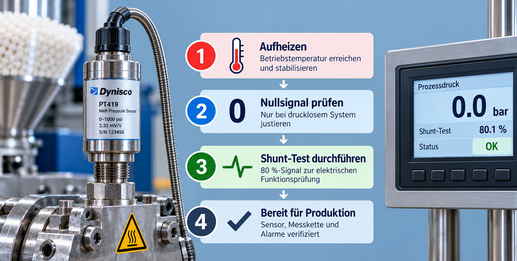
A reliable melt pressure signal is an essential requirement for the controlled start-up of extruders and other plastics processing equipment. However, after shutdowns, tooling changes or sensor maintenance, thermal influences, residual pressure, installation errors or electrical interference can lead to implausible measured values.
A Dynisco sensor should therefore be systematically checked before production starts. The recommended sequence is: Inspect the installation, allow the equipment to heat up sufficiently, ensure a pressure-free condition, check the zero signal, perform the shunt test and then monitor the measurement signal during controlled process start-up.
This technical article explains the individual steps, typical causes of errors and the limitations of electrical functional testing. It is intended for maintenance technicians, process engineers and users of melt pressure sensors in extrusion, plastics processing and materials testing.
Table of Contents
1. Why Sensor Testing Before Production Start-Up Is Important
Melt pressure sensors measure the pressure of highly viscous media at elevated temperatures. In extrusion systems, the measured values are used for process monitoring, quality assurance and evaluating operating conditions, among other purposes.
Errors can be particularly critical during equipment start-up. An incorrectly adjusted zero point affects the entire pressure indication. An incorrectly scaled signal produces inaccurate pressure values. A damaged diaphragm or an unsuitable mounting hole can permanently impair the sensor.
The start-up test should therefore answer three separate questions: Is the sensor mechanically and thermally ready for operation? Is its zero signal plausible? And does the electrical signal chain respond as expected to a defined test signal?
2. Operating Principle of Dynisco Melt Pressure Sensors
Many conventional Dynisco melt pressure transducers transmit the pressure force acting on the process diaphragm through a liquid-filled system to a strain-gauge sensing element. This element changes its electrical characteristics in response to pressure.
Depending on the series, the signal is provided as an mV/V bridge signal or, through integrated electronics, as a 4–20 mA signal, for example. Other sensor technologies and signal variants are also available.
Conventional mV/V technology requires a suitable excitation voltage and signal conditioning. Amplified transmitters, on the other hand, can be connected directly to suitable PLC or process control system inputs.
The permissible process temperature, output signal and available test functions must always be determined from the specifications of the particular Dynisco model.
3. The Correct Sequence for Start-Up Testing
The sequence of testing is essential. Performing zero adjustment during an unstable heating phase may only temporarily compensate for a temperature-related signal offset.
Performing a shunt test before checking the zero signal also makes interpretation more difficult if the signal processing is incorrectly scaled.
| Test Phase | Objective | Typical Error |
|---|---|---|
| Installation | Verify mechanical integrity | Contaminated mounting hole |
| Heating | Achieve thermally stable conditions | Starting the equipment too early |
| Pressure-free condition | Clearly evaluate the zero signal | Remaining melt pressure |
| Zero signal | Identify signal offset | Improper zero adjustment |
| Shunt test | Check electrical signal transmission | Interpreting the test signal as actual pressure |
| Process start-up | Check the plausibility of the dynamic pressure signal | Unnoticed pressure peaks |
Operational release should only be granted once all applicable test steps have been completed satisfactorily.
4. Checking the Mechanical Installation
The mechanical condition should be inspected before heating begins. This includes the sensor housing, process connection, plug connections and any existing capillary tubing.
For sensors with a flexible capillary, the tubing must not be crushed, kinked or subjected to excessive mechanical stress. The sensor housing must be mounted according to the manufacturer’s instructions and protected against excessive heating.
The installation position of the diaphragm is also important. Incorrect insertion depth can lead to mechanical stress or unfavorable contact with the melt.
Important: Do not screw sensors into solidified polymer residues, and never attempt to overcome installation problems by applying an arbitrarily higher tightening torque.
5. Inspecting the Mounting Hole and Sealing Surface
The mounting hole must match the sensor’s connection geometry. The thread, hole depth, clearance around the sensor tip and designated sealing surface are particularly important.
A defined 45° sealing surface is frequently used with common Dynisco 1/2-20 UNF connections. Other connection types may have different requirements.
Polymer residues in the mounting hole may prevent the sensor from seating correctly. This can cause leakage, mechanical stress or diaphragm damage.
Dynisco offers special cleaning tools and inspection gauges for this purpose. Cleaning should be performed according to the relevant tool instructions and under suitable thermal conditions.
The mounting hole should preferably be inspected during maintenance before reinstalling the sensor. An installed sensor that shows no abnormalities does not need to be removed solely for a daily start-up check.
6. Heating Phase and Temperature Stabilization
During heating, temperatures change at the sensor diaphragm, process connection and, where applicable, within the pressure transmission system. This can cause the zero signal to shift.
The displayed temperature of the heating zone does not necessarily prove that all polymer residues directly adjacent to the sensor diaphragm have completely melted.
Sufficient heat-soaking time must therefore be allowed before starting the extruder drive. The required time depends on factors including the polymer, equipment geometry, shutdown duration and temperature control.
A universally applicable value of, for example, 10 or 15 minutes would not be technically justified. The instructions provided by the equipment and sensor manufacturers, together with validated operating conditions, are decisive.
The zero signal should only be evaluated conclusively once the temperature and signal are sufficiently stable and the pressure-free condition has been confirmed.
7. Checking the Zero Signal and Pressure-Free Condition
The zero signal is the electrical output of the sensor at its defined zero-pressure point.
For a 4–20 mA gauge pressure transmitter scaled to 0–100% of its measuring range, the zero point normally corresponds to 4 mA. For an appropriately specified mV/V pressure transducer, the nominal zero output is close to 0 mV/V.
It is essential that the pressure condition corresponding to the zero point actually exists. For a gauge pressure sensor, this generally means zero differential pressure relative to ambient pressure.
An extruder may still contain trapped pressure even when the screw is stationary. An indication above zero must therefore not automatically be interpreted as a sensor fault.
Once a confirmed pressure-free condition has been established, the zero deviation can be compared with the permissible manufacturer and operational limits.
8. Practical Example of Signal Testing
8.1 Initial Data
A hypothetical Dynisco melt pressure transmitter has a gauge pressure measuring range of 0 to 350 bar and a linear 4–20 mA output signal.
For this example, it is assumed that the specific sensor version has a shunt simulation function at 80% of the measuring range. This function is not identical across all models.
8.2 Calculation Basis
The following equation applies to linear scaling:
p = (I – 4 mA) / 16 mA × 350 bar
The output signal at a specified pressure can be calculated accordingly:
I = 4 mA + (p / 350 bar) × 16 mA
8.3 Calculation
At 80% of the measuring range upper limit, the result is:
p = 0.80 × 350 bar = 280 bar
The corresponding nominal output signal is:
I = 4 mA + 0.80 × 16 mA = 16.8 mA
8.4 Additional Evaluation
Assume the sensor delivers 4.08 mA in a confirmed pressure-free condition. With the selected scaling, this results in a calculated pressure indication of 1.75 bar.
This value represents the indicated offset. Whether it is permissible can only be determined from the device-specific zero-point specification and operational requirements.
8.5 Comparison
During the shunt test, a current of 16.76 mA is measured as an example. With the assumed linear scaling, this corresponds to 279.13 bar or approximately 79.75% of the measuring range.
8.6 Summary of Results
| Test Condition | Expected Value | Measured Value | Evaluation |
|---|---|---|---|
| Pressure-free condition | 4.00 mA | 4.08 mA | Check offset |
| 80% shunt simulation | 16.80 mA | 16.76 mA | Deviation -0.04 mA |
| Calculated pressure indication during shunt test | 280.00 bar | 279.13 bar | Deviation -0.87 bar |
8.7 Interpreting the Results
The figures demonstrate that a small zero-point deviation and a small deviation in the shunt signal can be investigated separately.
However, an 80% shunt simulation does not necessarily correspond to an absolute output current of 16.8 mA. Depending on the device-specific circuitry and adjustment, the simulated signal may be referenced to the current zero point.
The exact expected value must therefore be obtained from the manufacturer’s instructions or a documented reference measurement. The example values do not represent manufacturer tolerances and do not justify automatic operational approval.
9. Performing Zero Adjustment Correctly
Zero adjustment is a form of adjustment. It changes the relationship between pressure and output signal and must not be confused with simply checking the zero point.
Before adjustment, the following conditions must be met: The equipment is in a safe condition, the required operating temperature has been reached, there is definitely no relevant process pressure present and the electrical supply is operating correctly.
On suitable Dynisco models, adjustment is performed using potentiometers, external control contacts or a digital configuration function.
If the deviation is unusually large or changes significantly after each heating cycle, the cause should be investigated. Repeated readjustment may conceal a defect.
Additional requirements from the relevant operating instructions and safety documentation apply to safety-related measurement chains.
10. Operating Principle of the Shunt Test
Many conventional Dynisco pressure transducers include an internal electrical test function, frequently referred to as R-Cal or shunt calibration.
A defined resistor is used to affect the electrical measuring bridge. The resulting signal change simulates a certain percentage of the pressure measuring range, frequently approximately 80%.
This allows the electrical signal conditioning and downstream display or scaling to be checked.
The shunt test does not generate actual process pressure. It therefore cannot reliably rule out damage to the pressure diaphragm, mechanical transmission faults or the need for a complete pressure calibration.
The designation 80% shunt must not be applied to all Dynisco sensors without verification.
11. Performing the Shunt Test
First, check the sensor designation, pin assignment, power supply and specified shunt reference value.
The R-Cal function is then activated strictly in accordance with the device-specific manufacturer’s instructions. Depending on the sensor version, this may be performed using defined connection contacts or a suitable evaluation instrument.
The output signal is recorded at the designated test point or on the display and compared with the documented expected value.
After deactivating the function, the signal must return to its original condition.
On operating equipment, simulated pressure signals can affect limit monitoring functions. The test mode, necessary approvals and any required temporary operational safeguards must therefore be established in advance.
12. Interpreting Shunt Test Results Correctly
A plausible shunt value indicates that essential parts of the electrical signal chain respond to the defined test excitation.
A deviating value may be caused by incorrect scaling, faulty power supply, unsuitable signal conditioning, wiring faults or a sensor malfunction.
If the signal remains completely unchanged, first check whether the shunt function has been activated correctly and whether the specific model supports it.
A successful shunt test does not automatically confirm actual pressure measurement accuracy. This requires calibration using a suitable physical pressure reference.
13. Differences Between mV/V and 4–20 mA Sensors
For a passive mV/V pressure transducer, the output signal also depends on the excitation voltage of the measuring bridge. For example, 3.33 mV/V at an excitation voltage of 10 V nominally corresponds to 33.3 mV at the measuring range upper limit.
The measurement chain requires a suitable amplifier or evaluation instrument with appropriate bridge excitation and scaling.
A 4–20 mA transmitter, in contrast, has integrated signal conditioning. The current signal can be evaluated directly within the specified electrical operating conditions.
Testing therefore cannot be performed using the same electrical procedure for every device. Excitation voltage, pin assignment, permissible load and test functions depend on the particular model.
14. Checking Electrical Connections and the Signal Chain
Typical causes of faults include damaged connecting cables, loose plug connectors, contact corrosion, unsuitable power supply or incorrect signal assignment.
For mV/V sensors, bridge excitation, signal polarity and shielding are particularly important. For 4–20 mA transmitter versions, the supply voltage and total loop load must remain within the permissible limits.
Where possible, the signal should be compared both at the sensor or signal conditioning unit and at the PLC or display.
If the sensor signal is correct but the displayed process value is incorrect, the cause may lie in downstream scaling or signal processing.
15. Identifying Temperature-Related Measurement Deviations
Temperature influences the mechanical and electrical characteristics of a melt pressure measurement chain. This makes testing under thermally stable conditions particularly important.
A temperature-related zero-point shift may occur without necessarily indicating a permanent sensor defect.
However, if increasingly large deviations are observed under comparable operating conditions, the temperature control, installation conditions and sensor condition should be investigated.
The maximum permissible temperatures at the diaphragm, stem, capillary and electronics may differ. A sensor tip suitable for high melt temperatures does not necessarily mean that the electronics housing can withstand the same temperature.
16. Evaluating Process Pressure and Mechanical Stress
During production start-up, short-term pressure increases may occur, for example due to increased melt viscosity, incompletely melted material or changing flow conditions.
Such pressure peaks can be significantly higher than the subsequent steady-state process pressure.
The maximum permissible load must be evaluated based on the specific sensor and equipment. The normal measuring range upper limit must not automatically be regarded as the permissible overpressure limit.
A mechanically damaged diaphragm or pressure transmission assembly cannot be repaired by zero adjustment or shunt testing.
17. Sensor Testing During Material Changes and Laboratory Operation
During material changes, melt temperature, viscosity and pressure characteristics may change considerably.
In plastics laboratories and on extruders that frequently process different formulations, a documented start-up check under reproducible conditions is therefore recommended.
Particular attention should be paid to polymer residues from previous tests, increased start-up pressures and changes in heat transfer.
A stable electrical shunt value does not mean that pressure measurement conditions are identical for every polymer. The electrical sensor function and process conditions must be evaluated separately.
18. Test Intervals and Operational Limits
The required frequency of start-up testing depends on the application, safety relevance, operating stress and manufacturer requirements.
A simple visual and plausibility check can form part of every production start-up. More extensive electrical testing should be performed according to the maintenance schedule, equipment risk assessment and documented test instructions.
Operational acceptance criteria should be established for zero signal and shunt deviation, taking the specific sensor version into account.
A universal permissible deviation for all Dynisco sensors would not be technically justified.
19. Documenting Test Results
Traceable documentation helps identify gradual changes at an early stage.
At a minimum, the sensor manufacturer and type, serial number, measuring range, date, relevant temperatures, verified pressure condition, zero signal, expected shunt value and measured shunt value should be recorded.
Additional information should include the measuring instruments used, test conditions, any adjustments performed and the operational release decision.
Comparing several tests performed under conditions that are as similar as possible is particularly informative.
20. Testing and Commissioning Procedure
The following procedure is recommended for a repeatable start-up test:
- Obtain work authorization and establish safe equipment conditions.
- Inspect the sensor, process connection, capillary and cables for visible damage.
- Inspect the mounting hole and sealing surface as part of appropriate maintenance activities.
- Heat the equipment to the specified temperature and ensure sufficient heat soaking.
- Clearly confirm the pressure-free condition before checking the zero point.
- Record the zero signal and compare it with the specified tolerance.
- Adjust the zero point only when necessary and under permissible conditions.
- Activate the device-specific shunt function and evaluate the test signal.
- Deactivate the shunt function and confirm that the signal returns to its original value.
- Document the results and grant the required operational approvals.
- Start the extruder in a controlled manner and check the actual pressure trend for plausibility.
If an abnormality occurs, production start-up must be interrupted whenever required by the operational risk assessment or test instructions. Protective and safety functions must not be considered verified solely on the basis of a successful shunt test.
21. Troubleshooting Abnormal Measurement Signals
21.1 Zero Signal Too High
First, check whether process pressure is still present. Then evaluate thermal stability, electrical supply and zero-point adjustment. An excessively large deviation may also indicate mechanical overload.
21.2 Zero Signal Drifts During Heating
Allow the temperature to stabilize and monitor the signal again. If the drift persists or increases, investigate thermal loading, sensor type and installation.
21.3 Shunt Test Produces No Signal Change
Check whether the selected sensor series supports the function. Then inspect activation, pin assignment, power supply and signal path.
21.4 Shunt Signal Deviates From the Expected Value
Check the device-specific expected value, zero-point reference and scaling. Then compare the output signals at suitable measurement points.
21.5 Signal Becomes Abnormal Only During Production Start-Up
Investigate the influence of actual process pressure, incompletely melted material, pressure peaks and mechanical stresses. A previously successful shunt test does not rule out these causes.
22. Suitable Dynisco Products and ICS Components
ICS Schneider Messtechnik offers various Dynisco sensors and suitable accessories for melt pressure measurement. Selection depends on pressure range, process temperature, output signal, installation conditions and required additional functions.
22.1 Dynisco PT462 – Conventional Melt Pressure Transducer
The Dynisco PT462 features a rigid sensor stem and a flexible capillary connection to the strain-gauge housing. This allows the sensing element to be physically separated from the hot process connection.
The series is designed for melt pressure applications involving high media temperatures and features an integrated electrical calibration function. Correct bridge excitation, zero signal and R-Cal signal are particularly relevant for start-up testing.
22.2 Dynisco PT46X4 – Amplified Pressure Transmitter
The Dynisco PT46X4 Series provides a 4–20 mA output signal for connection to PLCs and process control systems.
Available functions include local or remote zero adjustment and an internal 80% shunt test. This simplifies checking the electrical signal transmission before production start-up.
Safety-related functions and approvals applicable to the particular device version must be considered separately.
22.3 Dynisco SPX 4 Series – Smart Pressure Transmitters
The Dynisco SPX 4 Series includes smart 4–20 mA pressure transmitters with optional HART communication and suitable versions for hazardous areas.
For these sensors, configuration must be checked against the specific model variant. A conventional R-Cal contact test must not be transferred from other Dynisco series without verification.
22.4 Dynisco Cleaning Tool Kit
The Dynisco Mounting Hole Cleaning Tool Kit supports proper cleaning and inspection of pressure transducer mounting holes.
Suitable tools can be used to remove polymer residues, particularly from the threads, sensor tip area and sealing surface. The associated inspection gauge is used to check the designated sealing seat.
The tool kit is a maintenance and installation aid and does not replace electrical sensor testing or pressure calibration.
| Product | Characteristic | Benefit |
|---|---|---|
| Dynisco PT462 | mV/V pressure transducer with flexible capillary | Zero signal and R-Cal testing |
| Dynisco PT46X4 | 4–20 mA, zero adjustment and 80% shunt | Checking the transmitter signal chain |
| Dynisco SPX 4 | Smart 4–20 mA transmitter | Process integration and model-dependent diagnostics |
| Cleaning tool kit | Tools for mounting holes and sealing seats | Maintenance and prevention of installation damage |
Additional sensor variants, indicating and control instruments, and accessories are available in the Dynisco product overview from ICS Schneider Messtechnik.
23. Conclusion
Reliable melt pressure measurement during production start-up does not depend on a single test, but on the appropriate combination of several checks.
The heating phase establishes the required thermal conditions. Checking the zero signal reveals possible offsets. On suitably equipped Dynisco sensors, the shunt test checks an essential part of the electrical signal chain.
A complete evaluation also requires correct installation and monitoring of the actual pressure signal during start-up.
The most important rule is: First establish thermal stability, then check the zero point, evaluate the electrical test function and only then assess the actual process pressure.
24. FAQ – Frequently Asked Questions About Dynisco Sensor Testing
24.1 When Should a Dynisco Sensor Be Checked Before Production Start-Up?
A plausibility check is particularly useful after shutdowns, maintenance, sensor replacement or abnormal measurement behavior. The exact scope of testing should follow the operational test instructions.
24.2 Why Must the Sensor Be Heated Before Zero Adjustment?
Temperature changes can affect the zero point. Adjustment should therefore only be performed under stable and permissible conditions.
24.3 How Long Does a Dynisco Melt Pressure Sensor Need to Warm Up?
The required time depends on the sensor, equipment and polymer. There is no universally applicable warm-up period.
24.4 What Is the Zero Signal of a Dynisco Sensor?
It is the output signal under the zero-pressure condition defined for the sensor.
24.5 Can a Dynisco Sensor Output 4 mA at 0 bar?
Yes. For appropriately scaled 4–20 mA gauge pressure transmitters, 4 mA is the nominal output at the pressure zero point.
24.6 Can the Zero Point Be Adjusted While Melt Pressure Is Present?
Conventional zero adjustment with unknown residual pressure is unsuitable because actual process pressure could be compensated as an offset.
24.7 What Is a Shunt Test on a Dynisco Sensor?
It is an electrical test function that simulates a defined signal change on appropriately equipped sensors.
24.8 Why Is an 80% Shunt Frequently Used?
Many conventional Dynisco transducers feature an internal R-Cal function that produces a signal corresponding to approximately 80% of the measuring range. The exact value depends on the model.
24.9 Does the Shunt Test Replace Pressure Calibration?
No. The test checks an electrical function but does not generate actual pressure at the sensor diaphragm.
24.10 What Does an Incorrect Shunt Value Indicate?
Possible causes include incorrect scaling, improper activation, electrical interference or a sensor fault.
24.11 What Should Be Done if the Zero Point Drifts After Heating?
Check temperature stability and the actual pressure condition. If the deviation persists, investigate installation, electrical connections and sensor condition.
24.12 Can Polymer Residues Affect the Sensor Signal?
Yes. Polymer residues can interfere with installation and cause mechanical stress on the sensor.
24.13 Can a Dynisco Sensor Be Removed While the Polymer Is Solidified?
For melt pressure sensors not approved for such removal, the sensor should not be removed against solidified polymer because the diaphragm may be damaged.
24.14 Can a Successful Shunt Test Rule Out Diaphragm Damage?
No. Mechanical diaphragm damage or faults in pressure transmission cannot be reliably detected by the electrical shunt test.
24.15 Do All Dynisco Sensors Have a Shunt Function?
No. Features, functionality and activation methods vary depending on the sensor series and device version.
24.16 How Can Incorrect PLC Scaling Be Identified?
By comparing a known electrical signal with the displayed or processed pressure value.
24.17 When Is a Complete Calibration Required?
When the actual pressure measurement deviation must be verified or when calibration is required by the maintenance schedule, quality requirements or applicable regulations.
24.18 Which Dynisco Products Are Suitable for Start-Up Testing?
Depending on the measurement task, suitable products may include PT462 and PT46X4 sensors, smart SPX transmitters, and appropriate installation and cleaning accessories. The specific test method must be compatible with the sensor model.