


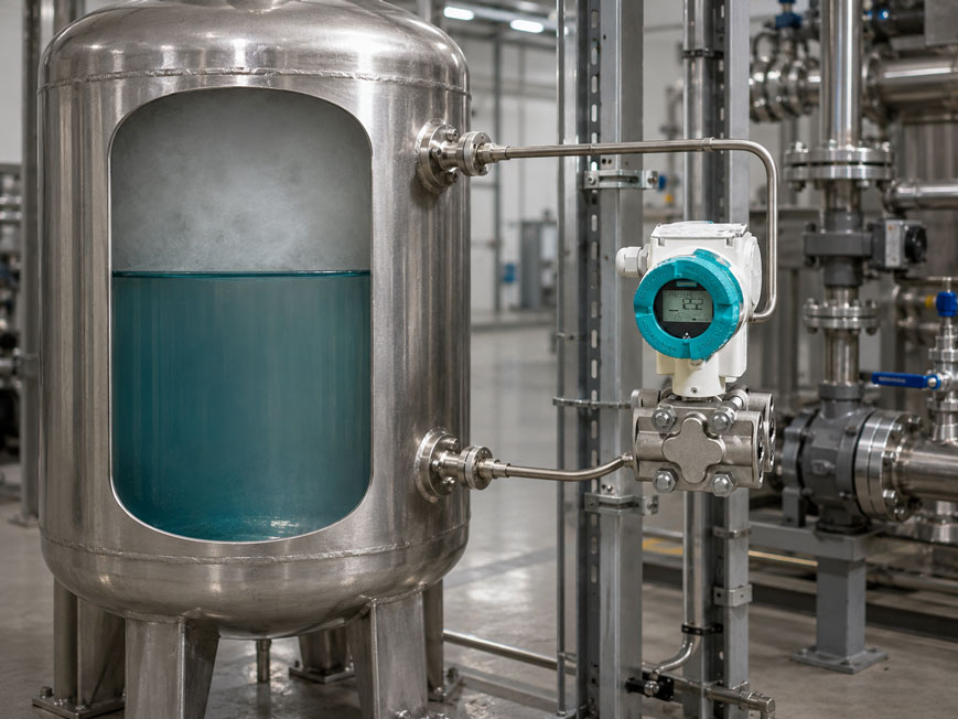
In a closed, pressurized tank, the level can only be determined reliably by hydrostatic measurement if the gas-space pressure acting on the liquid surface is subtracted from the measurement result or compensated directly.
In an open tank, measuring the hydrostatic pressure at the bottom of the tank is often sufficient. In a closed tank, however, the pressure of the gas or vapor space also acts on the liquid and therefore on the lower measuring connection.
A single gauge pressure transmitter at the bottom of the tank therefore cannot distinguish which part of its measured value is caused by the liquid level and which part is caused by the gas-space pressure.
The classic solution is a differential pressure transmitter. Its high-pressure side measures the pressure at the lower measuring point, while its low-pressure side is connected to the gas space. The gas-space pressure therefore acts on both sides of the measuring system and is largely compensated.
Ideally, only the hydrostatic pressure component of the liquid column remains as the level information. This turns a pressure measurement into a reliable level measurement – provided that density, connection positions, reference line and zero point are taken into account correctly.
A particularly suitable example from the ICS portfolio is the Siemens SITRANS P320. It is designed, among other applications, for differential pressure and level measurements in open and closed vessels. Another suitable solution is the WIKA DPT-20 differential pressure transmitter, which can also be used for hydrostatic level measurement in closed tanks.
For difficult, highly viscous, aggressive, hot or crystallizing media, diaphragm seal systems can also be used. Further solutions can be found under level measurement technology at ICS Schneider.
Table of Contents
- Why does a simple bottom-pressure measurement not work in a pressurized tank?
- Calculating hydrostatic pressure correctly
- How does the differential pressure transmitter compensate gas-space pressure?
- Calculation example for a pressurized tank
- Selecting the measuring range according to the liquid column rather than tank pressure
- Still considering static operating pressure
- Connecting the HP and LP sides correctly
- Dry reference line: Dry Leg
- Filled reference line: Wet Leg
- Why condensate in the reference line is problematic
- Level measurement with diaphragm seals and capillary lines
- Understanding zero elevation and zero suppression
- Considering the medium density correctly
- Temperature influence on density and the measuring system
- Considering the transmitter installation height
- When the density of the gas space also becomes relevant
- Manifold and commissioning
- Avoiding one-sided overload
- Scaling the 0% and 100% points correctly
- Converting level height into volume
- Why two separate pressure transmitters are not always the best alternative
- Practical example: level appears to change with tank pressure
- Typical fault patterns
- Recommended design and test procedure
- Suitable differential pressure technology from ICS Schneider
- Conclusion
- FAQ
Why does a simple bottom-pressure measurement not work in a pressurized tank?
In an open tank, essentially atmospheric pressure acts on the liquid surface.
If a gauge pressure transmitter is installed at the bottom of the tank, atmospheric pressure is compensated via the reference side of the sensor.
The measured pressure then approximately corresponds only to the hydrostatic pressure of the liquid column.
The situation is different in a closed pressurized tank
An additional gas-space pressure acts on the liquid surface.
The pressure at the lower measuring connection therefore consists of:
pbottom = pgas + ρ · g · h
where:
pbottom= pressure at the lower measuring connection,pgas= pressure in the gas space,ρ= density of the liquid,g= gravitational acceleration,h= liquid height above the lower measuring point.
A single pressure transmitter measures both components together
If, for example, the gas-space pressure increases while the level remains constant, the pressure measured at the bottom of the tank also increases.
A simple bottom-mounted pressure transmitter would incorrectly interpret this as a higher level.
In a pressurized vessel, the gas-space pressure must therefore either be measured separately or compensated directly using differential pressure measurement.
Calculating hydrostatic pressure correctly
The hydrostatic pressure of a liquid column is described by:
phyd = ρ · g · h
For water with a density of approximately:
1,000 kg/m³
the pressure per meter of liquid height is approximately:
98.1 mbar/m
Example
At a liquid height of:
2.5 m
the hydrostatic pressure for water is:
phyd ≈ 245 mbar
This hydrostatic pressure is comparatively small.
At the same time, the vessel may, for example, be under a gas-space pressure of:
5 bar
The level is then determined from a differential pressure of only about 245 mbar, even though both process connections are at a static pressure level of around 5 bar.
How does the differential pressure transmitter compensate gas-space pressure?
A differential pressure transmitter has two process sides:
- high-pressure side or HP side,
- low-pressure side or LP side.
For a classic level measurement on a closed tank, the HP side is connected to the lower tank connection and the LP side to the gas space.
The high-pressure side is exposed to
pHP = pgas + ρ · g · h
The low-pressure side is exposed to
pLP = pgas
The differential pressure transmitter calculates:
Δp = pHP - pLP
This gives:
Δp = pgas + ρ · g · h - pgas
and therefore:
Δp = ρ · g · h
The gas-space pressure cancels out mathematically.
As long as the same gas-space pressure is transmitted to both sides of the measuring system, the level indication remains independent of whether the tank is pressurized, for example, at 2 bar, 5 bar or 8 bar.
Calculation example for a pressurized tank
A closed process vessel contains a liquid with a density of:
800 kg/m³
The required level measuring range is:
0 … 2.5 m
The gas-space pressure can vary between:
2 … 6 bar
.
Hydrostatic pressure at 100% level
Δp = ρ · g · h
Δp = 800 kg/m³ · 9.81 m/s² · 2.5 m
Δp ≈ 19,620 Pa
or:
Δp ≈ 196 mbar
At 0%
with an ideal arrangement:
Δp = 0 mbar
At 100%
the result is:
Δp ≈ 196 mbar
The actual level measuring range is therefore only approximately:
0 … 196 mbar
even though a static pressure of several bar may simultaneously be applied to both sides of the differential pressure transmitter.
Selecting the measuring range according to the liquid column rather than tank pressure
A common design mistake is to select the differential pressure measuring range according to the maximum tank pressure.
For level measurement, however, the hydrostatic pressure difference is the primary factor.
Example
Tank pressure:
0 … 10 bar
Hydrostatic measuring span:
0 … 250 mbar
A differential pressure range of 10 bar is therefore not required for the actual measuring function.
An excessively large differential pressure range would reduce the usable resolution and often also worsen the measurement uncertainty for small level changes.
The transmitter should therefore be selected so that the actual hydrostatic span lies within a technically favorable range of the measuring cell.
Still considering static operating pressure
Although the differential pressure measuring range may be comparatively small, the transmitter must safely withstand the static process pressure applied to both sides.
A distinction must therefore be made between:
- differential pressure measuring range,
- permissible static operating pressure.
Example
A transmitter measures:
0 … 200 mbar differential pressure
but may be designed to withstand a static operating pressure of many bar or even several hundred bar.
These two values must not be confused when selecting the device.
Pressure peaks are particularly critical
In addition to normal tank pressure, the following should also be considered:
- filling and emptying processes,
- pressure surges,
- cleaning processes,
- valve switching,
- possible one-sided pressure loads.
Connecting the HP and LP sides correctly
For a classic level measurement in a closed tank, the following generally applies:
- HP side: lower measuring connection in the liquid region,
- LP side: upper connection in the gas space.
The lower connection
should be positioned so that it is reliably exposed to liquid throughout the intended measuring range.
The height difference between this measuring point and the required zero level must be taken into account during scaling.
The upper connection
transmits the gas-space pressure to the LP side.
The design of this reference side determines whether a dry or filled reference line should be used.
Dry reference line: Dry Leg
With a non-condensing gas, the line from the gas space to the LP side can be designed as a dry reference line.
In this case, the line mainly contains gas.
Ideally
the following applies approximately on the LP side:
pLP = pgas
The hydrostatic effect of the gas column is often small with short lines and low gas density.
Requirement
The line must actually remain dry.
With steam, humid gases or changing temperatures, condensate may form.
This changes the pressure column on the LP side and therefore also the zero point.
Filled reference line: Wet Leg
If condensation on the LP side cannot be reliably prevented, the reference line is often deliberately filled completely with a liquid.
This arrangement is referred to as a wet leg.
The liquid column creates an additional hydrostatic pressure
The LP side is then exposed to:
pLP = pgas + ρref · g · Href
For the transmitter, this results in:
Δp = ρprocess · g · h - ρref · g · Href
This can result in negative differential pressure when the tank is empty
This is not an error.
The constant liquid column in the wet-leg line produces a defined zero-point shift that must be taken into account during configuration.
A stable reference column is essential
The wet-leg line must be:
- completely filled,
- free of bubbles,
- as temperature-stable as possible,
- protected against uncontrolled evaporation or draining
.
Why condensate in the reference line is problematic
An undefined intermediate condition is particularly critical.
For example, a reference line originally designed as a dry leg may gradually begin to fill partially with condensate during operation.
This continuously changes the additional hydrostatic load on the LP side.
Typical fault pattern
The actual level remains constant, but the indication slowly drifts.
After extended shutdowns or temperature changes, the system shows different values than before.
The transmitter itself is not necessarily the cause
The differential pressure transmitter may be measuring the pressure difference supplied to it through the two lines completely correctly.
The problem is the non-reproducible reference column.
With condensing media, a deliberate decision must therefore be made between a reliably dry reference side and a defined, fully filled reference side.
Level measurement with diaphragm seals and capillary lines
Direct impulse lines may be unsuitable under difficult process conditions.
This applies, for example, to:
- highly viscous media,
- crystallizing liquids,
- aggressive media,
- high temperatures,
- hygienic applications,
- media prone to deposits.
In such applications, the differential pressure transmitter can be isolated from the process using diaphragm seals.
Pressure is transmitted hydraulically through a system fill fluid in the capillary lines.
Two diaphragm seals can be used on closed tanks
One diaphragm seal is installed at the lower liquid connection and a second at the upper gas-space connection.
Both are connected to the differential pressure transmitter via capillary lines.
However, this introduces additional influencing factors
- density of the system fill fluid,
- height differences,
- capillary length,
- temperature of the capillaries,
- temperature differences between the two sides.
These influences must already be considered during design and when calculating the lower and upper range values.
Capillary lines should be exposed to temperatures that are as similar as possible
Different heating of the two capillaries can lead to different volume and pressure changes in the system fill fluid.
With small differential pressure spans, this can have a significant effect on the indicated level.
Understanding zero elevation and zero suppression
In a real installation, 0% level does not automatically correspond to 0 mbar differential pressure.
Possible causes include:
- installation height of the transmitter,
- wet-leg reference column,
- capillary lines with diaphragm seals,
- lower measuring connection below the defined 0% level.
Example with a wet leg
The LP side is loaded by a constant liquid column.
With an empty tank, the transmitter may, for example, measure:
-300 mbar
and with a full tank:
-50 mbar
The actual measuring span is still:
250 mbar
The output can therefore be configured as:
-300 mbar = 4 mA = 0%
and:
-50 mbar = 20 mA = 100%
A negative differential pressure with an empty or partially filled tank is therefore technically completely plausible in such installations.
Considering the medium density correctly
Hydrostatic level measurement does not directly measure a geometric height.
It measures the pressure resulting from density and liquid height.
From:
Δp = ρ · g · h
follows:
h = Δp / (ρ · g)
If the density changes
the differential pressure also changes at the same geometric level.
Example
A liquid column of:
2 m
produces approximately:
196 mbar
at:
ρ = 1,000 kg/m³
.
At:
ρ = 800 kg/m³
it is only approximately:
157 mbar
If the evaluation continued to assume 1,000 kg/m³, the indicated level would be significantly incorrect.
This is particularly relevant for
- large temperature changes,
- changing products,
- different concentrations,
- liquefied gases,
- process media with strongly temperature-dependent density.
Temperature influence on density and the measuring system
Temperature can influence hydrostatic level measurement in several ways.
1. Density of the process medium
The liquid density changes with temperature and therefore so does the hydrostatic pressure per meter of level.
2. Density of a wet-leg liquid
The constant reference column can also be temperature-dependent.
3. Diaphragm seal system
With capillary lines, temperature changes can influence the system fill fluid.
4. Transmitter
The differential pressure transmitter itself also has temperature-dependent measurement deviations.
With very small hydrostatic measuring spans and large temperature changes, not only the accuracy of the transmitter should therefore be considered, but the complete installed measuring system.
Considering the transmitter installation height
In practice, the differential pressure transmitter is often not installed exactly at the height of the lower process connection.
This creates an additional liquid column between the process connection and the transmitter.
With a liquid-filled HP line
a vertical liquid column above the transmitter increases the pressure acting on the HP side.
This additional hydrostatic height changes the lower range value.
It is therefore not only the tank geometry that matters, but also:
- height of the lower process connection,
- height of the upper connection,
- installation height of the transmitter,
- fill condition of both lines.
After changing the installation height, the scaling should therefore be checked again.
When the density of the gas space also becomes relevant
In many applications, the hydrostatic effect of the gas column in a dry reference line is neglected.
This is often justified for short lines, moderate pressures and low gas density.
At high pressures, however, gas density can increase significantly
Together with large vertical height differences, this can create an additional hydrostatic pressure.
For high accuracy requirements, the following should therefore also be considered:
- gas type,
- gas pressure,
- gas temperature,
- vertical height of the reference line.
The effect is usually much smaller than with a liquid column, but it can become relevant for very small differential pressure spans.
Manifold and commissioning
Differential pressure transmitters are commonly installed in process plants with a three- or five-valve manifold.
This allows, among other things:
- isolation of the HP side,
- isolation of the LP side,
- equalization of both sides,
- venting or draining of measuring lines,
- connection of calibration or test equipment.
For zero adjustment
the equalizing valve can be used to apply the same pressure to both sides of the transmitter.
Under these defined conditions, the transmitter should indicate a differential pressure of:
0
provided that no additional hydrostatic columns act between the manifold and the measuring cell.
The valve sequence is important
Incorrect opening or closing can briefly create high one-sided differential pressures.
Commissioning should therefore always be carried out according to the operating instructions for the transmitter and manifold being used.
Avoiding one-sided overload
During normal operation, the HP and LP sides are often at nearly the same static pressure level.
During maintenance or commissioning, however, one side may be depressurized while the other side is exposed to the full tank pressure.
Example
LP valve closed or line vented:
0 bar
HP side:
8 bar
The transmitter then experiences not the normal level differential of a few hundred mbar, but a significant one-sided pressure load.
When selecting the device, the following must therefore be checked:
- permissible static pressure,
- permissible one-sided overload,
- permissible differential pressure overload.
Scaling the 0% and 100% points correctly
For configuration, the actual differential pressures occurring at the transmitter for the lower and upper levels must be determined.
With an ideal dry-leg arrangement
the following may apply, for example:
0% = 0 mbar
100% = 300 mbar
With a wet-leg or diaphragm-seal arrangement
the following may instead apply:
0% = -420 mbar
100% = -120 mbar
In both cases, the measuring span is:
300 mbar
The current output can be scaled accordingly to:
4 … 20 mA
.
For configuration, the lower and upper range values are therefore decisive – not the assumption that an empty tank must necessarily produce 0 mbar differential pressure.
Converting level height into volume
The differential pressure transmitter initially determines a hydrostatic level height.
This is directly proportional to volume only for a vessel with a constant horizontal cross-section.
For a vertical cylindrical tank
the following applies approximately:
50% level height = 50% volume
For other tank shapes
the relationship is not linear.
Examples include:
- horizontal cylindrical tanks,
- spherical tanks,
- conical vessels,
- vessels with dished bottoms.
For correct volume indication, a tank characteristic curve or linearization is then required in the:
- transmitter,
- PLC,
- control system.
Why two separate pressure transmitters are not always the best alternative
In principle, the pressure at the bottom of the tank and the gas-space pressure could also be measured with two separate pressure transmitters and then subtracted from one another in the control system.
This can be useful in certain installations.
However, a small hydrostatic difference at high tank pressure creates a demanding measurement task
For example:
pbottom = 10.20 bar
and:
ptop = 10.00 bar
Only the difference is required:
0.20 bar
With two separate measuring instruments, the measurement deviations of both pressure measurements contribute to the calculated difference.
A differential pressure transmitter, on the other hand, directly measures the small pressure difference while simultaneously operating at a high static pressure.
For classic hydrostatic level applications in pressurized vessels, this is often the more favorable metrological solution.
Practical example: level appears to change with tank pressure
In a closed process vessel, the level is measured using a differential pressure transmitter.
During the production process, the gas-space pressure increases from:
2 bar
to:
4 bar
.
The actual liquid level remains unchanged.
Fault pattern
The level indication nevertheless changes by several percent.
Initial assumption
The differential pressure transmitter is pressure-dependent or defective.
Inspection
The HP side is correctly connected to the lower tank connection.
On the LP side, however, there is a long reference line that was originally designed as a dry leg.
During operation, condensate has partially accumulated in it.
Result
As process pressure increases and temperatures change, the condition of the condensate column changes.
The LP pressure therefore no longer reproducibly corresponds to the pure gas-space pressure.
Solution
The reference side is redesigned for the actual process conditions.
Depending on the medium, for example, the following can be used:
- a reliably dry reference line,
- a defined wet-leg arrangement,
- a diaphragm seal system.
After correct zero and span configuration, the level indication remains stable when the gas-space pressure changes.
The example shows that the differential pressure measuring cell is only one part of the measuring system. In closed vessels, the LP side in particular plays a decisive role in whether the gas-space pressure is actually compensated correctly.
Typical fault patterns
| Observation | Possible cause | Recommended check |
|---|---|---|
| Level increases with gas-space pressure | Gas-space pressure is not compensated or is compensated incorrectly | Check LP connection and reference line |
| Level slowly drifts | Condensation in a dry-leg line | Check the condition of the reference line |
| Indication has a constant offset | Installation height or liquid column not taken into account | Recalculate lower range value |
| Empty tank shows negative differential pressure | Wet leg or capillary system creates a constant opposing pressure | Check whether the zero-point shift is intended by design |
| Indication changes with ambient temperature | Density change or unequal capillary influence | Check process and capillary temperatures |
| Measured value incorrect after product change | Different medium density | Check density value and scaling |
| Measured value jumps after valve operation | Incorrect valve sequence or air/gas bubbles | Check manifold and venting |
| Zero adjustment not reproducible | Unequal pressures or unstable liquid columns | Check equalizing valve and impulse lines |
| Transmitter shows a significantly different value after maintenance | Line filled differently or installation height changed | Recheck HP/LP lines and heights |
| Level is correct only at one temperature | Density compensation missing | Consider density-temperature relationship |
| Measurement is correct at the bottom but not at the top | Incorrect density or incorrect measuring span | Check 0% and 100% points |
| Measurement is correct with test pressure but not in the process | Process lines or diaphragm seals create additional pressure | Evaluate the complete installed measuring system |
| Transmitter is overloaded during commissioning | One-sided exposure to full tank pressure | Check valve sequence and overload limits |
Recommended design and test procedure
- Define the tank type: Clearly account for a closed or pressurized vessel.
- Determine the 0% and 100% levels: Define the actual required liquid height.
- Determine the medium density: Use the density over the relevant temperature range.
- Calculate the hydrostatic measuring span: Apply Δp = ρ · g · h.
- Determine the gas-space pressure: Record minimum, normal and maximum operating pressure.
- Check the static pressure range: Size the differential pressure transmitter accordingly.
- Consider one-sided overload: Include maintenance and valve-switching conditions.
- Define the lower measuring connection: Document its height relative to the 0% level.
- Define the upper connection: Reliably measure the gas-space pressure.
- Select the reference concept: Define dry leg, wet leg or diaphragm seal system.
- Check condensation behavior: Avoid undefined liquid columns.
- Define the transmitter installation height: Take additional hydrostatic columns into account.
- Design diaphragm seals if required: Match material, capillary length and fill fluid.
- Evaluate capillaries thermally: Provide temperature conditions that are as similar as possible.
- Calculate LRV: Determine differential pressure at 0%.
- Calculate URV: Determine differential pressure at 100%.
- Scale the output: For example, 4 mA = 0% and 20 mA = 100%.
- Install the manifold correctly: Consider isolation, equalization and test connections.
- Vent or fill the impulse lines: Establish a defined operating condition.
- Check the zero point: After actual installation and under defined pressure conditions.
- Verify several levels: If possible, using an independent reference.
- Change the gas-space pressure: Check whether the level indication remains stable.
- Evaluate temperature behavior: Particularly for high accuracy requirements.
- Document the results: Record density, heights, LRV, URV, line condition and configuration.
Suitable differential pressure technology from ICS Schneider
Siemens SITRANS P320
The Siemens SITRANS P320 is a process transmitter for gauge pressure, absolute pressure, differential pressure, flow and level.
Features particularly relevant to the application described here include:
- differential pressure measurement even at high static process pressure,
- level measurement in open and closed vessels,
- small differential pressure measuring ranges,
- 4–20 mA/HART communication,
- extensive diagnostic functions,
- optional diaphragm seal systems for special process conditions.
The P320 is therefore a particularly suitable solution when the gas-space pressure of a closed tank is to be compensated directly via the LP side.
WIKA DPT-20
The WIKA DPT-20 is also specifically designed for industrial differential pressure measurements.
Typical applications include:
- level measurement in open and closed tanks,
- flow measurement,
- filter monitoring,
- pump monitoring.
The DPT-20 offers freely scalable differential pressure ranges and can be combined with diaphragm seals when the process medium should not be routed directly to the transmitter.
IDPT200 differential pressure transmitter
The IDPT200 is designed for differential pressure measurements in the process industry.
Its typical applications explicitly include:
level measurement on closed, pressurized vessels
.
Depending on the application, different diaphragm seals can be fitted to adapt the measuring system to difficult process media.
WIKA diaphragm seal model 990.27
The WIKA 990.27 features a flange connection with a flush diaphragm and can be combined with suitable pressure measuring instruments by direct mounting or capillary connection.
Such diaphragm seal systems are particularly useful for:
- adhesive media,
- highly viscous liquids,
- high process temperatures,
- aggressive media,
- applications in which impulse lines would be problematic.
Further devices can be found under process transmitters and differential pressure transmitters and under level measurement technology at ICS Schneider.
Conclusion
Hydrostatic level measurement in a closed pressurized tank is technically reliable when the pressure difference between the liquid side and the gas space is evaluated rather than the absolute bottom pressure.
The gas-space pressure must be compensated
A single pressure transmitter at the bottom of the tank cannot distinguish between level and gas-space pressure.
The differential pressure transmitter performs the compensation directly
The gas-space pressure acts on the HP and LP sides and therefore largely cancels out in the differential signal.
The hydrostatic span determines the actual measuring range
A tank may be pressurized at several bar while the differential pressure to be measured is only a few hundred mbar.
Static operating pressure still remains crucial
The measuring cell and process connections must safely withstand the maximum tank pressure that can occur.
The LP side is particularly important
Dry leg, wet leg, condensate and diaphragm seal systems create different zero-point conditions.
0% does not have to mean 0 mbar
Reference columns, installation height and capillary lines can produce positive or negative zero-point shifts.
Density is part of the measurement equation
If the liquid density changes, the hydrostatic differential pressure also changes at the same level.
The complete measuring arrangement must be considered
Transmitter, impulse lines, diaphragm seals, manifold, installation height, medium and temperature together form the measuring system.
For practical applications
Determine the level span → record the medium density → calculate the hydrostatic differential pressure → check the maximum static tank pressure → connect the HP side at the bottom and the LP side to the gas space → deliberately select dry leg, wet leg or diaphragm seal system → consider installation heights and reference columns → calculate lower and upper range values → operate the manifold correctly → check the zero point under actual installation conditions → verify the level at several points → confirm that changes in gas-space pressure do not influence the indicated level.
FAQ: Measuring Level Correctly in a Pressurized Tank
How do you measure the level in a closed pressurized tank?
Typically with a differential pressure transmitter. The HP side is connected to the lower liquid connection and the LP side to the gas space.
Why is a pressure transmitter at the bottom of the tank not sufficient?
Because it measures both the hydrostatic liquid pressure and the gas-space pressure acting on the liquid surface.
How is the gas-space pressure compensated?
The gas-space pressure is routed to the LP side of the differential pressure transmitter. Since the same pressure is also present on the liquid side, it largely cancels out in the differential measurement.
Which formula applies to hydrostatic level?
Hydrostatic pressure is calculated using Δp = ρ · g · h.
What does HP mean on a differential pressure transmitter?
HP stands for High Pressure. In a classic level measurement, this side is connected to the lower tank connection.
What does LP mean?
LP stands for Low Pressure. In a closed tank, this side is typically connected to the gas space.
Does the differential pressure measuring range have to correspond to the maximum tank pressure?
No. The actual measuring range is determined by the hydrostatic pressure span. However, the transmitter must also be suitable for the maximum static tank pressure.
What is static pressure in a differential pressure transmitter?
It is the pressure applied simultaneously to both process sides. It can be considerably higher than the differential pressure actually being measured.
What is a dry leg?
A dry leg is a dry reference line from the gas space to the LP side of the differential pressure transmitter.
When is a dry leg suitable?
When the gas does not condense and the reference line reliably remains dry.
What happens if condensate accumulates in a dry leg?
The liquid column creates additional hydrostatic pressure on the LP side and therefore shifts the indicated level.
What is a wet leg?
A wet leg is a reference line on the LP side that is deliberately filled completely with liquid.
Why is a wet leg used?
If condensation cannot be prevented, a reproducible reference pressure can be created using a defined filled line.
Why can an empty tank produce negative differential pressure?
A wet-leg column or diaphragm seal system can create a constant additional pressure on the LP side. This can result in negative differential pressure at 0% level.
Is negative differential pressure during level measurement an error?
No. The important point is that the lower and upper range values are calculated correctly and scaled accordingly in the transmitter.
What do zero elevation and zero suppression mean?
They account for the fact that, due to the installation, the differential pressure at 0% level does not necessarily equal 0 mbar.
Why does density influence level measurement?
Hydrostatic pressure is proportional to liquid density. At the same height, a denser liquid produces a higher pressure.
Does temperature have to be considered?
Yes. It can influence the density of the process medium, the wet-leg liquid and diaphragm seal systems.
When should diaphragm seals be used?
For highly viscous, aggressive, hot, crystallizing or hygienically demanding media, diaphragm seals can offer advantages over direct impulse lines.
How do diaphragm seals work?
A diaphragm separates the process medium from the measuring instrument. The process pressure is transmitted hydraulically to the transmitter via a system fill fluid.
Why are capillary lengths important with diaphragm seals?
The length, height and temperature of the capillaries influence the behavior of the system fill fluid and can therefore affect the zero point and measurement accuracy.
Should both capillaries be the same length?
With symmetrical differential pressure diaphragm seal systems, comparable capillary lengths and temperature conditions that are as similar as possible are generally advantageous because thermal influences then act more similarly on both sides.
Why is a manifold used?
It enables controlled isolation of both process sides, pressure equalization, and testing, venting and maintenance work.
Can a differential pressure transmitter be overloaded during commissioning?
Yes. If one side is exposed to full process pressure while the other side is depressurized, a very high one-sided differential pressure can occur temporarily.
How is a differential pressure transmitter zeroed?
Typically, both measuring sides are brought to the same pressure via the manifold, after which the zero point is checked or adjusted according to the manufacturer’s instructions.
Can two pressure transmitters be used instead of one differential pressure transmitter?
In principle, yes. However, with small hydrostatic differences at a high static pressure level, subtracting two separate pressure measurements may result in greater overall measurement uncertainty.
Can tank volume be determined directly from differential pressure?
Only for vessels with a correspondingly linear relationship between level height and volume. Other tank shapes require tank linearization.
Which Siemens transmitter is suitable for this application?
The Siemens SITRANS P320 is designed, among other applications, for differential pressure and level measurements in closed vessels.
Which WIKA transmitter is suitable?
The WIKA DPT-20 is suitable for level measurements in open and closed tanks and can be combined with diaphragm seals for difficult media.
Does ICS offer other differential pressure transmitters for pressurized vessels?
Yes. The IDPT200 is also designed for level measurements on closed, pressurized vessels.
Where can I find further level measurement technology?
Further solutions can be found under level measurement technology at ICS Schneider.