


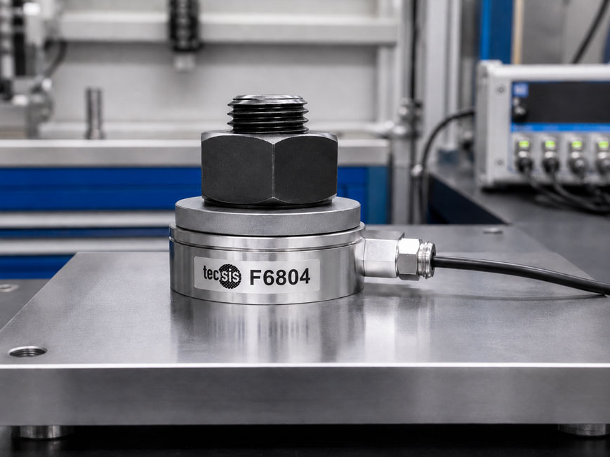
A ring load cell can directly measure the actual preload force of a bolted joint when the bolt force is transmitted through the sensor concentrically, axially and without disturbing transverse forces or bending moments.
This differs significantly from conventional assembly based on a specified tightening torque. Torque is only an indirect quantity, and its relationship to the resulting preload force is strongly influenced by friction in the thread and at the bearing surfaces.
A ring load cell, on the other hand, is installed directly in the force flow of the bolted joint and effectively acts as a measuring washer.
The following factors are particularly important for reliable measurement results:
- suitable measuring range,
- concentric bolt guidance,
- parallel and sufficiently hard bearing surfaces,
- uniform force application across the ring surface,
- avoidance of transverse forces and tilting moments,
- reproducible mounting position,
- suitable signal amplification and calibration.
The accuracy of a preload force measurement is therefore not determined by the load cell alone. Even an inclined bearing surface, an excessively soft washer or an off-centre bolt can alter the force application and significantly affect the measurement result.
A particularly suitable product from the ICS portfolio is the WIKA F6804 ring load cell. It was specifically developed for bolt force and preload measurements and is available for nominal forces from 3 kN to 450 kN.
Further solutions can be found under ring load cells and under force, weighing, speed and torque sensors at ICS Schneider.
Table of Contents
- How does a ring load cell measure bolt preload?
- What is bolt preload force?
- Why is tightening torque not sufficient as a force measurement?
- Installing a ring load cell correctly in the force flow
- Why concentric force application is crucial
- How do transverse forces and tilting moments occur?
- Preparing bearing surfaces correctly
- Load distribution using washers and pressure pieces
- Selecting the correct inner diameter and bolt diameter
- Selecting the correct measuring range
- Monitoring the measured value during assembly
- Evaluating the mV/V signal correctly
- Considering calibration and mounting position
- Influence of the sensor on the bolted joint
- Distinguishing static and dynamic bolt forces
- Considering temperature influences
- Practical example: checking the preload force of a bolted joint
- Typical fault patterns
- Recommended measurement and assembly procedure
- Suitable ring load cells from ICS Schneider
- Conclusion
- FAQ
How does a ring load cell measure bolt preload?
A ring load cell is a compression force transducer with a central through-hole.
The bolt or threaded rod is passed through this hole while the sensor is positioned between two load-transmitting surfaces.
When the bolt is tightened, this generates:
- a tensile force in the bolt,
- a corresponding compressive force in the clamped components.
The ring load cell is located within this compressive force path and measures the force transmitted through it.
Under static equilibrium
the measured compressive force essentially corresponds to the preload force of the bolt, provided that the complete force flow passes through the sensor and no additional parallel force paths are present.
The F6804 is specifically designed for this application and can therefore be used as a:
measuring washer
.
What is bolt preload force?
When a bolt is tightened, it is elastically elongated.
At the same time, the clamped components are compressed.
The resulting internal force is referred to as preload force.
It is important, among other things, for:
- secure frictional connection,
- tightness of flange connections,
- prevention of relative movement,
- fatigue strength of the bolt,
- reproducible assembly processes.
Insufficient preload force
can lead, for example, to:
- loosening,
- joint separation,
- leakage,
- alternating bolt loads
.
Excessive preload force
can, on the other hand:
- overload the bolt or thread,
- plastically deform components,
- damage seals,
- overload the load cell.
Direct force measurement is therefore particularly useful for test benches, development tasks and critical assembly processes.
Why is tightening torque not sufficient as a force measurement?
Many bolted joints are assembled using a specified tightening torque.
However, only part of the tightening torque is converted into bolt elongation and therefore into preload force.
A large proportion is required to overcome friction.
Relevant factors include:
- thread friction,
- friction under the bolt head or nut bearing surface,
- lubrication condition,
- surface coating,
- material pairing,
- surface roughness.
The same torque therefore does not automatically produce the same preload force
For example, if two identical bolts are tightened to the same torque but one connection is lubricated and the other is dry, different preload forces can result.
The ring load cell, on the other hand, directly measures the resulting mechanical force.
For development and testing tasks, direct preload force measurement is therefore particularly useful for investigating the actual relationship between torque, friction conditions and bolt force.
Installing a ring load cell correctly in the force flow
The sensor must be installed so that the entire relevant bolt force passes through its measuring structure.
A typical arrangement consists of:
bolt head or nut → load distribution → ring load cell → bearing surface
The bolt passes through the central hole of the sensor.
A closed axial force path is essential
The force must not bypass the sensor partially through:
- adjacent spacers,
- lateral stops,
- housing components,
- additional parallel bearing surfaces.
Otherwise, the load cell will measure only part of the actual preload force.
Why concentric force application is crucial
For the WIKA F6804, the manufacturer explicitly specifies that the measuring force must be applied concentrically and without transverse forces.
The resulting compressive force should pass as symmetrically as possible through the ring geometry.
With ideal installation
the bolt axis is positioned as concentrically as possible relative to the centre axis of the load cell.
The load is distributed uniformly across the intended ring surface.
With off-centre loading
the measuring body is deformed asymmetrically.
The sensor then no longer responds exclusively to the desired axial compressive force.
Possible consequences include:
- measurement deviation,
- poorer repeatability,
- different results after reinstallation,
- mechanical overloading of individual areas.
How do transverse forces and tilting moments occur?
Transverse forces occur when the resulting force is not exactly parallel to the sensor axis.
Typical causes include:
- an inclined bolt,
- non-parallel bearing surfaces,
- a laterally displaced nut,
- a deformed pressure washer,
- one-sided component support,
- lateral loading during assembly.
Tilting moment due to an inclined bearing surface
If one side of the load cell is loaded before the opposite side, eccentric force application occurs.
This additionally bends the ring.
This type of loading should be avoided.
The tightening process itself can also generate transverse forces
When a nut or bolt is rotated, frictional forces occur at the bearing surface.
The mechanical design must therefore ensure that no impermissible torsional or transverse load is transmitted into the sensor as a result.
Preparing bearing surfaces correctly
For the F6804, WIKA specifies a flat and sufficiently hard bearing surface.
The reason is the very compact sensor geometry.
A soft or uneven surface can deform differently under load and therefore alter the force distribution across the ring.
Suitable bearing surfaces should be
- flat,
- clean,
- free of burrs,
- sufficiently rigid,
- sufficiently hard
.
Potentially problematic conditions include
- paint residues,
- weld spatter,
- damage,
- soft plastic intermediate layers,
- point contacts.
The quality of the mechanical bearing surface is part of the measuring chain and not merely an installation issue.
Load distribution using washers and pressure pieces
Depending on the bolt and sensor geometry, sufficiently rigid load distribution between the nut or bolt head and the load cell may be required.
The purpose of such an intermediate component is to distribute the bolt force as evenly as possible across the intended ring surface.
A washer that is too thin or too soft can bend
This concentrates the load more strongly near the bolt and prevents uniform distribution across the sensor.
At high forces, it should therefore be checked whether the following are required:
- a hardened washer,
- a ground pressure piece,
- a specially designed load distribution plate.
The actual design must match the geometry and the manufacturer’s specifications for the load cell being used.
Selecting the correct inner diameter and bolt diameter
The through-hole of the ring load cell must match the bolt or threaded rod being used.
Too little clearance
can cause the bolt to make lateral contact with the sensor.
This can generate transverse forces or additional force paths.
Too much clearance
makes installation easier, but increases the risk of off-centre positioning.
The mechanical design should therefore provide reproducible centring without laterally supporting the bolt against the sensor body.
Selecting the correct measuring range
The measuring range should match the maximum preload force actually expected.
The WIKA F6804 is available with nominal forces of:
3, 5, 10, 20, 50, 100, 150, 200, 300 and 450 kN
.
An excessively large measuring range
reduces the usable signal change for small bolt forces.
An excessively small measuring range
creates a risk of overload during tightening.
The limiting force specified for the F6804 is:
150% Fnom
.
The breaking force is:
200% Fnom
.
However, these limits are not normal operating ranges. The intended bolt preload force should remain within the specified nominal measuring range.
Monitoring the measured value during assembly
In bolted joints, the force can increase very quickly during tightening.
WIKA therefore explicitly recommends electrically connecting the load cell and monitoring the measured value during assembly.
This offers two advantages
- the desired preload force can be observed directly,
- accidental overloading of the sensor can be detected earlier.
During an assembly test, the bolt should therefore not first be fully tightened and the measuring instrument only connected afterwards.
The force measurement should already be operational before the actual tightening process begins.
Evaluating the mV/V signal correctly
The F6804 operates with a strain-gauge-based bridge signal.
The nominal rated output is:
1.0 ±10% mV/V
with a recommended excitation voltage of:
5 V DC
and a maximum of:
10 V DC
Example
With a bridge excitation of 5 V, a rated output of 1 mV/V produces approximately:
5 mV output signal
at nominal force.
This is a very small measuring signal.
For practical evaluation, a suitable:
- strain-gauge amplifier,
- weighing indicator,
- data acquisition input
is therefore required.
Important for wiring
With millivolt signals, interference and voltage drops can play a greater role than with already amplified industrial signals.
The following are therefore particularly important:
- suitable shielded measuring cables,
- clean plug or terminal connections,
- separation from interference-generating power cables.
Considering calibration and mounting position
A ring load cell can be sensitive to the specific mechanical installation situation.
For the F6804, WIKA explicitly points out that the compact geometry is sensitive to changed or different mounting conditions.
For an unchanged mounting position, the datasheet specifies a relative range of:
0.5% Fnom
.
For reproducible measurements, this means
the mechanical installation conditions should remain as constant as possible.
If, for example, the following are changed between two measurements:
- bearing plate,
- load distribution washer,
- bolt position,
- tightening side,
- mounting orientation,
- contact surfaces,
the measurement result may also change.
For high accuracy requirements, calibration or verification should therefore reproduce the actual mechanical installation conditions as closely as possible.
Influence of the sensor on the bolted joint
Installing a ring load cell changes the geometry and stiffness of the original bolted joint.
The sensor has a defined installation height and elastic deformation.
This can change
- the bolt grip length,
- the stiffness ratio between the bolt and the clamped components,
- settling behaviour,
- the required bolt length.
This is particularly important if the ring load cell is only temporarily installed to investigate an existing production bolted joint.
The connection measured with the sensor is not necessarily mechanically identical to the later connection without the sensor.
For development tests
it should therefore be checked whether:
- the sensor is permanently part of the design,
- a dedicated measuring joint is used,
- the influence of the additional installation height must be taken into account.
Distinguishing static and dynamic bolt forces
The F6804 is particularly suitable for determining bolt forces and preload forces.
In a purely static measurement, for example, the preload force is determined immediately after tightening.
During actual operation, additional effects may occur
- changing operating forces,
- vibrations,
- thermal expansion,
- settling effects,
- relaxation.
As a result, the measured bolt force may change during operation.
For long-term investigations, not only the load cell but also the data acquisition system used must therefore be suitable for the required time resolution.
Considering temperature influences
A strain-gauge load cell also has temperature-dependent characteristics.
For the F6804, the nominal temperature range is specified as:
-10 … +60 °C
.
The operating temperature range is:
-20 … +80 °C
.
The temperature influence on the zero signal and rated output is specified as:
0.05% Fnom / 10 °C
in each case.
During temperature tests
the sensor and bolted joint should therefore be allowed to reach sufficient thermal stability.
In addition, temperature itself can change the bolt preload if the bolt and clamped components have different coefficients of thermal expansion.
A change in the measured force value due to temperature therefore does not necessarily originate solely from the sensor, but may represent an actual change in bolt force.
Practical example: checking the preload force of a bolted joint
A test bench is used to investigate which preload force is actually achieved at a specified tightening torque.
Test setup
- bolt passing through the central hole of the ring load cell,
- flat and sufficiently hard counter surface,
- rigid load distribution between nut and sensor,
- sensor concentric with the bolt axis,
- strain-gauge amplifier connected before tightening.
Target preload force
40 kN
For the application, an F6804 version with a suitable nominal measuring range above the maximum expected bolt force is selected.
First test
The bolt is tightened to the specified torque.
Measured preload force:
36 kN
Second test with the same bolt and the same torque
After changing the lubrication condition, the measured force is:
43 kN
The example clearly shows that the same torque does not necessarily produce the same preload force.
Additional repeatability test
If the force values fluctuate significantly despite an identical assembly process, the sensor should not immediately be assumed to be the cause.
The following should be checked in particular:
- friction conditions,
- bearing surfaces,
- centring,
- bolt quality,
- settling behaviour,
- repeatability of the mounting position.
Typical fault patterns
| Observation | Possible cause | Recommended check |
|---|---|---|
| Measured value changes significantly after reinstallation | different mounting position or force distribution | compare bearing surfaces and centring |
| Measured value increases when the bolt is moved sideways | transverse load or contact with sensor bore | check bolt guidance and radial clearance |
| Different values despite supposedly identical preload | eccentric force application | re-centre sensor and load distribution |
| Zero point changes after installation | mechanical preload or tilted bearing surface | unload sensor and inspect mounting surfaces |
| Sensor suddenly indicates very high force during tightening | measuring range too small or load peak | stop assembly and check nominal force |
| Measured value drifts after tightening | joint settling or creep | observe force over a defined period |
| Signal is very noisy | mV/V signal affected by EMC interference | check shielding and cable routing |
| Sensor reacts to rotation of the nut | torsion or frictional torque is being introduced | check load distribution and assembly concept |
| Values change with temperature | sensor effect and/or actual change in bolt force | record temperature and thermally stabilise the system |
| Force is significantly lower than expected from torque | friction or parallel force path | check bolting process and force flow |
| Ring shows visible one-sided pressure marks | uneven bearing surface | replace or rework bearing surface and pressure piece |
Recommended measurement and assembly procedure
- Determine maximum preload force: Consider the expected force range and possible assembly peaks.
- Select a suitable nominal measuring range: Do not oversize the sensor unnecessarily, but allow sufficient overload reserve.
- Check the inner diameter: The bolt must pass freely through the sensor without lateral contact.
- Check bearing surfaces: Ensure flatness, hardness, cleanliness and absence of burrs.
- Define load distribution: Use a sufficiently rigid washer or suitable pressure piece.
- Centre the sensor: Guide the bolt axis as concentrically as possible through the centre of the ring.
- Avoid transverse forces: Exclude inclined and lateral loads.
- Connect the measuring amplifier: Make the sensor electrically operational before tightening.
- Check the zero point: Zero correctly before loading or document the initial output signal.
- Tighten the bolt in a controlled manner: Monitor the force throughout the complete assembly process.
- Do not exceed nominal force: Stop assembly immediately if an unusual force increase occurs.
- Document the final value: Record the preload force immediately after tightening.
- Observe settling behaviour: If necessary, measure the force again after a defined waiting period.
- Repeat the assembly: Check repeatability over several tightening cycles.
- Document temperature: Particularly for comparative precision measurements.
- Keep installation conditions constant: Do not change bearing surfaces, centring or force path between measurements.
- Evaluate the results: Consider preload force, torque and, where applicable, friction or process parameters together.
Suitable ring load cells from ICS Schneider
WIKA F6804 – specifically for bolt forces and preload forces
The WIKA F6804 is designed for compression force measurement and specifically for bolt force and preload force measurements.
Its key technical specifications include:
- Nominal forces: 3 … 450 kN,
- relative linearity deviation: 2% Fnom,
- rated output: 1.0 ±10% mV/V,
- limiting force: 150% Fnom,
- breaking force: 200% Fnom,
- measuring body: stainless steel,
- degree of protection: IP65,
- nominal temperature range: -10 … +60 °C.
Particularly relevant for bolted joints is the manufacturer’s specification that the measuring force must be applied:
concentrically and without transverse forces
.
Flat and sufficiently hard bearing surfaces are also required.
WIKA F6212 – low-profile ring load cell up to 100 kN
If a particularly low installation height or larger inner diameter is required, the WIKA F6212 may also be of interest.
The series offers:
- nominal forces from 2 kN to 100 kN,
- low-profile design,
- compression force measurement,
- stainless-steel measuring body,
- IP65 degree of protection.
The F6212 is particularly intended for general static force measurements with ring geometry as well as spindle and press applications.
For direct determination of bolt preload forces, however, the F6804 is the particularly suitable product choice because WIKA specifically specifies this sensor for bolt forces and for use as a measuring washer.
Further versions can be found under ring load cells at ICS Schneider.
Conclusion
Ring load cells enable direct and highly transparent measurement of the actual bolt preload force and are therefore particularly suitable for development, test benches and assembly investigations.
The force must be applied axially
The bolt axis and sensor centre should be as concentric as possible.
Transverse forces and tilting moments distort the measurement
Inclined bearing surfaces, lateral bolt contact or uneven load distribution must be avoided.
The bearing surfaces are part of the measuring chain
They must be flat, sufficiently hard and mechanically stable.
The load must be distributed uniformly
Washers that are too soft or that bend under load can cause uneven loading of the ring surface.
The measuring range must match the bolt force
A sensor with too small a range can be overloaded during tightening, while an unnecessarily large measuring range reduces the usable signal resolution.
The sensor should already be monitored during tightening
This makes it possible both to set the desired preload force and to detect overload early.
The installation conditions must remain reproducible
With compact ring load cells, changes in mechanical installation can influence the measurement result.
For practical applications
Determine maximum bolt force → select a suitable measuring range → align bolt and sensor concentrically → provide flat and hard bearing surfaces → ensure sufficiently rigid load distribution → avoid transverse forces and tilting moments → connect the measuring amplifier before tightening → check the zero point → monitor preload force during assembly → record settling behaviour → keep the installation conditions unchanged for comparative measurements.
FAQ: Using Ring Load Cells Correctly for Bolt Preload
What is a ring load cell?
A ring load cell is a force sensor with a central through-hole that can measure compressive forces directly within the force flow.
Can it be used to measure the preload force of a bolt?
Yes. A ring load cell specifically designed for this purpose can be installed in the bolted joint like a measuring washer.
Which WIKA sensor is specifically suitable for bolt preload measurements?
The WIKA F6804 is specifically designed for bolt force and preload force measurements.
How is the ring load cell installed?
The bolt is passed through the central hole and the sensor is installed within the axial force path between suitable bearing surfaces.
Why must the bolt pass concentrically through the sensor?
An off-centre position causes uneven loading of the ring geometry and can therefore influence the measured value.
What does transverse-force-free force application mean?
The measuring force should act exclusively axially through the load cell. Lateral forces and tilting moments should be avoided.
What causes transverse forces?
Typical causes include inclined bolts, uneven bearing surfaces, lateral contact between the bolt and sensor housing or eccentrically loaded pressure pieces.
Why must the bearing surfaces be hard?
Soft surfaces can deform under load and thereby change the force distribution on the sensor.
Why must the bearing surfaces be flat?
An uneven surface initially loads only part of the ring and therefore creates eccentric force application or bending stress.
Do I need additional washers?
That depends on the design. The decisive factor is sufficiently rigid and uniform force distribution across the intended ring surface.
Can a normal thin washer cause problems?
Yes. If it bends significantly under high bolt force, the force may be applied unevenly to the sensor.
Is tightening torque the same as bolt preload force?
No. Tightening torque is strongly influenced by friction in the thread and beneath the bolt head or nut.
Why is direct force measurement better for testing?
It measures the actual resulting preload force and therefore enables direct evaluation of the assembly process.
Which measuring ranges are available for the WIKA F6804?
The F6804 is available with nominal forces from 3 kN to 450 kN.
What linearity deviation does the F6804 have?
A relative linearity deviation of 2% of nominal force is specified for the F6804.
What output signal does the F6804 provide?
The rated output is 1.0 ±10% mV/V.
Does the F6804 require a measuring amplifier?
For practical evaluation of the very small mV/V bridge signal, a suitable strain-gauge amplifier or corresponding data acquisition system is generally used.
What excitation voltage does the F6804 require?
The datasheet specifies an excitation voltage of 5 V DC, with a maximum of 10 V DC.
Can I connect the sensor only after tightening?
Measurement after tightening is technically possible, but WIKA recommends connecting the sensor and monitoring the measured value during assembly in order to avoid overload.
How much can the F6804 be overloaded?
A limiting force of 150% of nominal force is specified. However, this is not a normal operating range.
Can excessive preload force damage the sensor?
Yes. A suitable nominal measuring range should therefore be selected and the measured force monitored during tightening.
Can the mounting position influence the measured value?
Yes. WIKA explicitly points out that the compact geometry of the F6804 is sensitive to different or changed installation conditions.
Why does the bolt force continue to change after tightening?
Settling processes, relaxation, temperature changes and mechanical adaptation of the contact surfaces can subsequently change the preload force.
Can the load cell remain permanently in the bolted joint?
This is fundamentally a design question. Installation height, measuring range, environmental conditions, cable protection and the influence of the sensor on the joint must all be taken into account.
Does the ring load cell change the bolted joint?
Yes. Its additional installation height and stiffness can affect the grip length and the stiffness ratio of the joint.
Can I use the sensor to measure dynamic force changes?
Force changes can generally be recorded provided that the sensor, installation and downstream data acquisition system are suitable for the required dynamics.
What temperature range does the F6804 have?
The nominal temperature range is -10 … +60 °C, while the operating temperature range is -20 … +80 °C.
What degree of protection does the F6804 have?
The ring load cell has an IP65 degree of protection.
What alternative is available for a particularly low-profile design?
The WIKA F6212 is a low-profile ring load cell for compression forces up to 100 kN.
Where can I find further ring load cells?
Further versions can be found under ring load cells at ICS Schneider.