


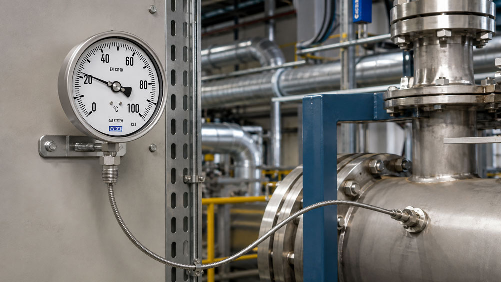
The temperature is to be measured on a hot pipeline, while the display must be installed several meters away on an easily accessible control panel. An electrical temperature measurement would generally be possible for such an application. However, in many machines and process plants, a purely mechanical gas-actuated thermometer with a remote capillary line is deliberately used.
The temperature sensor is installed directly at the process, while the display case is mounted separately at a remote location. Both components are connected by a thin capillary line. This makes it possible to display the temperature mechanically even where the actual measuring point is difficult to access, very hot or subject to strong vibration – without requiring auxiliary electrical power for the indication.
At first, the application seems straightforward: install the sensor at the process, route the capillary line to the desired display position and mount the case. In practice, however, the temperature range alone does not determine whether the measuring point will operate reliably. The capillary line is part of the actual measuring system and therefore cannot be routed, shortened or modified as freely as an ordinary cable.
Capillary length, ambient temperature along the line, temperature at the display case, permissible bending radius, mechanical protection and vibration must already be considered during planning. Sensor diameter, active sensor length, installation position and immersion depth are equally important. A technically perfect thermometer can still indicate an incorrect process value if, for example, the sensor extends only a few millimeters into a hot pipe and therefore loses too much heat through the process connection to the surrounding environment.
A thermowell also changes the measuring point. It improves mechanical protection and often allows the sensor to be removed without directly opening the process, but it also creates an additional thermal barrier between the medium and the sensor. This can significantly increase the response time.
The capillary line requires particularly careful handling. It does not merely connect two mechanical components but contains part of the measuring gas. A damaged or shortened capillary line therefore destroys the closed measuring system. Large temperature differences along a very long capillary can also influence the measurement under unfavorable conditions.
A gas-actuated thermometer with a remote capillary line should therefore be planned as a complete measuring system. Measuring range, sensor, insertion length, process connection, capillary length, routing, ambient temperatures, mechanical protection and display mounting location must all be matched to one another.
How Does a Gas-Actuated Thermometer Work?
A gas-actuated thermometer uses the temperature-dependent pressure change of an enclosed gas. The temperature sensor or stem, the capillary line and the measuring element in the display case together form a closed system filled with a suitable gas.
If the temperature at the sensor changes, the pressure inside this closed system also changes. This pressure acts on a Bourdon tube or similar measuring element inside the display case. Its mechanical movement is transferred through a movement mechanism to the pointer and displayed as a temperature value on the dial.
No electrical auxiliary power is required for the actual temperature indication. This is particularly useful for simple industrial measuring points, remote installations or applications where a purely mechanical display is deliberately preferred.
| Component | Function | Relevant Planning Factors |
|---|---|---|
| Temperature sensor | detects the process temperature | diameter, active length, installation position and immersion depth |
| Capillary line | transmits the pressure change to the display case | length, temperature, bending radius and mechanical protection |
| Measuring element | converts gas pressure into mechanical movement | ambient conditions at the display case |
| Movement and dial | provide the mechanical temperature indication | vibration, readability and mounting location |
A key difference compared with a conventional bimetal thermometer is that the measuring element and display can be physically separated. In a bimetal thermometer, the temperature-sensitive element is located directly at the stem. In a gas-actuated thermometer, the temperature-dependent pressure change can instead be transmitted through a capillary line to a display instrument mounted several meters away.
What Is the Function of the Capillary Line?
The capillary line connects the temperature sensor with the measuring element in the display case. It contains the same measuring gas as the sensor and is therefore part of the actual measuring system.
The small internal diameter of the capillary is important by design. The gas volume inside the line should remain as small as possible compared with the effective volume of the sensor, because the primary objective is to measure the temperature at the sensor rather than an average temperature of sensor, capillary line and measuring element.
The influence of ambient temperature can be significantly reduced or compensated by the design of the thermometer. Nevertheless, capillary length and thermal conditions are not arbitrary. A several-meter-long line that partly passes through a 20 °C control cabinet and then runs directly alongside a 100 °C hot pipe creates different requirements from a short capillary in a largely constant environment.
For this reason, the capillary should not be treated as an insignificant connection element only during installation.
How Long Can the Capillary Line Be?
The maximum possible capillary length depends on the specific thermometer type and its design. Industrial gas-actuated thermometers can be supplied with several meters of capillary and, depending on the version, with considerably longer remote lines.
However, this does not mean that the longest possible line should be selected as a precaution. The capillary should instead be only as long as required by the actual system layout. As the length increases, not only does the thermally influenced gas volume become larger, but the routing that must be mechanically protected and securely supported also becomes longer.
There is also a greater risk of kinks, abrasion and unfavorable routing through different temperature zones. An unnecessarily long capillary additionally creates excess line that later has to be accommodated in large loops.
| Planning Parameter | What to Consider | Typical Error |
|---|---|---|
| Direct distance | physical distance between sensor and display | using only the straight-line distance |
| Actual routing | bends, detours and machine construction | underestimating the installation route |
| Installation reserve | small additional length for clean installation | either no reserve or several meters of excess |
| Thermal environment | hot and cold sections of the route | choosing the shortest rather than the thermally best route |
| Mechanical protection | protective covering and fastening | improvising protection only on site |
For ordering, it is therefore not sufficient to specify only the geometric distance. A more useful basis is actual routing + bends + installation path + small service/installation reserve.
Why Does Ambient Temperature Influence the Measurement?
The measuring gas is not located only inside the temperature sensor. The capillary line, transition areas and measuring element also contain part of the gas charge. If the temperature of these areas changes, the pressure inside the closed system changes as well.
Industrial gas-actuated thermometers are designed to minimize this ambient-temperature influence as far as possible. However, the larger the gas volume outside the actual sensor and the greater the temperature fluctuations of this volume, the more important the thermal environment becomes.
Assume, for example, that the sensor remains constantly at 100 °C. The first half of the capillary is at 20 °C, while several additional meters run close to a hot process line and reach approximately 80 °C. The capillary is therefore heated considerably. In an unsuitable or insufficiently compensated configuration, this can influence the indication.
Particular attention is therefore required with long capillary lines, large temperature differences along the route, extreme ambient temperatures at the display case and applications with high accuracy requirements.
Planning the Capillary Routing Correctly
The shortest geometric route between sensor and display is not automatically the best routing path. In many cases, a slightly longer but thermally and mechanically more favorable route is the better solution.
Where possible, the capillary should not be routed directly alongside steam lines, exhaust lines or other hot process piping. Areas immediately next to furnaces, heating elements or strongly heated machine housings are equally unfavorable.
Mechanically, the remote line should not be routed over sharp sheet-metal edges, moving machine components or maintenance areas where tools or covers are regularly handled. At the same time, it should remain sufficiently accessible for inspection and installation.
Changing solar exposure can also be relevant. If one part of the capillary remains permanently in the shade while another section is exposed to strong sunlight, additional and possibly highly variable temperature gradients can occur.
Observe the Bending Radius of the Capillary Line
A capillary line can and usually must be bent during installation. However, it must never be kinked. The permissible minimum bending radius depends on the particular capillary design and any protective covering that may be fitted.
An excessively tight bend can deform the cross-section of the capillary tube and create a local mechanical weak point. More severe damage can cause the closed measuring system to leak and lose its defined gas filling.
Such a line cannot simply be repaired by cutting and reconnecting it in the same way as an electrical cable. The sensor, capillary and measuring element form one functional unit.
During installation, bends should therefore be smooth and generous, and repeated sharp rebending should be avoided. The manufacturer’s minimum bending radius must be observed.
Protect the Capillary Line Mechanically
The thin capillary line is often mechanically more sensitive than the robust display case or the temperature sensor itself. It is particularly vulnerable in maintenance areas, behind moving covers, at sheet-metal edges or wherever tools and other objects may come into contact with the line.
In such areas, a protective covering or spiral armor can be useful. This improves mechanical robustness but also affects the outside diameter, flexibility and possibly the required bending radius.
Mechanical protection should therefore preferably be specified when the thermometer is ordered. An improvised covering added later may place more stress on the capillary than it actually prevents.
Securing the Capillary Line Correctly
A capillary line should not hang freely and uncontrolled over long distances. Continuous movement and vibration can create mechanical stress, particularly at transition points.
However, the fastening must not crush the thin capillary. Suitable supports guide the line securely, have no sharp edges and apply only the amount of mechanical pressure required for secure retention.
Special attention should be paid to the transitions from the sensor to the capillary and from the capillary to the display case. Permanent tensile forces or severe bending and torsional loads should not be introduced at these points.
Thermal expansion should not be completely restricted either. A proper mounting system guides the line in a controlled manner without clamping it rigidly.
What Should Be Done with Excess Capillary Length?
A factory-filled capillary line must not simply be shortened to the desired length. Doing so would open the closed gas-filled measuring system and destroy the functionality of the thermometer.
A small installation reserve must therefore be accommodated through the routing. Large, stress-free loops that comply with the specified minimum bending radius are suitable for this purpose.
Very tight coils should be avoided. It is equally impractical to order several extra meters of line as a precaution and then simply coil up the excess during installation.
The technically better solution is a capillary length that is matched as closely as possible to the actual routing, with a reasonable installation reserve.
Choosing the Correct Sensor Position
Even a perfectly planned capillary line cannot compensate for an unsuitable sensor position. The temperature sensor must detect the temperature of the actual medium or process region of interest.
In a pipeline, the active sensor area should therefore extend as far as possible into a representative flow zone. Depending on the process, an installation directly at the pipe wall may produce a different value from the temperature in the center of the pipe.
Dead zones, areas with very low flow or positions directly downstream of a mixing point may also be unsuitable. In such locations, the medium may not yet be fully mixed or may exhibit local temperature gradients.
The correct installation position is therefore always a process-related decision and not merely a question of which threaded connection is available.
Ensuring Sufficient Immersion Depth
The temperature sensor has a thermally active area. This area should be exposed as completely as possible to the temperature that is actually being measured. If only a small part of the sensor is inserted into the medium, additional heat transfer takes place through the stem and process connection to the surroundings.
Assume, for example, that a liquid has a temperature of 180 °C. However, the sensor extends only a few millimeters into the pipeline, while the pipe wall, process connection and ambient environment are considerably cooler. Heat is then conducted away from the measuring zone through the metal of the sensor.
The indicated temperature can therefore be significantly lower than the actual medium temperature even though the thermometer itself is operating perfectly.
| Influence | With Unsuitable Design | Possible Consequence |
|---|---|---|
| Insufficient immersion depth | active sensor area not fully inside the process | measured value shifts toward ambient temperature |
| Massive process connection | high heat conduction | indication may be too low or too high |
| Low flow velocity | poor heat transfer to the sensor | slow and potentially inaccurate measurement |
| Large thermowell air gap | poor thermal contact | long response time |
| Sensor positioned unfavorably near the pipe wall | local wall temperature dominates | non-representative process value |
The required immersion depth depends, among other things, on sensor diameter, sensor design, temperature range, process connection and any thermowell that may be used.
Avoiding Heat Conduction Errors
Heat conduction is one of the most important installation influences in mechanical temperature measurement. It occurs whenever heat is transferred between the process and the surrounding environment through the sensor, stem or process connection.
Short insertion lengths in small pipes, large temperature differences between process and ambient conditions, massive metallic connections and low flow velocities are particularly critical. Under such conditions, the temperature at the active sensor area can differ significantly from the actual medium temperature.
A greater immersion depth often improves thermal coupling to the process. In small pipes, an angled installation, installation in a pipe bend or positioning against the direction of flow may also be useful, provided this is mechanically and process-technically permissible.
The objective is always to ensure that the temperature-sensitive area is surrounded as completely as possible by the medium or thermally dominated by it.
Influence of a Thermowell
In many industrial plants, the temperature sensor is not installed directly in the process medium but inserted into a thermowell. This provides considerable mechanical and operational advantages. The sensor can, for example, be replaced without directly opening the process and is better protected against process pressure, flow forces or aggressive media.
Thermally, however, an additional barrier is created. Heat must first be transferred from the medium to the thermowell and then from the thermowell to the temperature sensor. This increases the thermal mass and makes the measurement respond more slowly to rapid temperature changes.
The sensor and thermowell diameters should therefore be matched to one another. An unnecessarily large air gap further reduces heat transfer. Thermowell wall thickness, material, insertion length and flow conditions also influence the response time.
A thermowell should therefore not be selected only according to the matching process thread. Mechanical strength and thermal behavior must be considered together.
What Influences the Response Time?
A mechanical thermometer does not respond instantaneously to a change in temperature. The response time is determined by the complete heat-transfer path between the process medium and the temperature-sensitive area.
A thin sensor directly exposed to a fast-flowing liquid can respond relatively quickly. A massive thermowell in slowly moving air, on the other hand, has considerably greater thermal inertia.
In addition to sensor diameter and mass, the medium, flow velocity, thermowell design and heat transfer therefore play important roles.
If the indication responds slowly, a long capillary line should not automatically be assumed to be the primary cause. The thermal design at the actual measuring point is often much more important.
Mounting the Display Case Correctly
The main advantage of a remote capillary line is that the display case can be positioned independently of the actual measuring point. This freedom should be used in the design.
The case should be mounted in a location that is easy to read and access while also being exposed to moderate ambient temperatures and minimal vibration. Stable mechanical mounting is also important for reliable pointer indication.
For example, it would make little sense to use a remote thermometer and then install the display case directly above a very hot steam line. The capillary line is intended precisely to allow a thermally and mechanically more favorable mounting position.
Vibration and Capillary Lines
Strong vibration can place long-term stress on the mechanical movement of a thermometer. A remote capillary line allows the sensor and display to be separated so that the more sensitive display case can be removed from a highly vibrating area.
The sensor can, for example, be installed on a pump, compressor, motor or vibrating pipeline, while the display is mounted on a separate bracket or control cabinet.
However, the capillary line itself must not be forgotten. A freely vibrating section of line directly at the sensor or display case creates repeated bending loads at exactly the most sensitive transition points.
Even in high-vibration applications, the line therefore requires secure but low-stress mechanical routing.
Define the Capillary Length Before Ordering
The remote line of a gas-actuated thermometer is not ordinary accessory tubing that can be modified freely on site. It is part of the closed measuring system. The essential mechanical, thermal and process-related data should therefore already be known before ordering.
- Define the measuring or indication range.
- Determine the normal and maximum process temperature.
- Specify the process medium and process connection.
- Determine a suitable sensor diameter and required insertion length.
- Define the position of the display case.
- Measure the actual routing between sensor and display.
- Determine the required capillary length including a reasonable installation reserve.
- Evaluate ambient temperatures at the display case and along the capillary.
- Define any required mechanical protection for the capillary.
- Consider vibration affecting the sensor, capillary and display case.
- Determine whether a thermowell is required and which dimensions are appropriate.
A suitable capillary length should be planned and ordered. It should not be adapted during installation by shortening the line or creating improvised tight coils.
Practical Example: Temperature Display 8 m from the Process
In a production plant, the temperature of a hot liquid in a pipeline is to be measured. The measuring range is 0...200 °C. The pipeline is located behind a machine guard and is difficult to access during operation. The display is therefore to be installed on the operator side of the machine.
The direct geometric distance between the measuring point and the display panel is approximately 6 m. However, the line cannot be routed directly. It must first run upward, then around part of the machine and only afterwards to the control panel. The actual routing is therefore approximately 7.5 m.
Instead of simply ordering a much longer standard line, the actual route is used as the basis and a small installation reserve is added.
During route planning, it also becomes clear that the initially proposed path would run parallel to a hot steam line for several meters. The capillary is therefore routed at a suitable distance along a thermally more favorable path.
In the area of a maintenance opening, however, there is an increased risk of mechanical damage. A protected version or suitable mechanical routing is therefore provided at this location.
The sensor is installed so that its active area extends sufficiently into the liquid flow. The display case is mounted in a location that is easy to read, low in vibration and exposed to moderate ambient temperatures.
This makes full use of the main advantage of the remote thermometer: the temperature is measured directly in the process while the indication is positioned at a safely accessible and more favorable location for the instrument.
Systematically Troubleshooting Measurement Deviations
If a gas-actuated thermometer with a remote capillary shows an unexpected temperature value, it should not automatically be assumed that the calibration has changed or that the instrument is defective. The complete measuring point should first be examined.
As a first step, a suitable reference thermometer should be used to determine the actual temperature at the sensor location. It should then be checked whether the sensor is inserted deeply enough and whether its active area is actually surrounded by the medium whose temperature is to be measured.
If a thermowell is used, check whether the sensor is fully inserted and whether there is an excessively large air gap between the sensor and the thermowell. The capillary line should then be inspected for kinks, crushing, abrasion and unusually tight bends.
Thermally unusual sections of the line are also relevant. If part of the capillary now runs directly alongside a hot pipe or another heat source, the environmental conditions may have changed compared with the original installation.
The display case should then be inspected. It should remain within the permissible ambient conditions and should not be exposed unnecessarily to vibration or local heat sources.
If the deviation remains under controlled conditions, the complete thermometer assembly can be checked against a suitable temperature reference. The sensor, capillary and measuring element should be treated as one complete measuring system.
Common Planning and Installation Errors
- Ordering the capillary according to straight-line distance only: The actual installation route with bends and detours is longer.
- Selecting an unnecessarily long capillary: Large excess lengths later have to be accommodated in a mechanically and thermally unfavorable way.
- Shortening the capillary on site: This opens the closed gas-filled measuring system.
- Using too small a bending radius: The capillary tube can be deformed or permanently damaged.
- Kinking the capillary line: Such damage cannot simply be repaired like a conventional cable.
- Routing the remote line directly along a hot pipe: The capillary is unnecessarily exposed to strong thermal influence.
- Routing the capillary unprotected through maintenance areas: Mechanical damage from tools or covers becomes more likely.
- Clamping the line too tightly: The mounting can crush the thin capillary or create localized stress.
- Insufficient sensor immersion: Heat conduction through the stem and connection distorts the measured value.
- Inserting only the sensor tip into the process: The entire active sensor area does not reach the actual process temperature.
- Using an oversized thermowell or excessive air gap: The thermal response becomes unnecessarily slow.
- Mounting the display directly on a vibration source: The design advantage of the remote line is lost.
- Ignoring ambient temperature along the capillary: Long remote lines in particular can be more strongly affected.
- Automatically attributing a slow response to the capillary: Sensor design, thermowell and heat transfer are often the more important causes.
Suitable Gas-Actuated Thermometer
For industrial mechanical temperature measurements with a remotely mounted display, the WIKA Type 73 gas-actuated thermometer in the F73 version with capillary line is one possible solution. The instrument is designed for industrial applications in which the temperature sensor and display cannot be installed directly at the same location.
| Feature | Importance for the Application |
|---|---|
| Mechanical measuring principle | temperature indication without auxiliary electrical power |
| Remote capillary line | allows physical separation of sensor and display |
| Different capillary lengths | adaptation to the actual installation route |
| Different process connections | adaptation to pipeline, vessel or thermowell |
| Different sensor dimensions | adaptation of insertion length and thermal behavior |
| Optional capillary protection | improved mechanical robustness in industrial environments |
| Stainless steel design | suitable for demanding industrial conditions |
The exact configuration should be selected according to measuring range, process connection, installation point, required capillary length and the thermal and mechanical environmental conditions. An application-specific selection is particularly advisable for longer remote lines.
Further gas-actuated, bimetal, resistance and electronic thermometers as well as temperature sensors can be found under Temperature Measurement Technology at ICS Schneider.
Conclusion
A gas-actuated thermometer with a remote capillary line enables purely mechanical temperature indication at a location physically separated from the actual process. The temperature sensor can therefore remain directly at a hot, difficult-to-access or highly vibrating measuring point while the display case is mounted in a position that is easier to read and mechanically more favorable.
However, the capillary line is not an ordinary connection cable. It contains part of the gas filling and belongs to the closed measuring system. Its length, thermal exposure, minimum bending radius, fastening and mechanical protection must therefore be considered from the beginning.
An unnecessarily long remote line offers little practical advantage. Instead, it increases the thermally influenced gas volume and creates a longer routing path that must be mechanically protected. The capillary should therefore be selected as closely as possible according to the actual installation route.
Sensor installation is at least equally important for measurement quality. Insufficient immersion depth can cause significant errors through heat conduction. When a thermowell is used, its thermal mass, fit and any air gap between thermowell and sensor must also be considered.
A slow indication should not automatically be attributed to capillary length either. Sensor diameter, thermowell design, flow velocity and heat transfer often have a much greater influence on the dynamic response of the measuring point.
A reliable measuring point therefore depends on more than selecting the correct temperature range. The decisive factor is the complete system consisting of sensor, immersion depth, process connection, capillary length, routing, thermal environment, mechanical protection, thermowell and mounting location of the display.
FAQ: Gas-Actuated Thermometers with Capillary Lines
How does a gas-actuated thermometer with a remote capillary work?
The sensor, capillary line and measuring element form a closed gas-filled measuring system. When the temperature at the sensor changes, the internal pressure changes. This pressure acts on the measuring element in the display case and is converted through a mechanical movement into a temperature indication.
Does a gas-actuated thermometer require a power supply?
A purely mechanical gas-actuated thermometer does not require auxiliary electrical power for the actual temperature indication.
How long can the capillary line of a gas-actuated thermometer be?
The maximum possible length depends on the manufacturer, instrument type and specific version. Long remote lines are possible with industrial gas-actuated thermometers. However, the line should only be as long as actually required by the installation.
Does capillary length affect measurement accuracy?
Capillary length can be relevant because the remote line also contains measuring gas. The longer the capillary and the more its ambient temperature changes, the more important the instrument design, compensation and application-specific selection become.
Can a capillary line be shortened?
A factory-filled capillary line must not simply be shortened on site. The sensor, capillary and measuring element form a closed measuring system with a defined gas filling.
Can the capillary be bent?
Yes. However, the manufacturer’s specified minimum bending radius must be observed. The line must not be kinked, crushed or routed sharply over edges.
Can excess capillary line be coiled?
A small installation reserve can be routed in large, stress-free loops. Very tight coils should be avoided. It is better to specify a capillary length that matches the actual routing as closely as possible when ordering.
Can the capillary line be routed alongside a hot pipeline?
Strong additional heating should be avoided wherever possible. The remote line contains measuring gas and forms part of the measuring system. Large or strongly varying ambient temperatures must therefore be considered, particularly with long capillary lines.
Why does the thermometer indicate too low a temperature even though it is correctly calibrated?
One possible cause is insufficient immersion depth. If the temperature-sensitive area is not sufficiently heated by the process medium, heat can be conducted away through the stem and process connection to the cooler environment.
How deeply must the sensor be inserted?
The active or temperature-sensitive area should be exposed as completely as possible to the temperature being measured. The required minimum immersion depth depends, among other things, on sensor diameter, design, measuring range and installation conditions.
Does a thermowell slow down the temperature measurement?
Yes. Heat must first pass from the process medium through the thermowell and then to the sensor. Thermowell design, wall thickness, fit, medium and flow conditions therefore influence the response time.
Can a remote capillary line help in applications with strong vibration?
Yes. The sensor can remain at the vibrating measuring point while the more sensitive display case is mounted at a quieter location. The capillary line itself must also be routed and supported so that it is not continuously stressed by vibration.
What is particularly important when ordering a gas-actuated thermometer with a remote capillary?
In addition to the temperature range, the process connection, sensor diameter, insertion length, actual routing, required capillary length, display mounting location, ambient temperatures, vibration conditions and any required mechanical protection of the capillary should be defined.