


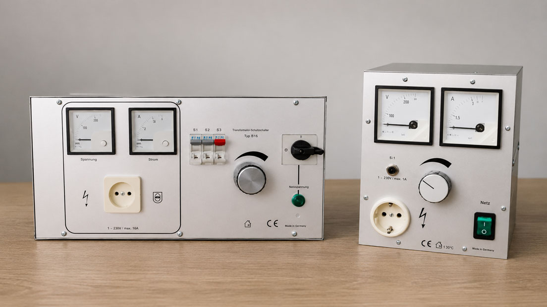
A variable AC voltage is required in the laboratory. A variable autotransformer, for example, provides 0 to 250 V AC and therefore initially appears to be exactly the right device. At the same time, however, the device under test must be galvanically isolated from the mains supply.
This is where a common selection error occurs:
An autotransformer can change the voltage – but it does not provide galvanic isolation.
An isolation transformer, on the other hand, performs a completely different function. Its primary and secondary windings are electrically separated from each other. This allows a secondary side that is galvanically isolated from the mains supply to be provided.
If an adjustable output voltage is also required, a variable isolation transformer can be used. This combines the galvanic isolation of an isolation transformer with an adjustable output voltage.
Products for laboratories, service and plant engineering can be found under Isolation transformers / variable transformers. Further solutions are grouped under Power supplies.
Table of Contents
- What is the fundamental difference between an isolation transformer and an autotransformer?
- How does an isolation transformer work?
- How does an autotransformer work?
- What does galvanic isolation mean?
- Distinguishing galvanic isolation from protective separation
- Is a variable transformer automatically galvanically isolated?
- When is a variable isolation transformer useful?
- Correctly dimensioning power, voltage and current
- What happens to grounding and protective earth?
- Correctly protecting the secondary side
- Leakage currents and measurements in the laboratory
- Taking transformer inrush current into account
- Typical applications in laboratory and service work
- Typical selection and application errors
- Recommended selection procedure
- Practical example
- Which products and solutions are suitable?
- Conclusion
- Frequently asked questions
What is the fundamental difference between an isolation transformer and an autotransformer?
Both devices operate with AC voltage and can change voltage ratios. However, their electrical construction differs fundamentally.
| Characteristic | Isolation transformer | Autotransformer |
|---|---|---|
| Windings | Separate primary and secondary windings | Common winding with tap |
| Galvanic isolation | Yes | No |
| Voltage conversion | Depending on transformation ratio | Yes |
| Variable output voltage | Only with a corresponding variable version | Possible with a variable autotransformer |
| Typical primary purpose | Electrical isolation | Efficient voltage conversion or adjustment |
The decision should therefore not be based solely on the required output voltage.
The most important question is:
Is galvanic isolation from the mains supply required or not?
How does an isolation transformer work?
A conventional isolation transformer has at least two electrically separated windings.
The primary winding is connected to the mains supply. Energy is transferred to the secondary winding via the magnetic field in the transformer.
There is no direct conductive connection between the primary and secondary windings.
An isolation transformer can, for example, operate with:
230 V input → 230 V output
.
Although the voltage remains almost unchanged, it still performs an important function: it galvanically isolates the secondary side from the primary mains supply.
An isolation transformer does not therefore necessarily have to change the voltage.
How does an autotransformer work?
An autotransformer operates with a common winding.
Part of the winding is shared by both the input and output sides.
In a variable autotransformer, the output voltage is adjusted via a movable tap on the winding.
This makes it possible, for example, to set output voltages from just a few volts up to approximately mains voltage or, depending on the version, above it.
The decisive point is:
There is an electrical connection between input and output.
The output therefore remains referenced to the mains supply.
A low adjusted output voltage does not automatically mean that the output is safely galvanically isolated from the mains.
What does galvanic isolation mean?
Galvanic isolation means that there is no direct conductive electrical connection between two circuits.
Energy or signals can nevertheless be transferred, for example:
- magnetically via a transformer,
- optically via an optocoupler, or
- capacitively via suitably designed coupling elements.
In an isolation transformer, energy is transferred magnetically.
This removes the direct electrical reference of the secondary side to the primary mains supply.
This is particularly important for certain testing, service and laboratory tasks.
Distinguishing galvanic isolation from protective separation
The terms galvanic isolation and protective separation should not simply be treated as identical.
Galvanic isolation initially describes a technical characteristic of the design.
A protective measure such as protective separation, on the other hand, requires the complete system to be designed and operated in accordance with the applicable electrical requirements.
This includes, among other things, the design of the transformer, secondary wiring, connected equipment and grounding conditions.
The presence of an isolation transformer therefore does not automatically mean that any downstream installation can be considered protective separation.
Is a variable transformer automatically galvanically isolated?
No.
The term variable transformer initially means only that the output voltage can be adjusted.
It does not clearly indicate whether galvanic isolation exists between input and output.
A typical variable autotransformer has a common winding and therefore provides no galvanic isolation.
This is particularly important in laboratory applications.
A device under test can, for example, be gradually powered from 0 V to 230 V using a variable autotransformer. Nevertheless, the circuit remains electrically connected to the mains supply.
If variable voltage and galvanic isolation are required, an appropriate combination or a variable isolation transformer is needed.
When is a variable isolation transformer useful?
A variable isolation transformer combines two functions:
- galvanic isolation from the mains supply and
- adjustable output voltage.
This is useful, for example, for:
- repair and testing of electrical devices,
- development work in electronics laboratories,
- controlled power-up of a device under test,
- functional testing under undervoltage or overvoltage conditions,
- test benches, and
- service work on mains-powered devices.
This allows a device under test to be switched on initially at a low voltage and then brought up to nominal voltage in a controlled manner.
Correctly dimensioning power, voltage and current
When selecting a transformer, output voltage alone is not sufficient.
At minimum, the following are decisive:
- input voltage,
- output voltage or adjustment range,
- permissible output current, and
- rated apparent power in VA.
For a simple AC load, the following approximation applies:
S = U × I
where:
- S = apparent power in VA,
- U = voltage in V, and
- I = current in A.
A 250 VA transformer can theoretically provide approximately:
250 VA / 230 V ≈ 1.09 A
at 230 V.
However, the current and power limits specified by the manufacturer are always decisive.
For motors, power supplies, transformers, capacitor-input circuits or other loads with high inrush currents, sufficient additional reserve should also be provided.
What happens to grounding and protective earth?
Galvanic isolation concerns the active circuit between the primary and secondary sides.
It does not mean that protective earth connections can be removed arbitrarily or that equipment housings should generally be operated without grounding.
The metal housing of a transformer, for example, may still be connected to earth via the protective conductor.
The decisive factors are the specific protective measure and the design of the secondary circuit.
It becomes particularly problematic if an originally earth-free secondary side is unintentionally reconnected to protective earth or ground through:
- oscilloscope ground,
- measuring instruments,
- USB connections,
- PC interfaces, or
- other grounded devices.
This can significantly change the electrical conditions of the test setup.
Correctly protecting the secondary side
A galvanically isolated secondary side also requires appropriate electrical design.
The transformer should not be regarded as a universal short-circuit or overload protection device.
Depending on the device, protective functions such as:
- fuse,
- thermal circuit breaker,
- temperature protection, or
- secondary-side current limiting
may be present.
For permanently installed applications, it must also be checked whether downstream conductors and loads require additional protection.
The protection must be suitable for the maximum available current, conductor cross-section and connected load.
Leakage currents and measurements in the laboratory
An isolation transformer is frequently used in the laboratory to interrupt the direct mains reference of a device under test.
This can be helpful, for example, for certain measurements using an oscilloscope.
Despite galvanic isolation, however, a real transformer is not an ideal, completely capacitance-free isolator.
Parasitic capacitances exist between the windings.
As a result, small capacitive currents can occur between the primary and secondary sides, particularly at higher frequencies.
For sensitive EMC, leakage-current or high-frequency measurements, the specific transformer design must therefore be taken into account.
Taking transformer inrush current into account
Transformers can briefly draw a considerably higher current when switched on than during steady-state operation.
The magnitude of this inrush current depends, among other things, on:
- transformer power,
- core design,
- switch-on point within the mains sine wave, and
- connected load.
With larger transformers, the upstream fuse may therefore trip even though the normal operating current is significantly lower.
Switch-on behaviour and manufacturer specifications should therefore also be considered during system design.
Typical applications in laboratory and service work
A common task is the repair of a mains-powered electronic device.
The technician wants to:
- galvanically isolate the device from the mains,
- slowly increase the input voltage, and
- monitor current and voltage at the same time.
A pure variable autotransformer fulfils only the second requirement.
It provides a variable output voltage but no galvanic isolation.
A pure isolation transformer, on the other hand, provides the isolation function but, in a 230 V / 230 V version, delivers a fixed output voltage.
A variable isolation transformer is the appropriate device class when both functions are required.
Typical selection and application errors
| Observation or assumption | Problem | Recommended check |
|---|---|---|
| “The variable transformer is set to 50 V, so the voltage is safely isolated from the mains.” | Variable autotransformer provides no galvanic isolation | Check transformer design |
| Isolation transformer selected only by wattage | Apparent power and output current are not taken into account | Check VA rating and maximum current |
| Device under test is powered through an isolation transformer and an oscilloscope is connected | Measuring instrument can establish a new ground reference | Consider the complete measurement setup |
| Fuse trips when a large transformer is switched on | High inrush current possible | Check switch-on behaviour and protection |
| Several loads are connected to an isolated secondary side | Protective concept changes | Review electrical protection concept |
| Output voltage drops significantly | Transformer overloaded or undersized | Compare load current and rated power |
| Isolation transformer is assumed to provide automatic personal protection | Protective effect depends on the complete system design | Evaluate the protective measure of the entire installation |
Recommended selection procedure
- Define the application: Voltage conversion, galvanic isolation or both?
- Determine mains voltage: For example 230 V or 400 V.
- Determine output voltage: Fixed or variable?
- Clarify galvanic isolation: If required, do not use a pure autotransformer.
- Determine maximum load current: Take the load’s continuous current into account.
- Calculate apparent power: Dimension the transformer sufficiently in VA.
- Consider inrush current: Especially for motors, power supplies and larger transformers.
- Check protection: Consider the primary and secondary sides according to the application.
- Define grounding conditions: Take protective earth and possible ground connections through measuring instruments into account.
- Check the measurement setup: Oscilloscopes, PCs and other devices can create galvanic connections.
- Select housing and connection type: Benchtop unit, fixed installation, socket or terminals.
Practical example
In a service workshop, an electronic 230 V device is to be switched on for the first time after repair.
The technician wants to set the voltage low initially and increase it slowly.
A variable autotransformer with an output of 1 to 250 V AC is available in the workshop.
At first glance, the device appears ideal.
However, the device under test must also be galvanically isolated from the mains supply.
The variable autotransformer alone is therefore unsuitable because a conductive connection remains between input and output.
A variable isolation transformer is used instead.
This provides a galvanically isolated output while also allowing the output voltage to be adjusted.
The device under test is initially switched on at low voltage.
The voltage is then increased in a controlled manner while current consumption and device behaviour are monitored.
Before additional measuring instruments are connected, it is also checked whether, for example, the ground connection of an oscilloscope would introduce an unwanted earth reference into the test circuit.
The example shows:
Output voltage alone does not determine which transformer is suitable. Galvanic isolation and the complete test setup are also decisive.
Which products and solutions are suitable?
Isolation transformers – galvanically isolated fixed voltage
Various devices with a galvanically isolated secondary side are available under Isolation transformers.
The product range includes, for example, versions with 230 V input and 230 V output as well as different power ratings.
They are particularly suitable when a galvanically isolated supply is required but a variable output voltage is not necessary.
5357 Series – isolation transformers in enclosures
The ICS product range of 5357 isolation transformers includes versions from 250 VA up to the kVA range.
Such devices are suitable, for example, for laboratories, service, test stations and installations where a galvanically isolated AC supply is required.
5358 Series – variable autotransformers
The 5358 variable autotransformers provide a variable AC voltage.
Depending on the version, different maximum output currents are available.
Important:
These devices are not galvanically isolated between input and output.
They are therefore particularly suitable where an adjustable AC voltage is required but galvanic isolation is not part of the requirement.
5315 Series – variable isolation transformers
The variable isolation transformers combine an adjustable output voltage with galvanic isolation.
For example, with a 230 V AC input, the 5315.3 provides an adjustable output voltage from 1 to 250 V AC with a galvanically isolated, earth-free output.
This device class is therefore particularly suitable for laboratory and service applications in which a device under test must be both galvanically isolated and supplied with variable voltage.
Further devices and power supply solutions can be found under Power supplies.
ICS Schneider Messtechnik supports you in selecting isolation transformers, variable autotransformers and variable isolation transformers as well as in dimensioning voltage, current and power for laboratory, service and plant applications.
Conclusion
Isolation transformers and autotransformers can both change AC voltages, but they perform electrically different tasks.
The most important difference is:
An isolation transformer provides galvanic isolation. An autotransformer does not.
A variable autotransformer is an excellent choice when a variable AC voltage is required and an electrical connection to the mains supply is acceptable.
An isolation transformer, on the other hand, is used when the primary and secondary circuits must be electrically separated from each other.
If both functions are required, a variable isolation transformer is used.
When selecting a device, output voltage and power must not be considered in isolation. Output current, apparent power, inrush current, protection and grounding conditions are also part of the design.
Particularly during laboratory and service work, the complete test setup must be considered. An additionally connected oscilloscope, PC or other grounded measuring instrument can reconnect the originally earth-free secondary side to ground.
The correct selection therefore does not begin with the question “How many volts do I need?”, but with:
Do I need voltage conversion, galvanic isolation or both?
Frequently asked questions about isolation transformers and autotransformers
What is the most important difference between an isolation transformer and an autotransformer?
An isolation transformer has separate primary and secondary windings and therefore provides galvanic isolation. An autotransformer uses a common winding, meaning there is an electrical connection between input and output.
Is a variable transformer automatically an isolation transformer?
No. Many variable transformers are variable autotransformers and do not provide galvanic isolation. The exact device design must be checked.
What is an isolation transformer used for?
It is used when a circuit must be galvanically isolated from the mains supply, for example for certain laboratory, testing, service and maintenance tasks.
Can an autotransformer be used for repair work?
It can be used to provide a variable AC voltage. However, if the test setup also requires galvanic isolation, a variable autotransformer alone is not sufficient.
What is a variable isolation transformer?
A variable isolation transformer combines galvanic isolation with an adjustable output voltage. It is therefore particularly suitable for laboratory and service applications.
Is an output voltage of 50 V from a variable autotransformer galvanically isolated from the mains?
No. A low output voltage does not change the fundamental design of the autotransformer. An electrical connection remains between input and output.
Does the secondary side of an isolation transformer have to be grounded?
This depends on the intended protective measure and the electrical installation. An originally earth-free secondary side should not be arbitrarily connected to ground without considering the complete protection concept.
Can an oscilloscope affect galvanic isolation?
Yes. With mains-powered oscilloscopes, the ground connection or protective earth can introduce an earth reference into the test circuit. The complete measurement setup must therefore be considered.
How is the required transformer power calculated?
For a simple AC load, the required apparent power can be approximated from voltage × current. The type of load, inrush current and power reserve must also be taken into account.
When is an autotransformer useful?
An autotransformer is useful when AC voltage needs to be efficiently converted or continuously adjusted and galvanic isolation is not required.