


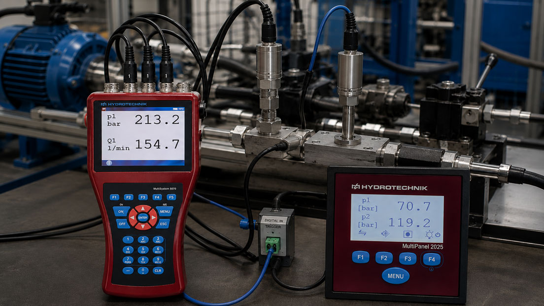
Three data loggers are monitoring a test bench simultaneously. One device records pressure, another temperature and a third motor current. After a fault occurs, the objective is to determine what happened first. However, the measurement data initially appear to show the temperature rising first, followed by a pressure drop and only several seconds later an increase in current. From a technical perspective, this sequence does not make sense.
The cause does not necessarily lie within the process itself. Even a time offset of only a few seconds between the internal clocks of different data loggers can place events in the wrong sequence when the measurement series are subsequently combined. During long-term measurements, drift between the individual clocks must also be taken into account.
For a reliable root-cause analysis, it is therefore not sufficient to set all devices to the same time before starting the measurement. Start offset, clock deviation, time zone, daylight saving time, measurement interval, trigger timing and, where applicable, even the time delay between individual measurement channels must also be considered.
Suitable devices for parallel measurements can be found under Multimeters / data loggers. Further solutions for long-term and multi-channel data acquisition are grouped under Data loggers / universal measuring instruments.
Table of Contents
- Why the same clock time does not yet mean synchronisation
- Distinguishing offset, drift and channel delay
- How does a data logger’s clock deviation occur?
- Using PC and NTP time correctly
- Why a common start trigger is more accurate
- Using a synchronisation pulse during an ongoing measurement
- Handling time zones and daylight saving time unambiguously
- Considering measurement intervals and sampling grids
- Are all channels of a logger really measured simultaneously?
- Time offset caused by the sensor itself
- Correcting clock drift retrospectively
- Combining measurement data correctly
- Typical fault patterns
- Recommended procedure for synchronised measurements
- Practical example from a test bench
- Documenting synchronisation
- Which products and solutions are suitable?
- Conclusion
- Frequently asked questions
Why the same clock time does not yet mean synchronisation
If two data loggers are manually set to 08:00 before a measurement, this initially means only that their displays show approximately the same time.
A small time offset can already occur during the setting process. If Logger A is started at 08:00:00 and Logger B is not confirmed until three seconds later, the two datasets already have an initial offset.
Afterwards, both devices continue to run using their own internal time bases. These may run at slightly different speeds. After several hours or days, the time offset may therefore be greater than it was immediately after the start.
For a simple room temperature measurement, a difference of a few seconds is usually irrelevant. On a test bench where pressure peaks, valve switching operations, current increases or rapid mechanical events are to be compared, the same error can completely change the interpretation.
Distinguishing offset, drift and channel delay
When measurement data do not match in time, three different effects should be considered separately.
| Effect | Meaning | Typical behaviour |
|---|---|---|
| Time offset | The clocks start with different time values | Constant offset throughout the measurement |
| Clock drift | The time bases run at slightly different speeds | The offset increases or decreases with measurement duration |
| Measurement or channel delay | Measured values are technically not acquired at exactly the same time | Small systematic offset despite correct clocks |
The distinction is important. A constant offset can be corrected relatively easily. In the case of drift, however, it must also be taken into account that the time error changes over the duration of the measurement.
How does a data logger’s clock deviation occur?
Stand-alone data loggers require an internal clock or time base so that every stored measurement value can be assigned to a specific point in time.
However, this clock does not run mathematically perfectly. The oscillator used has a limited frequency accuracy and may also be influenced by temperature, ageing and the device design.
The possible deviation of a time base is often expressed as a frequency deviation. A specification in ppm – parts per million – can be directly related to the possible time drift.
In simplified form:
Time deviation ≈ measurement duration × frequency deviation
As a purely numerical example, 20 ppm corresponds to approximately 1.7 seconds per day. After seven days, this would already amount to around 12 seconds if the deviation remained constant in the same direction.
This value is explicitly not a general limit for data loggers. The actual time base of the specific device must be assessed using the technical data or manufacturer information.
The example nevertheless illustrates why synchronising the devices only once before a measurement lasting several weeks is not necessarily sufficient.
Using PC and NTP time correctly
Many data loggers are configured via a PC, software package or network. In many cases, the internal clock of the logger can be set to the current system time.
This significantly improves the initial situation if all devices are configured one after another using the same computer.
For network-enabled devices, synchronisation via a common time service may be useful – provided that the respective device supports it. NTP, the Network Time Protocol, is used to synchronise the clocks of distributed systems to a common time reference.
However, an important distinction must be made:
A common clock time does not guarantee that two measuring instruments acquire their measured values at exactly the same moment.
NTP or PC-based time synchronisation primarily addresses the time base. For fast events, an additional common hardware trigger may be required.
It should also never be assumed automatically that a device with an Ethernet interface supports NTP synchronisation. This function must be explicitly supported by the specific data logger model.
Why a common start trigger is more accurate
If several loggers are to compare a fast event, a common electrical start signal is often considerably more precise than manually starting the devices.
The prerequisite is that the data loggers being used have an appropriate trigger or digital input.
A common trigger can, for example, originate from a test bench controller, PLC or defined switching contact. The same change of state is provided to the participating measuring instruments as a common time reference.
This makes it possible to create a common point in the measurement curves:
t = 0 corresponds to the trigger event.
The absolute time can still be documented. For technical root-cause analysis, however, the relative time with respect to the trigger is also used.
This makes it possible to determine clearly, for example, whether a pressure increase occurred 150 ms before or 300 ms after a valve was switched.
When making the electrical connection, the supported trigger levels, ground references, galvanic isolation and permissible voltages of the respective devices must be taken into account. Trigger connections must not be connected solely because they have similar terminal designations.
Using a synchronisation pulse during an ongoing measurement
For longer measurements, the common start is not the only relevant point. A defined synchronisation pulse during or at the end of the recording can additionally indicate how far the logger clocks have drifted apart.
A practical method is for all participating devices to record the same pulse at the beginning. After several hours or days, a second common pulse is generated.
If the second pulse occurs in the dataset of Logger A at 24:00:00 and in Logger B at 24:00:03, an additional relative offset of three seconds has developed between the two time bases.
For particularly important long-term measurements, regularly recurring synchronisation events can also be used.
This makes it much easier to determine later whether there is only a constant offset or whether the time base of one logger is drifting relative to another.
Handling time zones and daylight saving time unambiguously
Two technically correct logger clocks may still appear to be one hour apart if different time-zone or daylight-saving-time settings are used.
This problem occurs particularly frequently when:
- data from different software packages are combined,
- measurements span a daylight-saving-time change,
- devices from different countries are used, or
- one system stores UTC while another stores local time.
A uniform time base is therefore advisable for demanding measurement campaigns. UTC is particularly suitable for internal storage and data merging because it remains independent of local daylight-saving-time changes.
Local time can subsequently be derived from UTC for reports or operator displays.
The decisive factor is less whether UTC or local time is used and more that it is clearly documented which time base each dataset contains.
Considering measurement intervals and sampling grids
Even perfectly synchronised clocks do not solve every problem.
Logger A, for example, records every 100 ms, Logger B once per second and Logger C only every ten seconds. The stored values cannot then simply be compared row by row.
An event occurring at 12:00:00.650 may be captured directly by a fast logger, while a slower logger may not store a new value until 12:00:01 or even considerably later.
The event therefore appears to be shifted in time even though the clocks are correctly synchronised.
Before starting the measurement, the following points should therefore be coordinated:
- measurement interval,
- sampling rate,
- storage rate,
- trigger conditions, and
- required time resolution.
The fastest possible measuring rate is not automatically the best choice. It must be appropriate for the dynamics of the process being investigated.
Are all channels of a logger really measured simultaneously?
Even with a single multi-channel data logger, it should be checked how the channels are technically acquired.
In simultaneously sampled systems, every relevant channel has its own acquisition path at the same point in time or an architecture designed accordingly.
Other measuring instruments, however, use a multiplexer. In this case, several input channels are switched very quickly one after another to a common A/D converter.
There is then a small time difference between channel 1 and channel 8. For slow temperature measurements, this effect is often negligible in practice. For rapidly changing current, pressure, vibration or pulse signals, however, it can become relevant.
It is therefore necessary to distinguish between two specifications:
How often is a complete measurement sequence stored – and what is the time interval between the acquisition of the individual channels within that sequence?
For high-speed test bench analyses, the channel architecture of the measuring instrument used should therefore be included in the assessment.
Time offset caused by the sensor itself
An apparent time offset does not necessarily originate from the data logger.
Different sensors have very different dynamic characteristics. An electrical current sensor can detect a change very quickly, while a temperature probe may respond significantly later because of its thermal mass.
Pressure sensors, thermocouples, Pt100 probes and humidity sensors also have different response times depending on their design and installation.
If, for example, the current rises immediately after a pump is started, the pressure increases a few milliseconds later and the housing temperature does not respond until several minutes later, this sequence is physically plausible.
During evaluation, it is therefore necessary to distinguish between:
- clock offset,
- measurement interval,
- electronic channel delay, and
- physical sensor response.
Correcting clock drift retrospectively
If it is only discovered after the measurement has been completed that two loggers are no longer aligned in time, retrospective correction may be possible.
A constant offset is the simplest case. If it is known that Logger B was exactly 4.2 seconds behind Logger A throughout the measurement, its timestamps can be shifted accordingly.
Drift is more complex.
Assume that two loggers are exactly aligned at the start. After ten hours, Logger B is two seconds behind. In this case, an approximate time-dependent correction can be applied within the measurement, provided that the drift was sufficiently uniform.
Two or more clearly identifiable common events are particularly helpful for this purpose:
- synchronisation pulse at the beginning,
- synchronisation pulse at the end,
- common valve switching event,
- defined load step, or
- another event that can be assigned with certainty.
The original dataset should always remain unchanged. A time-corrected file should be identified as processed evaluation data and the correction method used should be documented.
Combining measurement data correctly
When CSV, Excel or other export files from different loggers are combined, the first step should not be to graphically overlay the curves.
The time axes must first be standardised.
A useful sequence is:
- Determine the time format of each logger.
- Check the time zone or UTC reference.
- Determine the start offset.
- Check for possible drift.
- Define a common reference time.
- Compare measurement intervals or sampling rates.
- Only then merge or resample the datasets.
If the measurement intervals differ, a common time axis can be generated. However, interpolation must be used with caution.
Between two temperature values, linear interpolation may be appropriate for displaying a trend. For a digital switching state or a short pressure peak, however, the same method could generate an event that was never physically measured.
Original measurement values and mathematically generated intermediate values should therefore remain distinguishable.
Typical fault patterns
| Observation | Possible cause | Recommended check |
|---|---|---|
| Two curves are permanently offset by several seconds | Different start time or clock offset | Find a common event and determine the offset |
| The offset becomes increasingly larger during the measurement | Clock drift | Compare a reference event at the beginning and end |
| The offset is exactly one hour | Time zone or daylight saving time | Check the time base and software settings |
| A fast channel appears to respond earlier than a slower logger | Different measurement intervals | Compare sampling and storage rates |
| Channels of the same device show a small fixed offset | Possible sequential channel sampling | Check the measuring principle and channel sampling architecture of the device |
| Temperature responds significantly later than current or pressure | Physical sensor inertia | Compare response times and installation conditions |
| Dataset contains duplicate or missing times | Time change or retrospective clock correction | Check UTC time or raw timestamps |
Recommended procedure for synchronised measurements
- Define the measurement task: Specify which events are to be compared with one another in time.
- Define the required time resolution: Are minutes, seconds, milliseconds or even shorter intervals relevant?
- Use a common multi-channel logger where possible: This eliminates a large proportion of the synchronisation problems between separate devices.
- Define a common time base: For example, UTC or the same PC or network time.
- Synchronise the loggers immediately before starting the measurement: Check date, time and time zone.
- Coordinate measurement intervals: The time resolution of all devices must be appropriate for the event dynamics.
- Use a common trigger: If supported by the devices and fast events are being investigated.
- Document a synchronisation event: Generate a clearly identifiable common pulse at the beginning.
- Re-reference during long-term measurements: Record another synchronisation pulse at the end or at regular intervals.
- Preserve the raw data: Do not overwrite original files.
- Check the time axes: Evaluate offset, drift, time zone and channel delays.
- Document the evaluation: Record every retrospective time correction in a traceable manner.
Practical example from a test bench
A sporadic fault is to be investigated on a hydraulic test bench. One logger records pump pressure, a second records motor current and a third records several temperatures.
In the morning, all devices are manually set to the same displayed time and then started.
After several hours, the fault occurs. During evaluation, it initially appears that the pressure drop occurred several seconds before the increased motor current. The suspected cause does not match the behaviour of the system.
The datasets are then compared using a switching event that was recorded by all three measuring systems. This reveals that the loggers already had different time offsets at the start of the measurement.
A second common event towards the end of the measurement is also evaluated. The distance between the time axes has increased further by this point. It is therefore clear that a small relative clock drift is present in addition to the initial offset.
The raw data are not modified. Copies are created for the root-cause analysis and corrected to a common relative time axis using the two reference events.
After correction, a different sequence becomes apparent: first the motor current rises, shortly afterwards the pressure changes. Because of its considerably slower thermal dynamics, the temperature does not respond until much later.
The setup is modified for the next test series. Several of the required signals are acquired using a common multi-channel measuring instrument. A common digital trigger is additionally used for the remaining external measuring device.
This means that the time relationship is already defined during measurement planning and no longer has to be reconstructed retrospectively.
Documenting synchronisation
Especially for complaints, test benches and long-term root-cause analyses, the time configuration should form part of the measurement documentation.
At minimum, the following information is useful:
- device designation and serial number,
- measurement channel and assigned measured variable,
- start and end time,
- time zone or UTC used,
- measurement or storage interval,
- type of clock synchronisation,
- trigger used,
- time of synchronisation pulses,
- identified time offset,
- identified drift, and
- any retrospective correction of the time axis.
This makes it possible even months later to determine whether a time difference between two events actually originated from the process or was caused by the measuring equipment.
Which products and solutions are suitable?
MultiSystem 5070 – multiple measured variables on a common time base
The MultiSystem 5070 is particularly suitable for mobile diagnostics and test-bench applications in which several measured variables need to be considered together.
The device provides multiple analogue or frequency inputs, one digital input and output, as well as additional channels for calculations and CAN data. A large number of measured variables can therefore be acquired within one common measuring system.
For the application described here, a major advantage is the ability to record as many related signals as possible within a single device. This eliminates the need to synchronise several independent logger clocks for these channels.
With suitable configuration, the digital input can also be used for event-related triggering or as a time reference.
ICT700 / ICT750 – stationary multi-channel acquisition with trigger functions
The ICT700 / ICT750 are suitable for stationary multi-channel measurement applications.
The devices enable the acquisition of numerous channels and provide different measuring rates, extensive trigger functions and interfaces such as Ethernet and USB.
Particularly on test benches, central acquisition of different analogue process signals can significantly reduce the subsequent effort required to combine several individual logger datasets in time.
MultiPanel 2025 – data acquisition with trigger input and output
The MultiPanel 2025 combines measured-value display and data recording and provides trigger inputs and outputs.
This can make the device useful for applications in which a defined external event is intended to serve as the time reference for a recording.
Whether several devices can be connected via a particular trigger architecture must be checked against the specific electrical input and output specifications.
Further multi-measuring and data acquisition systems can be found under Multimeters / data loggers. The complete range is grouped under Data loggers / universal measuring instruments.
ICS Schneider Messtechnik supports you in selecting data loggers, sensors, measurement rates and trigger concepts as well as in planning multi-channel measurements for test benches, maintenance and root-cause analysis.
Conclusion
Multiple data loggers do not automatically show the same time simply because their clocks were set identically before the measurement began.
For the correct combination of parallel measurement series, at least the initial offset, clock drift, time zone, measurement interval and possible channel delays must be taken into account.
For slow long-term measurements, a common PC or network time can already provide a very good starting point. When fast events are being compared, however, a common hardware trigger or synchronisation pulse is considerably more informative.
During long measurements, it should also be checked whether the time offset between the devices changes. A reference event at the beginning and a second at the end make it possible to identify relative drift and, if necessary, correct it in a traceable manner.
Wherever possible, it is technically easier to acquire related measured variables using a common multi-channel data logger. This means that pressure, temperature, current or other signals are already assigned to a common time base within one measuring system.
Ultimately, the time base must be treated just as carefully as measuring range, sensor selection and measurement accuracy. Only then can it later be reliably determined which event was actually the cause and which was the effect.
Frequently asked questions about synchronising multiple data loggers
Is it sufficient to set all loggers to the same time before starting?
For slow and non-critical recordings, this may be sufficient. For precise root-cause analyses, however, it is also necessary to consider how accurately the devices were started and how much their internal clocks drift during the measurement.
What is the difference between time offset and clock drift?
An offset is an existing time difference between two clocks. Drift means that this difference becomes larger or smaller during the measurement because the two time bases run at slightly different speeds.
Can NTP synchronise multiple data loggers exactly?
NTP can provide a common time base for suitably equipped network devices. However, it does not automatically guarantee exactly simultaneous acquisition of measurement values. For fast events, additional hardware triggering may be required.
Why should UTC be used for long-term measurements?
UTC avoids ambiguity caused by local time zones and daylight-saving-time changes. A common time base simplifies evaluation particularly when combining datasets from different systems or locations.
What is a synchronisation pulse?
A synchronisation pulse is a defined signal or event that is acquired by several measuring systems. Its position in the datasets serves as a common time reference point.
Can I correct a time offset retrospectively?
Yes, if the offset can be determined reliably. A constant offset can be corrected relatively easily. In the case of drift, at least two common reference events distributed over the measurement period are considerably more useful.
Why do two channels of the same data logger sometimes not match exactly in time?
Some measuring systems acquire several channels sequentially via a multiplexer. This creates a small time difference between the channels. Whether this is relevant depends on the speed of the process and the architecture of the device.
Can a slow sensor look like an incorrect clock?
Yes. A temperature probe, for example, may respond much more slowly to a process change than a current or pressure sensor. This physical time offset must be distinguished from an error in the logger time base.
Which is better for root-cause analysis: several individual loggers or one multi-channel logger?
If all required measured variables and signals can be acquired using one common multi-channel logger, this greatly simplifies their time correlation. Separate loggers remain useful when measuring points are far apart or specialised measuring instruments are required.
What should be documented when applying a retrospective time correction?
The original dataset, the identified time deviation, the reference events used, the correction method and the resulting evaluation file should be documented in a traceable manner. The original data should remain unchanged.