


In hydraulic test benches, machine test benches and development environments, it is often not enough to look at the volume flow only statically. Especially during test cycles, load changes, valve switching operations, pump tests or functional tests, it must be visible how quickly the flow changes and whether the system operates stably under real operating conditions.
Measuring turbines are particularly interesting for such tasks because they can capture rapid changes in volume flow and output them as a frequency or pulse signal. This allows dynamic processes to be integrated well into data acquisition, test bench software or mobile measuring systems. Especially in hydraulics, this is helpful when pumps, valves, motors, cylinders or complete assemblies need to be tested.
This article explains when a measuring turbine is useful in a test bench, what to consider regarding hydraulic oil, temperature, viscosity, installation and calibration, and how measured values can be evaluated meaningfully during the test cycle. The focus is not only on the sensor itself, but on the entire measuring section consisting of medium, installation location, signal, data acquisition and interpretation.
Table of contents
- Basics: How a measuring turbine captures volume flow
- Why measuring turbines are particularly useful in test benches
- Dynamic flow measurement: Making rapid changes visible
- Hydraulic oil, temperature and viscosity as influencing factors
- Installation in the test section: What is important for stable measured values
- Frequency output, pulses and data acquisition
- Calibration and K-factor: Why the evaluation must be correct
- Tables: Selection, influencing factors and evaluation
- Practical example: Pump testing with a measuring turbine
- Which measuring instruments / products are suitable?
- Conclusion: Measuring turbines are strong when dynamics must become visible
- FAQ: Frequently asked questions about measuring turbines in test benches
Basics: How a measuring turbine captures volume flow
A measuring turbine uses a turbine wheel that is driven by the flowing medium. The rotational speed of the turbine wheel has a defined relationship to the volume flow. The higher the flow rate, the faster the turbine rotates. This rotation is detected by a signal pickup and converted into an electrical signal.
In many applications, the signal is output as a frequency or pulse signal. The frequency increases with the volume flow. Using a K-factor or device-specific calibration, the actual volume flow can be calculated from the pulses or frequency.
The major advantage in the test bench lies in the fast signal response. When valve positions change, pump speeds vary or load cycles are run, a measuring turbine can make such changes very clearly visible. This makes it suitable not only for simple flow indication, but also for dynamic analysis of test sequences.
At the same time, it must be considered that measuring turbines have a moving measuring element. Cleanliness of the medium, viscosity, temperature, installation conditions and calibration have a direct influence on measurement quality. A measuring turbine is therefore not just any flow meter, but must be designed to match the test task.
Why measuring turbines are particularly useful in test benches
In a test bench, components, assemblies or complete systems are tested under defined conditions. In many cases, not only a single final value is of interest, but the behavior over the entire test cycle. This is exactly where measuring turbines offer a practical advantage.
For example, a hydraulic pump can be tested to see how the volume flow changes as the load increases. With a proportional valve, it can be made visible whether the flow increases proportionally to the control signal. With a hydraulic motor, the flow can be compared with speed, pressure and temperature. In quality assurance, it can be checked whether a component operates within defined tolerances.
Because measuring turbines provide a fast signal, they are particularly interesting when short events need to be captured. A slow or heavily damped flow meter can smooth rapid changes and therefore hide important information. A measuring turbine, on the other hand, can help detect load changes, jumps, pulsations or short deviations during the test cycle.
For the measurement to be meaningful, however, the measuring turbine must match the expected flow rate, the medium, the pressure range, the temperature and the data acquisition system. The test bench should therefore be planned not only mechanically, but also from a measurement technology perspective.
Dynamic flow measurement: Making rapid changes visible
Dynamic flow measurement means that not only a stable average value is considered, but the time profile of the volume flow. In the test bench, this is particularly important when components are tested under changing operating conditions.
One example is a test cycle in which a valve is opened and closed several times. The final value alone only indicates which flow rate is achieved at a certain position. The profile additionally shows how quickly the system reacts, whether overshoots occur, whether the flow fluctuates or whether a temperature or viscosity influence becomes noticeable after several cycles.
The profile is also important in pump testing. A pump may appear inconspicuous at a static measuring point, but show drops, pulsations or delayed reactions during rapid load changes. Exactly such effects are often decisive for development, diagnostics and quality testing.
The measuring turbine provides a signal for this that can be recorded with suitable data acquisition. The decisive factor is that sampling rate, signal processing and software evaluation match the dynamics of the test cycle. A fast sensor is of little use if the data acquisition is set too slowly or if the value is smoothed too strongly in the software.
Hydraulic oil, temperature and viscosity as influencing factors
In hydraulic test benches, the medium is usually hydraulic oil or another mineral oil-based fluid. The viscosity of the oil depends strongly on temperature. Cold oil is more viscous, while warm oil flows more easily. As a result, the behavior of the measuring turbine can change as the system reaches operating temperature during the test sequence.
This influence is very important in practice. If a measuring turbine is calibrated only at a certain viscosity, a significant deviation in the actual oil viscosity can influence measurement accuracy. In test benches with strongly varying temperatures, long test series or different oil types, it should therefore be checked particularly carefully how viscosity is taken into account.
Modern measuring turbine solutions can partially account for this dependency through special calibration, stored oil characteristic curves or temperature compensation. This is particularly useful when measurements are not always performed at exactly the same operating temperature or when different hydraulic media are used.
For a clean assessment, the temperature in the test bench should be documented. If the volume flow changes during a test cycle, the cause may lie in the component, but also in the change in temperature and viscosity of the medium. Without this additional information, interpretation quickly becomes uncertain.
Installation in the test section: What is important for stable measured values
Even the best measuring turbine only delivers good results if it is installed correctly in the test section. The installation location should be chosen so that the medium flows evenly through the turbine and no strong flow disturbances occur directly upstream of the sensor.
Strong changes in cross-section, tight bends, valves, throttles or pump outlets directly upstream of the measuring turbine can influence the flow profile. Depending on the setup, this can lead to unstable measured values or systematic deviations. This point is often underestimated, especially in compact test bench designs.
The cleanliness of the medium is also crucial. Dirt particles can impair the turbine wheel, cause wear or distort the measurement. The system should therefore be flushed clean before installation and the measuring section should be properly vented. Air in the system can also lead to fluctuating or implausible measured values.
At high pressures and in hydraulic test benches, mechanical design, suitable fittings, seals and safe installation are also important. Work on hydraulic systems and test benches may only be carried out by qualified personnel. Before any intervention, pressure condition, medium and safety requirements must be observed.
Frequency output, pulses and data acquisition
A measuring turbine is particularly valuable in the test bench when the signal is captured and evaluated cleanly. The sensor often provides a frequency signal or pulses that are proportional to the volume flow. The data acquisition system counts the pulses or measures the frequency and calculates the flow from this.
The advantage of a frequency signal is that rapid changes can be represented well. At the same time, the evaluation must be parameterized correctly. The K-factor, unit, measuring range and sampling rate must match the sensor and the application. If errors occur here, the sensor may be working correctly, but the displayed flow rate will be wrong.
In test benches, the flow signal is often recorded together with pressure, temperature, speed, valve control signal or electrical current. Only this combination creates a complete picture. Volume flow alone does not always explain why a test specimen is conspicuous. In connection with pressure and temperature, causes can be narrowed down much more clearly.
For data acquisition, it should also be decided whether raw signals, smoothed values or calculated characteristic values are stored. For development and troubleshooting, raw data or high-resolution time profiles are often valuable. For quality assurance, however, defined characteristic values such as average value, maximum value, minimum value or stability criterion are often sufficient.
Calibration and K-factor: Why the evaluation must be correct
The K-factor describes how many pulses correspond to a certain flow quantity. It is the basis for calculating a volume flow from the signal of the measuring turbine. If the K-factor is entered incorrectly or does not match the measuring turbine used, the measured values will be correspondingly wrong.
Calibration establishes the relationship between actual flow and sensor signal. In the test bench, this is particularly important because the measurement results are often used for approvals, quality decisions or development assessments. The more important the decision, the more important traceable calibration becomes.
In hydraulic test benches, calibration should match the application as closely as possible. Medium, viscosity, temperature range, pressure range and flow range influence the practical measurement uncertainty. If the conditions in the test bench differ significantly from those during calibration, this influence should be assessed.
The measuring chain behind the sensor must also be checked. This includes connection cable, frequency input, measuring instrument, software, scaling and stored parameters. A measuring turbine can work correctly while the evaluation produces incorrect results due to wrong parameterization, too low a sampling rate or an incorrect unit.
Tables: Selection, influencing factors and evaluation
The following tables summarize the most important points for using a measuring turbine in a test bench. They do not replace a detailed design, but they help with structured planning and troubleshooting.
| Test bench task | Why a measuring turbine can be useful | What to look for? |
|---|---|---|
| Pump testing | Fast detection of volume flow changes during load changes | Flow range, pressure range, temperature, pulsation |
| Valve testing | Evaluation of opening behavior, characteristic curve and response time | Sampling rate, signal resolution, defined control signal |
| Hydraulic motor testing | Comparison of flow, pressure and speed | Synchronized data acquisition |
| Quality assurance | Reproducible evaluation of test specimens within defined tolerances | Calibration status, test report, stable test conditions |
| Development | Visualization of transient processes and system behavior | Raw data, high temporal resolution, temperature documentation |
| Influencing factor | Possible effect | Practical measure |
|---|---|---|
| Viscosity | Deviation in measurement accuracy with significantly different oil viscosity | Observe viscosity range, measure temperature, select suitable calibration |
| Temperature | Change in oil viscosity and therefore influence on measurement | Document medium temperature and stabilize test conditions |
| Air in the system | Fluctuating or implausible flow values | Fill the test section slowly and vent it carefully |
| Dirt particles | Wear, blockage or measurement errors at the turbine | Clean the system, check filtration, keep the medium clean |
| Flow disturbances | Unstable measured values or systematic deviation | Plan suitable inlet and outlet sections |
| Evaluation point | Meaning in the test bench | Typical use |
|---|---|---|
| Average value | Stable volume flow over a defined period | Quality assurance, release testing |
| Maximum value | Detection of peaks or short-term exceedances | Pump start, valve switching, load step |
| Minimum value | Detection of drops in volume flow | Supply problems, cavitation, valve fault |
| Rise time | Assessment of response after control signal | Valve testing, dynamic assessment |
| Signal profile | Assessment of pulsation, oscillation and stability | Development, troubleshooting, optimization |
Practical example: Pump testing with a measuring turbine
In a hydraulic test bench, a pump is to be tested. The pump is operated at different speeds and load conditions. In addition to pressure and temperature, the volume flow is also to be recorded in order to assess whether the pump operates stably throughout the entire test cycle.
A measuring turbine is installed in the test section and connected to the data acquisition system. At the start of the test cycle, the volume flow initially rises quickly. As the load is increased, the flow changes slightly. At the same time, the oil temperature rises. The evaluation shows that part of the change does not come from the pump alone, but is also related to the change in temperature and viscosity of the medium.
With a second test specimen, short drops in flow occur that would not be noticeable in the final value alone. Only the time profile shows that the pump reacts unstably during rapid load changes. For quality assurance, this profile is decisive because the test specimen will also be dynamically loaded in later operation.
The example shows: The measuring turbine does not only deliver a flow value, but makes the behavior of the hydraulic system visible over time. In the test bench, this is often more important than a single static measuring point.
Which measuring instruments / products are suitable?
For dynamic flow measurements in hydraulic test benches, measuring turbines are suitable when rapid changes in volume flow need to be made visible and evaluated as a frequency or pulse signal. They are particularly interesting for test benches, mobile hydraulic measurements, development, service and quality assurance.
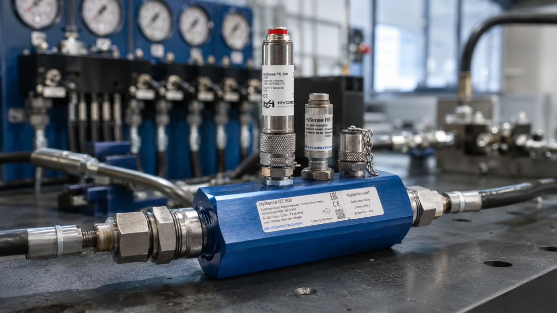
A suitable example is the HySense QT 600 measuring turbine flow sensor. It is designed for volume flow measurements with hydraulic media and is suitable for applications where fast signal response, pressure resistance, temperature or viscosity influences and reliable evaluation in the measuring system are important.
For a complete test bench, the measuring turbine should not be viewed in isolation. Pressure sensors, temperature sensors, speed sensors, data loggers or mobile measuring systems are often also required. Only the combined recording of several measured quantities makes it possible to reliably evaluate hydraulic processes.
When selecting a device, flow range, connection size, pressure range, medium, viscosity, temperature range, signal type, cable length and compatibility with the existing data acquisition system should be checked. Especially with hydraulic oil and changing temperatures, precise design is worthwhile so that the measured values in the test bench remain reliable.
Conclusion: Measuring turbines are strong when dynamics must become visible
Measuring turbines are particularly useful in test benches when volume flows need to be captured quickly and dynamically. They provide a fast signal, can be integrated well into data acquisition and help evaluate test cycles not only by final values, but by their time profile.
Especially in hydraulic test benches, temperature, viscosity, pressure, air in the system, dirt particles and installation conditions are decisive. Anyone who does not take these influencing factors into account will obtain measured values, but not necessarily reliable results.
Correctly designed and properly installed, a measuring turbine is a very effective measuring principle for pump test benches, valve testing, hydraulic tests, development and quality assurance. The greatest benefit arises when volume flow, pressure, temperature and other measured quantities are recorded together and evaluated in context.
FAQ: Frequently asked questions about measuring turbines in test benches
What is a measuring turbine?
A measuring turbine is a flow sensor in which a turbine wheel is driven by the medium. The rotational speed of the turbine wheel is electrically detected and used to calculate the volume flow.
Why is a measuring turbine suitable for test benches?
It is particularly suitable for test benches because it can capture rapid changes in volume flow. This makes load changes, valve switching operations, pump behavior and dynamic test cycles visible.
What does dynamic flow measurement mean?
Dynamic flow measurement means that the volume flow is considered over time. Not only a final value, but the entire profile during a test cycle is evaluated.
Which media can be measured with measuring turbines?
This depends on the design. In hydraulic test benches, measuring turbines are often used for hydraulic oils or other suitable oils. Media compatibility, viscosity and cleanliness must always be checked.
Why does viscosity influence the measurement?
Viscosity influences the flow behavior and thus also the behavior of the turbine. Especially with hydraulic oil, viscosity changes strongly with temperature.
Why should the oil temperature be documented?
The oil temperature influences viscosity. If the flow changes during a test cycle, the cause may lie in the test specimen, but also in the temperature change of the medium.
What is a frequency output?
A frequency output provides a signal whose frequency is proportional to the flow. The higher the volume flow, the higher the frequency.
What is the K-factor of a measuring turbine?
The K-factor describes the relationship between pulses and flow quantity. It is necessary so that the data acquisition system can calculate the correct volume flow from the sensor signal.
Why are inlet and outlet sections important?
They help achieve the most uniform possible flow profile at the measuring turbine. Strong disturbances directly upstream of the sensor can lead to unstable or deviating measured values.
Can air in the hydraulic system distort the measurement?
Yes. Air bubbles can lead to fluctuating or implausible measured values. The test section should therefore be filled slowly and carefully vented.
Why is clean hydraulic oil important?
Dirt particles can impair the turbine wheel, cause wear or distort the measurement. Suitable filtration and a clean test section are therefore important.
Can a measuring turbine measure pressure peaks?
A measuring turbine measures volume flow, not pressure. Pressure peaks should additionally be captured with a suitable pressure sensor or pressure measuring instrument.
When is a measuring turbine better than another flow meter?
A measuring turbine is particularly interesting when rapid volume flow changes need to be captured with clean, suitable media. For heavily contaminated, very viscous or unsuitable media, another measuring principle may be better.
How often should a measuring turbine be calibrated?
This depends on frequency of use, load, accuracy requirements and internal test equipment monitoring. In test benches with quality-relevant measurements, the calibration status should be monitored regularly.
Which measured quantities should also be captured in the test bench?
Pressure, temperature, speed, valve control signal, electrical power or switching states are often useful. Only the combination of several measured quantities enables a reliable assessment of the hydraulic system.