


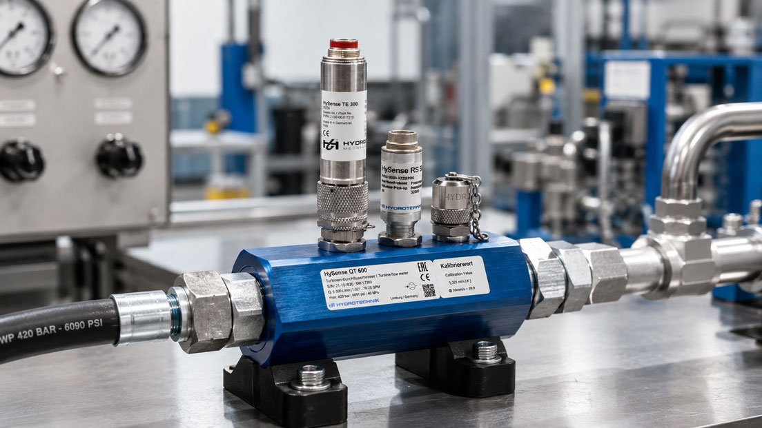
Turbine flowmeters are used in dosing, filling and test-bench systems when liquid volumes need to be recorded quickly and reproducibly. The sensor frequently provides a frequency or pulse signal that can be evaluated in two different ways.
The instantaneous volumetric flow rate can be calculated from the current pulse frequency. If, however, all pulses are counted during a dosing cycle, the total quantity dispensed is obtained directly. For batch and dosing processes, this totalisation is usually the decisive measured quantity.
A simple instantaneous-value display can show, for example, that 12 l/min is currently flowing. However, it does not directly indicate whether exactly 2.000 litres have actually reached the container at the end of the process. To determine this, the displayed flow rate would have to be integrated correctly over the complete dosing period.
This article explains how the K-factor, pulse counting, pre-shutoff and overrun quantity interact and which errors should be avoided when designing a dosing system with a turbine flowmeter.
Table of contents
- How a turbine flowmeter records volume
- Distinguishing frequency and pulse count
- The K-factor as the basis for totalisation
- Why pulse counting offers advantages for batch quantities
- Pulse resolution and minimum dosing quantity
- Considering pre-shutoff and overrun quantity
- Correctly selecting the valve, pump and dosing strategy
- Reliably recording pulses in the PLC
- Considering viscosity, temperature and medium
- Installation, venting and filtration
- Calibrating the K-factor and dosing system
- Testing pulse and frequency inputs
- Typical errors in dosing systems
- Practical example: Dosing two litres of hydraulic oil
- Which measuring instruments / products are suitable?
- Conclusion
- Frequently asked questions about dosing with turbine flowmeters
How a turbine flowmeter records volume
In a turbine flowmeter, the medium flows through a measuring channel and causes a turbine rotor to rotate. Within the intended measuring range, the rotor speed increases with the volumetric flow rate.
A magnetic, inductive or other suitable signal pickup detects the passing rotor blades and generates electrical pulses. Two measured quantities can be derived from this signal:
- The number of pulses per unit of time describes the instantaneous volumetric flow rate.
- The total number of pulses describes the volume that has flowed through the sensor.
For a process display, the instantaneous value in l/min is often of interest. For a dosing system, however, the total quantity per dosing cycle is decisive.
A turbine flowmeter measures volume rather than mass directly. If the density of the medium changes significantly with temperature, the same volume can correspond to different masses. If dosing in kilograms is required, the density must be taken into account or a direct mass-flow measuring principle must be used.
Distinguishing frequency and pulse count
Although frequency and pulse count originate from the same sensor signal, they fulfil different tasks.
| Evaluation | Calculation | Typical application |
|---|---|---|
| Frequency measurement | Pulses per second | Instantaneous flow rate in l/min |
| Pulse counting | Total number of pulses | Batch, filling or total quantity |
| Time integration of an analogue value | Sum of flow value × time | Determining quantity from a continuously measured value |
During frequency measurement, the number of pulses occurring within a defined time window is determined. The evaluation unit uses this value to calculate the current flow rate.
During totalisation, however, every valid pulse is added. The number of pulses counted since the start of the dosing cycle is then divided by the K-factor.
Pulse counting is not inherently more physically accurate than every other possible evaluation method. For batch dosing, however, it is often more direct and robust because the measured quantity does not first have to be calculated by numerically integrating numerous time-sampled instantaneous values.
The K-factor as the basis for totalisation
The K-factor specifies how many pulses the turbine flowmeter generates per unit of volume. Common units include:
- pulses per litre
- pulses per millilitre
- pulses per cubic metre
- pulses per gallon
The following applies when calculating the dosing quantity:
Volume = counted pulses ÷ K-factor
Example:
- K-factor: 1,000 pulses per litre
- counted pulses: 2,500
The recorded quantity is:
2,500 pulses ÷ 1,000 pulses/l = 2.5 l
When calculating the instantaneous flow rate from the frequency, the unit of time must also be considered. For a K-factor specified in pulses per litre, for example:
Flow rate in l/min = frequency in Hz × 60 ÷ K-factor
At 200 Hz and a K-factor of 1,000 pulses per litre, the result is:
200 × 60 ÷ 1,000 = 12 l/min
A frequent error is entering the correct numerical value with the wrong unit. If a K-factor in pulses per litre is mistakenly interpreted as pulses per cubic metre, the display and dosing quantity differ by a factor of 1,000.
Why pulse counting offers advantages for batch quantities
If a dosing quantity is calculated solely from an instantaneous value, the controller must sample the flow rate at short intervals and integrate it over the complete dosing period.
Additional deviations can be caused by:
- an excessively slow sampling rate for the instantaneous value
- filtering or averaging
- time delays in the analogue signal
- rounding of individual measured values
- different update intervals of the sensor and PLC
- changes during start-up and shutoff being missed
With pulse counting, however, every detected pulse is assigned to a defined partial volume. Even if the flow rate fluctuates during the batch process, the sum of the pulses still represents the total quantity.
This is advantageous, for example, when:
- a pump starts up gradually
- the pressure fluctuates during dosing
- the valve does not open instantaneously
- the system switches to a lower flow rate at the end of the batch
The prerequisite is that all pulses are detected reliably and that the configured K-factor matches the turbine flowmeter, medium and operating range.
Pulse resolution and minimum dosing quantity
Each pulse corresponds to a defined partial volume. This pulse value determines the theoretical resolution of the totalisation.
With a K-factor of 1,000 pulses per litre, one pulse corresponds to:
1 l ÷ 1,000 = 0.001 l = 1 ml
For a target quantity of two litres, approximately 2,000 pulses are counted. One pulse corresponds to 0.05% of the target quantity.
If, however, only 20 ml is to be dosed, only 20 pulses are available with the same K-factor. One pulse then already corresponds to 5% of the target quantity.
A sufficiently high K-factor is therefore required for small batch quantities. However, dosing resolution is not limited solely by the pulse value. Additional influences include:
- measuring deviation and repeatability of the turbine flowmeter
- starting behaviour of the rotor
- switching time of the valve
- overrun quantity
- droplet formation at the dosing nozzle
- air inclusions or compressible pipe sections
A high pulse count alone therefore does not guarantee a correspondingly high dosing accuracy.
Considering pre-shutoff and overrun quantity
If the dosing valve is actuated exactly when the target pulse count is reached, additional medium frequently continues to flow. The valve, pipe and pump do not react without delay.
The additional quantity flowing between the shutoff command and the actual end of flow is referred to as the overrun quantity. It can be caused by:
- closing time of the valve
- response time of the PLC and output module
- liquid between the valve and outlet nozzle
- pressure reduction in flexible pipes
- inertia of the pump
- height difference or hydrostatic pressure
Shutoff must therefore take place before the actual target value is reached:
Pre-shutoff quantity = target quantity − expected overrun quantity
If 5.000 litres are to be filled and the typical overrun is 0.080 litres, the valve closure is initially triggered at 4.920 litres.
The overrun quantity is not always constant. It can change with pressure, flow rate, temperature, viscosity and the level in the supply tank. For applications with high accuracy requirements, the controller can automatically correct the shutoff point based on previous batches.
Correctly selecting the valve, pump and dosing strategy
Dosing accuracy is not determined by the flowmeter alone. The valve and pump are essential parts of the complete dosing chain.
Single-stage dosing
In a simple dosing process, the complete operation runs at a fixed flow rate. The valve is closed shortly before the target value is reached.
This method is simple but sensitive to changes in the overrun quantity. The higher the flow rate, the greater the quantity that usually continues to flow during the valve closing time.
Two-stage dosing
During coarse/fine dosing, most of the quantity is filled at a high flow rate. Shortly before the target value is reached, the system switches to a lower flow rate.
The lower final flow rate reduces the overrun quantity and makes precise shutoff easier. This can be implemented using, for example:
- two valves of different sizes
- a two-stage valve
- a variable-speed pump
- a bypass or throttling stage
The switching points must be selected so that the process remains stable and the turbine flowmeter continues to operate above its minimum flow rate during fine dosing.
Reliably recording pulses in the PLC
The pulses from the turbine flowmeter must be evaluated by a suitable digital counter or frequency input. A conventional digital input that is scanned slowly may miss pulses at higher frequencies.
The following must therefore be checked before commissioning:
- maximum output frequency of the turbine flowmeter
- permissible input frequency of the PLC module
- signal type, such as push-pull, open collector or NAMUR
- signal level and supply voltage
- minimum pulse width
- input filter and debounce time
- counter overflow and numerical format
The maximum frequency occurs at the highest intended flow rate. It can be calculated from the K-factor and volumetric flow rate:
Frequency in Hz = flow rate in l/min × K-factor ÷ 60
At 60 l/min and 1,000 pulses per litre, the following frequency is generated:
60 × 1,000 ÷ 60 = 1,000 Hz
The counter input used must be capable of processing this frequency reliably and with sufficient reserve.
The counter should be reset in a controlled manner at the start of every batch. At the same time, it must be ensured that pulses from the overrun of a previous batch or from draining the pipe are not transferred to the next batch.
Considering viscosity, temperature and medium
The K-factor of a turbine flowmeter is not completely constant under all conditions. In particular, viscosity influences the relationship between rotor movement and actual volumetric flow rate.
As viscosity increases, frictional and flow-related influences also increase. Especially in the lower measuring range, the turbine may therefore generate fewer pulses than during calibration with a lower-viscosity medium.
For accurate dosing, the following should therefore be known:
- medium and composition
- minimum and maximum viscosity
- operating temperature
- density, if the dosing quantity is evaluated as mass
- solids or particle content
- chemical compatibility of the housing, bearings and seals
If the viscosity changes significantly, calibration with several K-factors or temperature-dependent correction may be required.
For highly viscous media, liquids containing solids or very small dosing quantities, a gear or oval-gear meter may be more suitable. For conductive liquids and applications requiring no moving parts, an electromagnetic flowmeter may be suitable depending on the process.
Installation, venting and filtration
A turbine flowmeter should be operated completely filled with medium and free of gas bubbles. Air or gas in the liquid flow is recorded by the sensor as additional displaced volume and can significantly distort the dosing quantity.
Typical causes of air inclusions include:
- insufficiently vented pipes
- leaking suction pipes
- insufficient inlet pressure
- cavitation at the pump or valve
- emptying supply tanks
- unfavourable pipe routing with high points
Particles can also affect the rotor and bearings. Suitable filtration protects the turbine flowmeter but must not cause an impermissible pressure loss or cavitation.
The following must also be considered during mechanical installation:
- specified direction of flow
- sufficient inlet and outlet pipe lengths
- stress-free installation in the pipe
- no strongly disturbing fittings directly upstream of the sensor
- completely filled measuring cross-section
- suitable grounding and shielding of the signal cable
The specific installation conditions must be taken from the data sheet of the respective turbine flowmeter.
Calibrating the K-factor and dosing system
The individual K-factor from the sensor calibration certificate should be used for evaluation. A general nominal value is frequently insufficient for precise dosing applications.
During multipoint calibration, K-factors are determined at different flow rates. The evaluation unit can use these values to create a characteristic curve or apply correction in sections.
However, sensor calibration alone does not cover all influences of the actual dosing system. The complete system should additionally be tested using a reference quantity, for example by:
- gravimetric checking on a suitable scale
- comparison with a calibrated reference vessel
- comparison with a suitable reference flowmeter
During gravimetric testing, the mass must be converted into volume using the density if the dosing controller operates in litres. Temperature-dependent density changes must be taken into account.
In addition to the sensor, the system test also covers the valve response, overrun, pipe contents and control logic. This complete test is therefore particularly meaningful when approving the dosing accuracy.
Testing pulse and frequency inputs
If a dosing system displays incorrect quantities, a distinction must be made between a mechanical sensor problem and an error in the electrical evaluation.
Using a frequency or pulse simulator, defined signals can be applied to the PLC or batch-counter input. This makes it possible to check:
- whether every pulse is detected
- whether the K-factor is configured correctly
- whether litres and cubic metres are assigned correctly
- whether the counter switches at the target value
- whether the pre-shutoff and alarm limits function correctly
- whether high frequencies are processed without pulse loss
If, for example, 2,000 defined pulses are supplied and only 0.2 litres are displayed with a K-factor of 1,000 pulses per litre, the error is probably in the scaling or unit rather than in the turbine flowmeter.
However, electrical simulation does not test the rotor, bearings or actual flow characteristic. After the signal test, the sensor must therefore be checked with real flow if necessary.
Typical errors in dosing systems
| Fault symptom | Possible cause | Better approach |
|---|---|---|
| Batch quantity is always too high | Overrun quantity is not taken into account | Determine and correct the pre-shutoff point |
| Deviation increases with small batches | Pulse count too low or overrun too high | Use a higher K-factor or a fine-dosing stage |
| Quantity fluctuates from batch to batch | Air bubbles, pressure changes or varying valve response | Vent the process and stabilise the dosing conditions |
| Displayed quantity differs by a factor of 1,000 | K-factor configured using the wrong volume unit | Check pulses per litre or cubic metre |
| Too few pulses are counted at a high flow rate | Input frequency exceeded or pulses too short | Use a fast hardware counter and suitable input circuitry |
| Too little is indicated at a low flow rate | Turbine flowmeter is below its minimum flow rate or viscosity is too high | Adapt the measuring range and calibration conditions |
| Target quantity is electrically correct but not in the vessel | Leakage, dripping loss or medium remains in the pipe | Check the complete dosing section gravimetrically |
Practical example: Dosing two litres of hydraulic oil
In a test bench, 2.000 litres of hydraulic oil are to be dosed into a measuring vessel during every cycle. The turbine flowmeter has a calibrated K-factor of 1,250 pulses per litre.
The number of pulses required for the target quantity is:
2.000 l × 1,250 pulses/l = 2,500 pulses
With the initial configuration, the valve is closed when 2,500 pulses are reached. However, the gravimetric check produces an average result of 2.065 litres.
The system therefore doses approximately 65 ml too much. The cause is the overrun quantity during the valve closing time.
At this K-factor, 65 ml corresponds to:
0.065 l × 1,250 pulses/l = approximately 81 pulses
The pre-shutoff point is initially set to:
2,500 − 81 = 2,419 pulses
Several repeat measurements subsequently produce quantities between 1.996 and 2.004 litres.
To further improve repeatability, the pump flow rate is reduced shortly before the target value is reached. This decreases the overrun quantity and makes it less sensitive to pressure fluctuations.
The PLC counter input is also tested using a pulse simulator. The controller detects all pulses correctly and switches reproducibly at the configured pre-shutoff point.
The example shows that not only the K-factor but also the dynamic response of the complete dosing system must be considered.
Which measuring instruments / products are suitable?
Turbine flowmeters for dosing, filling and test benches
The turbine flowmeters category contains different turbine flow sensors for clean liquids and, depending on the model, also for gases.
When designing a dosing measuring point, the medium, viscosity, flow range, temperature, pressure, required K-factor and output signal must be specified in particular.
HySense QT4xx for robust flow measurements
The HySense QT4xx heavy-duty high-precision turbine flow sensor is a robust version with low flow resistance.
Depending on the version, frequency, analogue or CAN signals are available. For a dosing application, the frequency-output version is particularly relevant, provided that the measuring range, medium and calibration are suitable for the application.
HySense QT5xx for precise volumetric-flow measurements
The HySense QT5xx turbine flow sensor is suitable for precise volumetric-flow measurements in stationary and mobile fluid systems.
Its specific suitability for a dosing system depends on the liquid, viscosity, required minimum quantity and required pulse resolution. ICS Schneider Messtechnik assists with selecting the correct size and calibration.
MultiSystem 5070 for pulse counting and process analysis
The MultiSystem 5070 has switchable frequency and pulse inputs with a counter function and direction detection.
This enables the pulse signals from a turbine flowmeter to be recorded and counted together with additional quantities such as pressure and temperature. This is particularly useful during commissioning, test-bench analysis and troubleshooting.
CPH8000 for testing counter and PLC inputs
In addition to other electrical quantities, the WIKA CPH8000 portable multifunction calibrator can also measure and simulate frequencies and pulses.
This allows counters, displays and PLC inputs to be tested independently of the turbine flowmeter. The simulator can output defined pulse counts and thereby check the K-factor, quantity scaling and shutoff logic.
Further instruments for the targeted simulation of electrical sensor signals can be found in the simulators and signal generators category.
ICS Schneider Messtechnik assists with selecting the turbine flowmeter, evaluation electronics, K-factor, counter input and calibration method. The required information includes the medium, viscosity and temperature range, minimum and maximum dosing quantity, required dosing time, process pressure, connection size and required accuracy.
Conclusion: Pulses must be counted to determine the dosing quantity
The instantaneous flow rate indicates how quickly the medium is currently flowing through the pipe. For a batch or filling system, however, the total quantity that has flowed during the complete cycle is decisive.
Pulse counting adds every partial volume detected by the sensor. The batch quantity is obtained directly from the pulse count and K-factor. Fluctuations in the instantaneous flow rate are automatically included in the total quantity.
Nevertheless, dosing accuracy does not depend solely on the turbine flowmeter. Pulse resolution, minimum flow rate, viscosity, valve closing time, overrun quantity, venting and the PLC counter input must be considered together.
For small batch quantities or demanding requirements, coarse/fine dosing is often useful. The shutoff point is positioned before the target quantity is reached so that the quantity continuing to flow after the switching command is taken into account.
Testing with a frequency and pulse simulator separates faults in the electrical evaluation from mechanical problems with the turbine flowmeter. However, the final dosing accuracy should always be checked using a suitable real reference quantity.
Frequently asked questions about dosing with turbine flowmeters
Why is the pulse count used for a batch quantity?
The pulse count is directly proportional to the total volume. The instantaneous flow rate, however, describes only the current operating condition and would have to be integrated over time.
What does the K-factor of a turbine flowmeter mean?
The K-factor specifies how many pulses the sensor generates per unit of volume, for example pulses per litre.
How is the dosing quantity calculated?
The counted pulse number is divided by the K-factor. With 2,000 pulses and 1,000 pulses per litre, the quantity is two litres.
Why does the system dose too much despite the correct pulse count?
Medium may continue to flow after the shutoff command. This overrun quantity must be taken into account by using a pre-shutoff point.
How small can a batch quantity be?
This depends on the K-factor, minimum flow rate, rotor start-up, valve response and overrun quantity. A different measuring principle may be more suitable for very small quantities.
Can every PLC digital input count the pulses?
No. The input must be suitable for the maximum frequency and pulse width. A special high-speed counter or frequency input is frequently required.
How do air bubbles affect the measurement?
Gas bubbles displace liquid and can cause additional rotor movement. The counted quantity then no longer corresponds to the liquid quantity actually dispensed.
When must the K-factor be redetermined?
A check is particularly advisable after a repair, noticeable drift, a change of medium, significantly changed viscosity or high mechanical loads.
Can the PLC evaluation be tested without actual flow?
Yes. Defined signals can be supplied using a pulse or frequency simulator to test the quantity scaling, counter function and shutoff logic.
Which information does ICS Schneider require for system design?
The required information includes the medium, viscosity, temperature, pressure, flow range, smallest and largest batch quantity, required dosing time, process connection, output signal and required accuracy.