


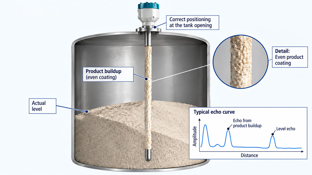
A TDR level transmitter monitors the contents of an industrial storage tank. The measuring point operates reliably for several months. However, as operating time increases, deposits begin to form on the metallic measuring probe. Initially, the level indication remains plausible. Later, occasional measurement jumps occur until the instrument suddenly indicates an almost constant level while the tank is being emptied.
During an inspection, it is found that a uniform product layer has formed on part of the probe. Near an internal tank component, there is also a larger accumulation of material connecting the probe to a metallic support.
Which of these deposits causes the measurement deviation? Why does the probe initially continue operating despite a uniform coating, while localized bridging can cause significant errors? And can the difference be identified from the instrument’s echo curve?
Such questions arise in the chemical industry, tank installations, the processing of viscous liquids, and silos and vessels containing bulk solids that tend to adhere to surfaces.
TDR level measurement, also known as guided wave radar or guided microwave measurement, uses electromagnetic pulses guided along a metallic probe. Reflections occur where the electrical properties change along the measurement path. The instrument determines the distance to the product surface from the transit time of the corresponding level echo.
Because the probe is in direct contact with the process medium, product deposits can alter its electrical and mechanical properties. However, the effects depend significantly on the shape, distribution, and electrical characteristics of the buildup.
A thin, uniform coating along the probe can change the propagation conditions and attenuate the useful signal. Depending on the measuring system, probe type, and medium, the level measurement may nevertheless continue to operate reliably.
Localized bridging must be evaluated differently. If an electrically conductive or strongly dielectric product accumulation connects the probe to a metallic internal component, pronounced reflections or other signal disturbances may occur. With coaxial probes, bridging between the inner conductor and outer tube is particularly problematic.
As a result, the instrument may incorrectly assign an echo, temporarily lose the level signal, or output a substitute or fault value depending on its configuration.
Another challenge is distinguishing an actual increase in level from an apparent level change caused by growing deposits. Measurement deviations can remain unnoticed for a long time, particularly when buildup develops gradually.
This technical article explains the physical differences between uniform coating, localized product buildup, and bridging on TDR probes. It describes how these conditions may appear in the echo curve and explains the importance of probe design, vessel geometry, dielectric constant, and parameterization.
A detailed calculation example illustrates how a product bridge can cause an apparently excessive level reading and a corresponding incorrect 4-to-20-mA signal. Installation, cleaning, false echo suppression, diagnostics, alarming, and suitable instruments from the ICS product range are also covered.
Table of Contents
- Measurement Task and Typical Problems Caused by Product Deposits
- Operating Principle of TDR Level Measurement
- Correctly Evaluating Uniform Coating on the Probe
- Distinguishing Bridging from Localized Deposits
- Considering Medium Properties, Dielectric Constant, and Buildup Formation
- Selecting Rod, Cable, and Coaxial Probes Correctly
- Evaluating Vessel Geometry, Nozzles, and Internal Components
- Practical Example: Calculating Product Bridging, Level Errors, and Output Signals
- Systematically Evaluating Echo Curves and Echo Assignment
- Signal Attenuation, Additional Reflections, and Echo Loss
- Product Buildup with Liquids and Viscous Media
- Deposits and Bridging in Bulk Solids
- Influence of Product Buildup on Interface Measurement
- Considering Probe Ends, Near Zones, and Dead Zones
- Using False Echo Suppression and Automatic Diagnostics Correctly
- Checking Parameterization, Measuring Range, and Output Signals
- Probe Cleaning and Preventive Maintenance
- Evaluating Measurement Uncertainty and Gradual Measurement Deviations
- Process Safety, Overfill Protection, and Explosion Protection
- Systematic Testing and Commissioning Procedure
- Typical Fault Symptoms and Targeted Diagnostics
- Suitable ICS Products for Challenging Level Measurement Applications
- Conclusion: Product Coating Is Not the Same as Bridging
- Frequently Asked Questions About TDR Probes with Product Buildup
1. Measurement Task and Typical Problems Caused by Product Deposits
In continuous level measurement, the instrument is intended to reliably determine the actual position of the product surface.
The measurement must also function under changing operating conditions. These include filling, emptying, temperature changes, pressure fluctuations, and possible changes in the composition of the medium.
With product-contacting TDR probes, an additional factor must be considered: the process medium can adhere to the metallic or coated probe.
1.1 Typical Causes of Product Buildup
Deposits can form for various reasons:
- High viscosity of the process medium.
- Cooling and solidification on the probe.
- Crystallization of dissolved substances.
- Drying after partial emptying of the vessel.
- Deposition of solid particles.
- Polymerization or chemical reactions.
- Adhesive bulk solids or powdered products.
- Sludge and sediment formation.
Which of these causes is relevant depends on the medium, temperature, process operation, and material properties.
1.2 Not Every Deposit Immediately Causes an Error
A thin, uniform product layer does not necessarily prevent level measurement immediately.
Some TDR systems have signal processing functions that can reduce certain effects of product deposits.
However, increasing or uneven buildup can produce additional reflections and reduce the available signal margin.
1.3 Different Fault Symptoms
Product deposits can manifest themselves through:
- Gradually increasing measurement deviations.
- Unstable level indications.
- Sudden switching between two level values.
- A level signal that remains constant during emptying.
- Apparent overfilling.
- Progressively weaker useful signals or level echoes.
- Loss of the valid level echo.
- Diagnostic messages or a configured fault output.
None of these symptoms alone proves that product buildup is the cause.
Incorrect parameterization, internal vessel components, changing medium conditions, or electrical problems can cause similar symptoms.
1.4 Objective of the Diagnosis
The diagnosis should determine whether the probe is merely coated, whether a pronounced localized deposit is present, or whether an actual bridge has formed between conductive or otherwise acoustically or electromagnetically relevant structures.
The echo curve, time-dependent measurement profile, knowledge of the process, and, where appropriate, a safe physical inspection are decisive for this evaluation.
2. Operating Principle of TDR Level Measurement
TDR stands for Time Domain Reflectometry.
In level measurement, the method is also referred to as guided radar or guided microwave measurement.
2.1 Electromagnetic Pulse
The transmitter sends an electromagnetic pulse along a suitable probe.
The probe may be designed as a rod, cable, or coaxial conductor arrangement.
The pulse is guided along this structure.
2.2 Reflection at the Product Surface
At the product surface, the electromagnetic properties of the surrounding medium change.
This change causes part of the guided signal to be reflected.
The strength of the reflection depends, among other factors, on the electrical properties of the medium and the probe configuration.
2.3 Transit-Time Measurement
The transmitter measures the transit time of the reflected pulse.
In simplified form:
d = veff · t / 2
Where:
- d is the distance to the reflecting point.
- veff is the effective propagation velocity along the measurement path being considered.
- t is the round-trip transit time of the signal.
The actual evaluation takes the probe design, reference point, and device-specific signal processing into account.
2.4 Conversion into Level
For simple vessel geometry, the level can be determined from the known reference height and measured distance:
h = H – d
Here, H represents the distance between the defined upper reference point and the lower level reference point.
This equation assumes that the measurement geometry has been defined accordingly.
2.5 Why Deposits Matter
The electromagnetic wave does not respond exclusively to the actual product surface.
Other changes in electrical properties along the measurement path can also produce reflections or attenuation.
These include localized product accumulation, bridging to a metallic internal component, and changes in the environment surrounding the probe.
The measurement task therefore involves reliably distinguishing the correct level echo from other reflections.
3. Correctly Evaluating Uniform Coating on the Probe
Uniform product buildup occurs when a section of the probe is covered by a largely continuous product layer over a certain length.
The layer may be thin or thick, dry or wet, electrically conductive or non-conductive.
3.1 Effect of a Thin Layer
A thin layer can change the electromagnetic properties of the immediate environment surrounding the probe.
As a result, the signal shape, propagation conditions, and amplitude of the reflected level echo may be affected.
However, a single additional strong reflection does not necessarily occur.
3.2 Uniform and Gradual Changes
If a deposit develops uniformly over an extended period, the echo curve may change gradually.
A suitable measuring system may continue to process certain changes of this kind.
However, the magnitude of any remaining measurement error depends on the coating, probe type, and signal processing method.
3.3 Electrically Conductive Coating
An electrically conductive layer can influence the electromagnetic field along the probe more strongly than a thin layer with a low dielectric constant.
The actual effect depends on conductivity, layer thickness, continuity, and any connections to other conductive structures.
An electrically conductive coating is therefore not automatically harmless.
3.4 Non-Conductive Coating
A non-conductive layer can also affect the measurement.
For example, it may change the local effective permittivity and thereby influence wave propagation.
The extent of the deviation depends on the specific material properties and geometry.
3.5 Critical Transitions
Particularly important locations may be those where a coating begins or ends, or where its thickness changes abruptly.
These points produce greater changes in the electrical environment than a largely continuous layer.
Such transitions can cause additional reflections.
3.6 No Universal Buildup Tolerance
There is no universally applicable layer thickness for all TDR probes below which every deposit is guaranteed to cause no measurement error.
Suitability must be evaluated based on the specific product, probe design, manufacturer specifications, and actual buildup formation.
4. Distinguishing Bridging from Localized Deposits
Bridging occurs when an accumulation of product creates a connection between areas that are normally separated.
For TDR probes, bridges between the probe and the metallic vessel wall, between the probe and internal components, and between the inner conductor and outer tube of a coaxial probe are particularly relevant.
4.1 Bridging to the Vessel Wall
A rod or cable probe may be positioned near a metallic vessel wall or internal component.
If adhering product forms a continuous bridge at this location, the local electromagnetic conditions change significantly.
This can produce a pronounced false echo.
4.2 Bridging in a Coaxial Probe
A coaxial probe has an inner conductor and a surrounding outer conductor structure.
The space between them is intended for wave propagation.
If adhering product accumulates in this space and forms a bridge, propagation can be significantly affected.
This can be particularly problematic with electrically conductive media.
4.3 Localized Deposits
Even without a complete connection to a vessel wall, a thick localized product accumulation can represent a significant interference point.
The abrupt change in electrical properties can generate an additional echo pulse.
4.4 Why an Excessively High Level May Be Indicated
If a localized product accumulation is located above the actual product surface, the reflection generated there may reach the transmitter earlier than the true level echo.
If this reflection is incorrectly interpreted as the product surface, the instrument calculates a shorter distance and therefore a higher level.
This is one possible fault symptom, but it is not the universal response of all TDR instruments.
4.5 Other Possible Responses
Depending on signal processing, bridging can also result in a weaker useful signal, measurement jumps, echo loss, or a configured fault condition.
A specific level error therefore cannot be predicted solely from the geometric position of a bridge.
| Type of Deposit | Typical Geometry | Possible Measurement Effect | Diagnostic Approach |
|---|---|---|---|
| Thin, uniform coating | Largely continuous film along the probe | Changed signal shape, transit time, or signal margin; measurement may continue functioning | Compare echo curve and signal quality over time |
| Thick, uniform coating | Greater layer thickness over a longer probe section | Stronger attenuation or altered electromagnetic propagation | Check medium properties and manufacturer’s buildup tolerance |
| Localized product accumulation | Limited area with significantly altered cross-section | Additional echo or changed echo assignment | Compare reflection position with vessel geometry |
| Bridge to vessel wall | Product connects the probe to the metallic wall | Significantly altered electrical environment; false echo or signal loss possible | Check installation clearances, echo position, and buildup formation |
| Bridge in a coaxial probe | Product connects the inner conductor and outer tube | Significant disturbance of wave propagation and potentially incorrect level readings | Examine the coaxial gap and product deposits |
| Deposit at probe end | Accumulation at the probe tip or end weight | Changed probe-end echo and potentially impaired end detection | Check probe length, end echo, and lower measuring range |
| Deposit at process connection | Product accumulation in the nozzle or near zone | Strong near-zone echo or reduced signal margin | Check nozzle geometry, near zone, and false echo suppression |
The table illustrates typical effects rather than a universally applicable relationship between deposit geometry and a fixed measurement error.
The actual response must be examined on the specific measuring system.
5. Considering Medium Properties, Dielectric Constant, and Buildup Formation
The electrical properties of the medium play an essential role in the formation and strength of reflections.
5.1 Relative Permittivity
Relative permittivity, commonly referred to as the dielectric constant εr, describes an important electrical property of the medium.
A difference between the electrical environment above the product surface and the product itself causes a reflected signal to form.
5.2 Low Dielectric Constant
With media having a low dielectric constant, the level echo may be comparatively weak.
Additional deposits and false reflections can then become particularly significant.
The suitable minimum dielectric constant depends on the specific probe and instrument configuration.
5.3 High Dielectric Constant
Media with higher dielectric constants can produce pronounced reflections under suitable conditions.
This can make level detection easier.
However, corresponding deposits above the actual level may also generate strong localized reflections.
5.4 Electrical Conductivity
With conductive media, bridging requires particular attention when it connects conductive parts of the probe and vessel structure.
The precise effect depends on electrical conductivity, the cross-section of the deposit, and geometry.
5.5 Viscosity and Flow Behavior
Highly viscous media can remain attached to the probe after the vessel is emptied.
Whether the deposit drains uniformly or accumulates at certain locations depends on viscosity, surface wetting, temperature, and probe geometry.
5.6 Crystallization and Solidification
Crystallizing or solidifying media can form permanent layers.
Pronounced product accumulations may develop particularly at geometric transitions, supports, or narrow gaps around the probe.
These areas should already be considered when selecting the probe design.
6. Selecting Rod, Cable, and Coaxial Probes Correctly
The design of a TDR probe influences both the electromagnetic field geometry, rather than any acoustic propagation, and its mechanical tendency to accumulate deposits.
Rod, cable, and coaxial probes have different advantages and limitations.
6.1 Rod Probes
Rod probes consist of a relatively rigid conductor, usually made of metal.
They are frequently used in liquid vessels and for shorter measuring ranges.
Because of their comparatively simple external geometry, they may be more suitable for certain adhesive media than closely spaced coaxial probes.
However, sufficient clearance from internal vessel components must be maintained.
6.2 Cable Probes
Cable probes consist of a flexible metallic measuring conductor.
They are particularly suitable for longer measuring ranges and corresponding bulk solid or liquid applications.
With moving media, bulk solids, and agitators, possible deflection and tensile loads must be considered.
Sufficient clearance from metallic vessel components is important to prevent impermissible contact conditions caused by product deposits or mechanical movement.
6.3 Coaxial Probes
Coaxial probes guide the electromagnetic field between an inner conductor and a surrounding outer conductor.
Under certain installation conditions, this can make the measurement less sensitive to nearby internal vessel components.
However, the narrow space between the inner and outer conductors can be a disadvantage with strongly adhesive media.
Product accumulations can partially or completely bridge this space.
6.4 Suitable Probe Coatings
Suitable coated probes are available for certain aggressive or adhesive media.
A coating can improve chemical resistance and may reduce adhesion under certain conditions.
However, it does not guarantee that deposits will be completely prevented.
Approval must apply to the specific probe design and medium.
6.5 Selection According to Buildup Tendency
If significant product buildup is expected, probe design and the possibility of bridging should be evaluated before ordering.
In certain cases, a single rod or cable probe may be more suitable than a coaxial probe.
The final selection also depends on measuring length, vessel geometry, dielectric constant, and process conditions.
7. Evaluating Vessel Geometry, Nozzles, and Internal Components
Vessel geometry can significantly influence the formation and effects of product deposits.
7.1 Distance from the Vessel Wall
For rod or cable probes, the required clearance from metallic walls and internal components must be maintained.
Insufficient clearance can encourage additional reflections and increase the risk of product bridging.
The required minimum distances depend on the device and application.
7.2 Internal Components
Ladders, pipes, braces, agitators, and other internal vessel components may be located near the probe.
They can influence the electromagnetic field and may provide locations where bridging begins when adhesive products are present.
7.3 Filling Stream
A sensor should not be mounted directly in an area with heavy product inflow without evaluating the conditions.
Filling streams can mechanically load the probe and encourage localized product deposits.
7.4 Mounting Nozzles
When installing through a vessel nozzle, its height, diameter, and the probe position must be considered.
Unfavorable nozzle geometry can cause additional signal influences in the near zone.
Product deposits inside the nozzle can intensify these effects.
7.5 Centering and Support
Centering or support elements may be necessary for certain probe lengths or vessel geometries.
Such components must be suitable for the particular probe configuration.
At the same time, it must be checked whether product can accumulate on them and form a problematic bridge.
7.6 Movable Probes
A cable probe can be deflected by flow, agitators, or bulk solid movement.
The installation must prevent impermissible contact with vessel walls or internal components.
Subsequent mechanical fixing is only permissible if approved for the specific probe.
8. Practical Example: Calculating Product Bridging, Level Errors, and Output Signals
An industrial liquid vessel is monitored using a TDR rod probe.
During emptying, a localized product bridge forms between the probe and a metallic internal component above the actual product surface.
In the following simplified example, it is assumed that the instrument incorrectly interprets the resulting reflection as the level echo.
The aim is to calculate the effect on the indicated level and analog output signal.
8.1 Initial Data and Assumptions
The following freely selected values are explicitly used:
- Measuring range: 0 to 4.00 m level.
- Upper measuring reference point: 4.00 m above the lower reference point.
- Actual level: 1.40 m.
- Localized product bridge: 1.80 m below the upper reference point.
- Instrument evaluation: In the fault condition, the bridge reflection is selected as the valid level echo.
- Analog output: 4 to 20 mA.
- Scaling: 4 mA at 0 m and 20 mA at 4.00 m level.
- Linear relationship between calculated level and output current.
- No additional volume linearization.
These values describe a hypothetical fault condition and not a guaranteed response of any particular SITRANS LG configuration.
8.2 Calculate the Actual Distance to the Product Surface
The upper reference point is located 4.00 m above the lower level reference point.
The actual level is 1.40 m.
The distance is therefore:
dactual = H – hactual
dactual = 4.00 m – 1.40 m
dactual = 2.60 m
8.3 Distance to the Product Bridge
According to the selected assumptions, the product bridge is located 1.80 m below the upper measuring reference point.
dbridge = 1.80 m
It is therefore positioned above the actual product surface.
8.4 Calculate the Incorrectly Indicated Level
If the echo from the product bridge is mistakenly interpreted as the product surface:
hindicated = H – dbridge
hindicated = 4.00 m – 1.80 m
hindicated = 2.20 m
In this simplified fault scenario, the instrument would indicate a level of 2.20 m.
8.5 Absolute Level Deviation
The difference between the indicated and actual level is:
Δh = hindicated – hactual
Δh = 2.20 m – 1.40 m
Δh = +0.80 m
The indicated level is therefore 0.80 m, or 800 mm, above the actual value.
8.6 Relative Deviation Based on Measuring Range
For the considered measuring range of 4.00 m:
εrange = Δh / H · 100 %
εrange = 0.80 m / 4.00 m · 100 %
εrange = +20 %
The level deviation corresponds to 20 % of the configured measuring span.
This is a relative deviation in the calculation example, not a product-specific accuracy specification.
8.7 Correct Analog Output Signal
For linear scaling of 0 to 4.00 m to 4 to 20 mA:
I = 4 mA + 16 mA · h / H
At the actual level of 1.40 m:
Icorrect = 4 mA + 16 mA · 1.40 / 4.00
Icorrect = 9.60 mA
8.8 Incorrect Analog Output Signal
At the incorrectly determined level of 2.20 m:
Iincorrect = 4 mA + 16 mA · 2.20 / 4.00
Iincorrect = 12.80 mA
The current signal deviation is:
ΔI = 12.80 mA – 9.60 mA
ΔI = +3.20 mA
Incorrect echo assignment can therefore result in an analog signal that appears electrically completely plausible.
The receiver of the 4-to-20-mA loop cannot necessarily recognize from the current value alone that the underlying level measurement is incorrect.
| Parameter | Actual Product Surface | Incorrectly Evaluated Product Bridge |
|---|---|---|
| Measuring reference height | 4.00 m | 4.00 m |
| Distance from upper reference point | 2.60 m | 1.80 m |
| Calculated level | 1.40 m | 2.20 m |
| Level as percentage of measuring span | 35 % | 55 % |
| Output signal at 4 to 20 mA | 9.60 mA | 12.80 mA |
| Absolute level deviation | Reference | +0.80 m |
| Relative deviation based on measuring span | Reference | +20 % |
| Difference in current signal | Reference | +3.20 mA |
| Cause | Reflection from the actual product surface | Reflection from a localized product accumulation is incorrectly assigned |
8.9 Fault Behavior During Emptying
If the product bridge remains in the same position and the instrument continues to select its echo, the indicated level may remain nearly constant.
Meanwhile, the actual level continues to decrease.
This can produce an unusual plateau in the measurement trend.
Such a plateau is a possible indication of a fixed false reflection, but it does not prove bridging by itself.
8.10 Fault Behavior After Removing the Deposit
If the bridge is safely removed and the actual level echo is once again correctly evaluated, the indicated value may jump back to the real level.
The magnitude of such a jump depends on the actual level at that time.
The event should be documented and, if necessary, verified using an independent level reference.
8.11 Limitations of the Calculation Example
The example explicitly assumes that the instrument selects the bridge reflection as the valid level echo.
An actual TDR instrument may respond differently depending on signal processing, false echo suppression, and fault settings.
For example, it may continue to recognize the actual level echo, report echo loss, or output a substitute value.
The calculation example therefore illustrates a possible error mechanism rather than the guaranteed behavior of every TDR measuring instrument.
9. Systematically Evaluating Echo Curves and Echo Assignment
The echo curve is one of the most important diagnostic tools in TDR level measurement.
It displays the reflections detected by the measuring system along the measurement range being considered.
9.1 Product Surface Echo
The actual level echo is generated at the electromagnetically effective boundary between the environment above the product surface and the medium.
The position of the echo is related to the distance to the product surface.
9.2 Echoes from Internal Vessel Components
Internal components, process connections, or other geometric and electrical discontinuities can cause additional reflections.
Certain false echoes may already be present during commissioning.
9.3 Newly Appearing Echo
If a localized product accumulation develops, the echo curve may show an additional signal at a previously unremarkable position.
A comparison with an earlier echo curve recorded under known process conditions is particularly informative.
9.4 Uniform Coating
A largely uniform coating can change the signal shape and propagation conditions without necessarily generating a single dominant false echo.
Evaluation must therefore consider not only the number of echoes but also their amplitude and development over time.
9.5 Distinguishing Level Echoes from False Echoes
When the level changes, a genuine level echo generally follows the actual product surface.
A fixed product bridge at an unchanged position, on the other hand, may produce a stationary false echo.
Comparing level changes with echo positions is therefore an important diagnostic approach.
9.6 Avoid Overinterpreting the Echo Curve
Not every new reflection is a product bridge.
Changes in medium composition, vessel conditions, or parameterization can also influence the echo curve.
Diagnostics must therefore be compared with the actual process information.
10. Signal Attenuation, Additional Reflections, and Echo Loss
Product deposits can have different electrical effects on TDR measurement.
The most important phenomena are signal attenuation, additional reflections, and loss of clear echo assignment.
10.1 Signal Attenuation
Changes in the electromagnetic environment or the presence of lossy materials can reduce signal strength.
A weaker level echo is particularly critical when only a limited signal margin is available.
10.2 Additional Reflection
A localized change in electrical properties can generate an additional reflection.
This may occur, for example, at a pronounced product accumulation or bridge.
10.3 Overlapping Echoes
When different reflecting points are close together, their signals may interact during evaluation.
This can make it more difficult to identify the actual level echo unambiguously.
10.4 Echo Loss
Under unfavorable conditions, the actual level echo may no longer be detected adequately.
The instrument then responds according to its diagnostic and fault settings.
A valid level must not be assumed merely because a numerical value continues to be displayed.
10.5 Changing Deposits
If a product accumulation grows or partially detaches, the false reflection may change over time.
This can cause sudden changes in the measured value.
10.6 Evaluation Using Process Data
An unusual measurement trend should be compared with filling and emptying operations, pump status, temperatures, and any other available level information.
A sudden measurement change without a corresponding process change indicates a measurement or signal condition that requires investigation.
11. Product Buildup with Liquids and Viscous Media
In liquid applications, the type of deposit depends primarily on viscosity, wetting behavior, temperature, and chemical properties.
11.1 Thin Liquid Films
After emptying, a thin liquid film may remain on the probe.
Whether this film influences the measurement depends on its electrical properties and the probe design.
11.2 Highly Viscous Liquids
Highly viscous media can form thicker layers that drain away only slowly.
Larger product accumulations can occur at supports and geometric transitions.
11.3 Crystallizing Liquids
With crystallizing media, deposits can increase as operating time progresses.
Such deposits can affect both signal quality and the mechanical condition of the probe.
11.4 Temperature Dependence
Changes in temperature can significantly alter viscosity and adhesion behavior.
A medium that drains easily when hot may form a solid layer when cooled.
11.5 Cleaning During Ongoing Operation
Whether cleaning is possible while the process remains in operation depends on the vessel and plant design.
A cleaning procedure may only be used if it is approved for the process and the components involved.
11.6 Hygiene and Cleanability
In food and pharmaceutical applications, cleanability, hygienic process connection design, and compatibility with cleaning media are additional important factors.
Actual suitability must be demonstrated for the specific device configuration.
12. Deposits and Bridging in Bulk Solids
Product deposits can also form on TDR probes in bulk solid vessels.
The mechanical and electrical properties often differ significantly from those of liquid media.
12.1 Powdered Products
Fine powders can accumulate on surfaces.
Electrostatic effects, moisture, and surface properties can influence adhesion.
12.2 Moist Bulk Solids
Moist products can adhere more strongly and form pronounced deposits.
Larger accumulations may be particularly relevant near supports.
12.3 Mechanical Loading
During filling and emptying, bulk solids can exert considerable forces on a cable or rod probe.
Mechanical suitability must therefore be evaluated independently of the electrical measuring function.
12.4 Bulk Solid Cones
The surface of a bulk solid may be uneven.
A measurement along a probe represents the level at the respective measuring position.
This is not necessarily identical to the average level across the entire vessel.
12.5 Bulk Solid Bridging
Mechanical bridging within bulk solids can be associated with localized deposits on the probe.
Such conditions should not be diagnosed solely from the TDR level indication.
Additional process information or alternative measuring methods may be useful in critical applications.
12.6 Suitable Device Configuration
For bulk solid applications, probe length, tensile loading, materials, medium, and installation geometry must be considered together.
The Siemens SITRANS LG260 series is specifically intended for level measurement of bulk solids.
13. Influence of Product Buildup on Interface Measurement
In suitable configurations, TDR instruments can determine not only the overall level but also the interface between two liquids.
Product deposits can make this task even more challenging.
13.1 Two Liquid Layers
In liquid-liquid interface measurement, two media with different electrical properties are present in the vessel.
The evaluation system must distinguish between the reflection at the upper product surface and the interface reflection relevant to the measuring method.
13.2 Different Dielectric Constants
For suitable interface measurement, the electrical properties of both media must be compatible with the respective measuring method.
The required differences and operating conditions are device-specific.
13.3 Deposits from One of the Media
If a layer of the upper or lower medium remains attached to the probe, additional electrical transitions may occur.
The effect depends on deposit geometry, layer thickness, and dielectric constant.
13.4 Emulsion Layers
An emulsion layer can form between two liquids.
Such a layer does not necessarily represent a clearly defined electrical interface.
Measurement capability depends on the selected measuring principle and the properties of the emulsion.
13.5 Bridging in Coaxial Probes
Coaxial probes can be particularly problematic in applications involving strongly adhesive media if product accumulates between the inner and outer conductors.
The expected cleaning requirements and buildup behavior are therefore also decisive when selecting the probe.
13.6 Independent Interface Verification
For demanding applications, an additional independent interface measurement or suitable process verification may be useful.
Further selection criteria are discussed in the technical article Oil and Water Interface Measurement: Selecting Guided Wave Radar and Float Systems Correctly.
14. Considering Probe Ends, Near Zones, and Dead Zones
The geometric limits of a TDR probe and the device-specific measuring ranges must be considered during installation.
14.1 Upper Measuring Range
Restrictions depending on the device and probe may apply near the process connection.
Additional deposits in this area can make signal evaluation more difficult.
14.2 Lower Measuring Range
Special signal conditions may also occur at the probe end.
The ability to measure into the lower range depends on the probe and device configuration.
14.3 Probe-End Echo
A characteristic reflection may occur at the end of a probe.
Some TDR systems use information from the probe end for additional evaluation functions.
14.4 Probe-End Tracking
In suitable configurations, the Siemens SITRANS LG series provides a probe-end detection or probe-end tracking function.
Under certain conditions, this function can assist when the level echo is weak.
However, it is not a universal substitute for a valid level echo under arbitrary contamination conditions.
14.5 Deposits at the Probe End
If larger amounts of product accumulate at the probe end, the corresponding reflection may change.
This can influence evaluation of the lower measuring range and end detection.
14.6 Correct Probe Length
The probe must be suitable for the intended measuring height and vessel geometry.
Subsequent shortening or modification is only permitted according to the manufacturer’s instructions.
After any modification, the relevant parameterization and testing procedures must be performed.
15. Using False Echo Suppression and Automatic Diagnostics Correctly
Modern TDR transmitters have functions that allow certain unwanted reflections to be identified or taken into account during evaluation.
The exact functionality depends on the instrument and its software version.
15.1 What Is False Echo Suppression?
With false echo suppression, known unwanted reflection points are recorded and considered during subsequent evaluation.
This can reduce certain disturbances caused by internal components or stable deposits, for example.
15.2 Automatic Functions
The Siemens SITRANS LG series provides functions for automatic false signal suppression.
Among other things, these functions are intended to reduce sensitivity to certain material deposits.
However, this does not demonstrate that every type of bridging remains free of measurement errors.
15.3 New Deposits Change the Echo Curve
If additional deposits develop after initial commissioning, the position or strength of false echoes may change.
A previously stored suppression profile may then no longer correspond to the actual conditions.
15.4 Safe Updating
New or modified false echo suppression must only be performed under the conditions specified by the manufacturer.
The actual level and position of the valid level echo must be taken into account.
Otherwise, there is a risk that a genuine useful signal will be incorrectly suppressed.
15.5 No Hidden Elimination of the Fault
Suppressing a false echo does not physically remove the product deposit.
As bridging continues to develop, new or more severe measurement problems may occur.
A software correction therefore does not necessarily replace cleaning or an improved probe design.
15.6 Diagnostic History
For recurring problems, original and current echo curves and the corresponding device parameters should be documented.
This makes it possible to determine whether a false echo changes gradually or has appeared after a specific process event.
16. Checking Parameterization, Measuring Range, and Output Signals
Correct parameterization is a prerequisite for reliable level measurement.
Particularly during troubleshooting, measuring range errors must be distinguished from actual signal problems.
16.1 Vessel Height and Reference Points
The upper and lower reference points must be clearly defined.
The distance and level values configured in the instrument must correspond to the actual geometry.
16.2 Probe Length
The entered or stored probe length must match the installed probe.
Appropriate verification is required after any modification to the probe.
16.3 Medium Selection
Parameterization must take account of the intended application and relevant electrical properties of the medium.
Different settings may be necessary when products change.
16.4 Output Scaling
With a 4-to-20-mA output, it must be known which levels correspond to 4 mA and 20 mA respectively.
Incorrect current signal scaling can result in incorrect PLC values even when transit-time measurement is correct.
16.5 Behavior During Echo Loss
Instrument behavior when no valid level echo is available must be defined according to process requirements.
Depending on the instrument and configuration, a fault signal, substitute value, or other defined responses may be available.
A retained last measured value is not automatically a current valid level.
16.6 Limit Values and Alarming
Alarm thresholds should be coordinated with the actual process and safety requirements.
Diagnostic messages indicating disturbed level measurement must be distinguished from normal process limit values.
17. Probe Cleaning and Preventive Maintenance
If product deposits impair measurement, cleaning the probe may be necessary.
However, the cleaning method must be suitable for the probe, process, and materials used.
17.1 Documenting the Condition Before Cleaning
Available diagnostic information should be saved before intervention.
This includes the measurement trend, echo curve, device status, and current parameterization in particular.
17.2 Recording Deposit Geometry
If a safe inspection is possible, it should be documented whether a uniform film, localized product accumulation, or bridge is present.
The position of the deposit is particularly useful for subsequent evaluation.
17.3 Chemical Cleaning
Suitable cleaning media may be used for certain products.
Their compatibility with the probe material, seal, and any existing coating must be checked.
17.4 Mechanical Cleaning
Mechanical cleaning procedures must not damage the probe or impermissibly alter its geometry.
Coated probes in particular can be damaged by unsuitable tools.
17.5 Cleaning Coaxial Probes
With coaxial probes, the space between the inner conductor and outer structure may also need attention.
Accessibility and approval of the cleaning method depend on the design.
17.6 Follow-Up Inspection
The necessary functional tests must be carried out after cleaning.
Comparing the echo curve and measured value before and after cleaning can provide information about the original fault cause.
17.7 Maintenance Intervals
Suitable cleaning and inspection intervals should be determined based on actual product buildup and plant requirements.
If problems recur, the fundamental suitability of the probe design should also be reconsidered.
18. Evaluating Measurement Uncertainty and Gradual Measurement Deviations
The measurement uncertainty of a TDR level measurement does not depend solely on the manufacturer’s stated accuracy.
Product deposits can introduce additional systematic and time-dependent influences.
18.1 Instrument Specification
The specified measurement accuracy applies under the stated operating and installation conditions.
The SITRANS LG series is described as offering accuracy specifications starting from ±2 mm in suitable configurations.
These values must not be interpreted as guaranteed accuracy under arbitrary levels of product buildup.
18.2 Probe and Installation Geometry
Unfavorable distances from internal components or changes to the probe can cause additional measurement deviations.
18.3 Changes in Wave Propagation
A coating can influence the electromagnetic conditions along the probe.
The extent to which this affects transit-time measurement depends on probe geometry and deposit properties.
18.4 Incorrect Echo Assignment
If a false echo is interpreted as the valid level echo, a large systematic deviation can occur.
This deviation does not necessarily fall within the instrument’s normal accuracy specification.
18.5 Gradual Changes
Slowly growing deposits can gradually change signal characteristics.
Regular evaluation of diagnostic information can help detect these changes at an early stage.
18.6 Comparison with an Independent Reference
For critical applications, a suitable independent level measurement or another approved testing procedure may be useful.
The uncertainty and operating conditions of the reference must be considered.
18.7 Overall Evaluation
A reliable evaluation requires the instrument specification, installation, medium, and actual probe condition to be considered together.
A stable indication alone does not prove that the level is being measured correctly.
19. Process Safety, Overfill Protection, and Explosion Protection
Incorrect level measurement can have significant consequences for plant operation.
Applications where measured values are used for filling, emptying, or protective functions are particularly critical.
19.1 Incorrect Level Indication
An apparently excessive level can result in unnecessary shutdown or interruption of filling.
Under certain conditions, an apparently low level can contribute to dangerous overfilling.
19.2 Instrument Fault Response
The system response to an invalid measurement signal must be clearly defined.
The selected response must be compatible with process automation requirements.
19.3 Overfill Protection
A conventional continuous level measurement does not automatically replace an independently required overfill protection system.
Depending on the application, additional point level instruments or other protective measures may be necessary.
19.4 Hazardous Areas
In hazardous areas, the specific instrument configuration must be approved for the corresponding operating conditions.
The required types of explosion protection, electrical limits, and installation requirements must be observed.
19.5 Pressure and Temperature
The process connection, probe, and seals must be suitable for the actual pressure and temperature conditions.
The general limits of a product family must not be applied indiscriminately to every individual configuration.
19.6 Safe Maintenance
A probe must not be removed from a pressurized, hot, or hazardous vessel without a suitable and approved plant procedure.
The necessary isolation from the process and establishment of a safe maintenance condition must be ensured before intervention.
19.7 Safety-Related Functions
If level measurement forms part of a safety-related function, its suitability must be evaluated for the complete safety chain.
False echo suppression or a stable measured value alone does not demonstrate the required functional safety.
20. Systematic Testing and Commissioning Procedure
A systematic testing and commissioning procedure is recommended for TDR level measurements with a known tendency toward product buildup.
The procedure should consider mechanical installation, measurement parameterization, and subsequent condition monitoring.
- Define the measurement task: Determine the medium, level range, and required accuracy.
- Evaluate buildup tendency: Consider viscosity, crystallization, conductivity, and possible deposits.
- Select the probe design: Choose a rod, cable, or coaxial probe according to process conditions.
- Check vessel geometry: Evaluate internal components, vessel wall, nozzles, and mechanical loading.
- Verify minimum clearances: Check the required distances according to manufacturer specifications.
- Define the process connection: Consider pressure, temperature, seals, and material compatibility.
- Verify probe length: Correctly assign the measuring range and probe end.
- Check mechanical installation: Verify alignment, mounting, and possible contact with internal components.
- Check electrical connections: Verify power supply, signal transmission, and any explosion protection requirements.
- Configure the measuring range: Correctly set reference points, level assignment, and output scaling.
- Check medium parameters: Verify the intended electrical properties and application settings.
- Verify the output signal: Check scaling and processing in the control system.
- Record the echo curve: Document an initial reference under known and suitable process conditions.
- Evaluate false echoes: Check existing reflections against the vessel geometry.
- Configure false echo suppression: Perform only according to manufacturer instructions and under suitable conditions.
- Check level plausibility: Compare the measured value with known process conditions or a suitable independent reference.
- Check level changes: Verify behavior during filling and emptying under approved operating conditions.
- Check diagnostic functions: Evaluate available echo and device status information.
- Verify fault response: Check the intended behavior during echo loss or instrument faults according to the safety concept.
- Check alarm thresholds: Clearly distinguish process limits from diagnostic messages.
- Establish a maintenance concept: Determine inspection and cleaning intervals according to expected buildup formation.
- Document the initial condition: Save device data, echo curve, parameters, and test conditions.
If abnormalities occur later, the documented initial values can be compared with the current condition.
21. Typical Fault Symptoms and Targeted Diagnostics
Diagnostics should be performed systematically when a TDR measurement is disturbed.
It is particularly important to distinguish actual product deposits from changed medium conditions and incorrect echo evaluation.
| Fault Symptom | Possible Cause | Suitable Diagnostic Action |
|---|---|---|
| Level indication remains constant during emptying | Fixed false echo caused by product bridging or invalid echo assignment | Compare echo curve with actual level trend |
| Level suddenly jumps upward | Localized deposit is evaluated as the product surface | Investigate new reflection position and possible bridging |
| Level suddenly jumps downward | Level echo lost or switched to another echo | Check echo assignment, signal margin, and device fault status |
| Measured value changes slowly over several weeks | Increasing uniform buildup or changed process properties | Compare current echo curve with previous measurements |
| Strong additional echo at a fixed position | Localized product accumulation or internal vessel component | Compare echo distance with vessel drawing and installation conditions |
| Level echo becomes progressively weaker | Signal attenuation caused by buildup, medium, or other measurement conditions | Check signal quality and relevant process changes |
| Coaxial probe performs worse after extended operation | Product accumulation or bridging between inner and outer conductors | Inspect the coaxial gap under safe maintenance conditions |
| Implausible measurement near the probe end | Changed end echo, product deposits, or unsuitable parameterization | Check probe end, probe length, and lower measuring range |
| Fault occurs after changing products | Different dielectric constant, conductivity, or buildup tendency | Verify medium properties and device parameters |
| Probe operates plausibly again after cleaning | Product deposits as a possible cause | Compare previous and new echo curves and reference measurements |
| Useful signal disappears after new false echo suppression | Valid level echo may have been incorrectly suppressed | Check suppression settings and commissioning conditions according to the manufacturer’s procedure |
| Indication remains constant despite a diagnostic fault | Configured substitute value or last-value hold function | Check device status and fault output parameters |
The listed causes are possible diagnostic explanations and do not constitute definitive fault identification.
A safety-relevant level deviation must be evaluated according to the approved plant procedure.
22. Suitable ICS Products for Challenging Level Measurement Applications
ICS Schneider Messtechnik offers various systems for continuous level measurement.
For applications involving product buildup, it is particularly important to match the measuring principle and specific probe design to the medium and vessel conditions.
22.1 Siemens SITRANS LG – Guided Wave Radar for Level and Interface Measurement
The Siemens SITRANS LG series operates according to the guided microwave or TDR principle.
It is intended for continuous measurement of level, interface, and volume in suitable liquid and bulk solid applications.
The series includes:
- SITRANS LG240 for hygienic applications.
- SITRANS LG250 for flexible liquid and interface measurements.
- SITRANS LG260 for bulk solid applications.
- SITRANS LG270 for particularly demanding high-temperature and high-pressure applications.
Documented features of the product family include:
- Guided microwave measuring principle.
- Measuring lengths from 0.3 to 75 m across the corresponding variants.
- Accuracy specifications starting from ±2 mm.
- Process temperatures across the series from -196 to +450 °C.
- Process pressures across the series from -1 to 400 bar.
- Different rod, cable, and coaxial probe configurations depending on the instrument and application.
- Advanced diagnostic capabilities.
- Automatic false signal suppression to reduce certain effects caused by material deposits.
- Probe-end tracking under suitable measurement conditions.
- Various communication options, including 4 to 20 mA/HART.
The stated maximum values describe the available product family and are not necessarily achievable simultaneously in every configuration.
For an application involving product buildup, particular attention should be paid to whether a rod, cable, or coaxial probe offers the most suitable design.
Automatic false signal suppression may help with certain deposits but does not guarantee error-free measurement during pronounced bridging.
For strongly adhesive media, the expected buildup, vessel geometry, and ease of cleaning the probe are therefore decisive during selection.
Further Information: Siemens SITRANS LG at ICS Schneider Messtechnik
22.2 Siemens SITRANS LG250 – Liquid and Interface Measurement
The Siemens SITRANS LG250 belongs to the SITRANS LG product family and is designed for continuous level measurement and suitable interface measurement of liquids.
Different probe and process connection versions are available depending on the configuration.
The following aspects are particularly relevant:
- The actual electrical properties of the liquid.
- The expected buildup behavior.
- The suitable probe design.
- The required measuring length.
- Existing internal vessel components.
- The configuration of echo evaluation and false signal suppression.
For viscous or crystallizing media, particular attention should be paid to whether a coaxial probe could be affected by deposits forming in the space between its conductors.
The specific configuration must be determined according to Siemens documentation.
Further Information: SITRANS LG250 within the SITRANS LG Series
22.3 Siemens SITRANS LG260 – Level Measurement of Bulk Solids
The Siemens SITRANS LG260 is designed for corresponding bulk solid applications.
It uses the guided microwave measuring principle and is intended for typical level measurement tasks in bulk solid vessels within the SITRANS LG family.
The following factors are particularly important during selection:
- Type of bulk solid and dielectric constant.
- Measuring length.
- Mechanical tensile and lateral loading.
- Product deposits.
- Bulk solid cones and filling behavior.
- Internal vessel components and required probe clearances.
With moist, strongly adhesive bulk solids, expected buildup formation must be considered particularly carefully.
Mechanical product bridging and movement of the probe must also be taken into account.
Further Information: SITRANS LG260 within the SITRANS LG Series
22.4 Siemens SITRANS LC300 – Capacitive Level Measurement as an Alternative
The Siemens SITRANS LC300 is a capacitive level transmitter using Inverse Frequency Shift technology.
It is intended for continuous level measurement of suitable liquids and bulk solids, as well as certain interface applications.
Documented features include:
- Capacitive measuring principle.
- Active Shield technology.
- PFA-coated probe options.
- Rod probes up to 5.5 m.
- Cable probes up to 25 m.
- Process temperature range from -40 to +200 °C in suitable variants.
- Maximum process pressure up to 35 bar gauge in suitable configurations.
- Two-wire 4-to-20-mA current output.
Active Shield technology is particularly intended to reduce certain effects of material deposits in the corresponding area near the vessel nozzle.
This does not mean that every capacitive sensor operates without interference under arbitrary product buildup conditions.
However, the LC300 may be an alternative if the capacitive measuring principle is better suited to the medium and vessel geometry.
Its suitability must be evaluated for the specific application.
Further Information: Siemens SITRANS LC300 at ICS Schneider Messtechnik
22.5 Siemens SITRANS LR510 – Non-Contact Radar Measurement for Liquids
The Siemens SITRANS LR510 is a non-contact radar level transmitter for liquids and suitable slurries.
It belongs to the SITRANS LR500 series and uses a lens antenna with a threaded connection.
Documented features include:
- Non-contact 80 GHz radar measuring principle.
- Measuring ranges up to 30 m for the described LR510 configuration.
- HART 7 communication.
- Graphical local user interface with echo profile display.
- Parameterization via HMI, Bluetooth, or SIMATIC PDM depending on equipment.
- Diagnostic functions for condition monitoring.
- Automatic false echo suppression for suitable applications.
For strongly adhesive media, a non-contact measuring principle may be attractive because no TDR probe extends into the product.
However, condensation and product deposits can also form on a radar antenna.
Vessel geometry, foam, internal components, and medium conditions must also be compatible with the selected antenna.
Further Information: Siemens SITRANS LR510 at ICS Schneider Messtechnik
22.6 Siemens SITRANS LR530 – Radar with Encapsulated PTFE Antenna
The Siemens SITRANS LR530 is a non-contact radar level transmitter with an encapsulated antenna and PTFE design for suitable liquids and slurries.
It is particularly interesting where non-contact measurement with an application-specific antenna design is required.
Documented features include:
- 80 GHz radar technology.
- Encapsulated antenna design.
- Suitable versions with a PTFE process-contacting surface.
- Graphical echo profile display.
- HART 7 communication.
- Advanced diagnostic capabilities.
- Configuration-dependent process connections and operating limits.
The LR530 can provide an alternative to a product-contacting TDR probe when guided measurement is unsuitable because of heavy deposits.
However, even with a non-contact solution, actual media compatibility and the tendency for deposits to form on the antenna must be considered.
Further Information: Siemens SITRANS LR530 at ICS Schneider Messtechnik
22.7 Selecting a Suitable Level Measurement Solution
At least the following information should be available for a technical inquiry:
- Type of medium and its composition.
- Dielectric constant or other relevant electrical properties.
- Viscosity and tendency to form deposits.
- Potential for crystallization or solidification.
- Maximum and minimum process temperatures.
- Process pressure.
- Vessel height and required measuring range.
- Vessel diameter and mounting nozzle.
- Existing internal components and agitators.
- Required probe design.
- Mechanical loading of the probe.
- Existing cleaning procedures.
- Required measurement accuracy.
- Output signals and communication interfaces.
- Required diagnostic and alarm functions.
- Any necessary hazardous-area and safety approvals.
- Calibration, maintenance, and documentation requirements.
Based on this information, it is possible to evaluate whether a TDR probe is suitable and which design offers the lowest susceptibility to the expected buildup.
For particularly critical deposits, the suitability of alternative non-contact or capacitive measuring methods should also be examined.
Level Measurement Technology at ICS Schneider Messtechnik
23. Conclusion: Product Coating Is Not the Same as Bridging
Guided microwave measurement, or TDR, is one of the established measuring principles for continuous level measurement in industrial vessels.
Its particular strength is the guided propagation of electromagnetic signals along a defined probe.
Depending on the application, this enables reliable level measurement even under challenging vessel and process conditions.
However, the measuring probe is in direct contact with the medium.
Deposits can therefore develop when products are adhesive, viscous, crystallizing, or powdered.
The decisive distinction is between a largely uniform coating and localized product accumulation or bridging.
A thin, uniform coating can change the electromagnetic properties along the probe without necessarily causing a complete measurement failure.
Depending on the probe type, medium, and signal processing, the instrument may continue to detect the product surface reliably.
Pronounced localized product accumulation, on the other hand, can produce an additional reflection.
Bridges between a rod or cable probe and a metallic vessel structure are particularly problematic, as are product accumulations between the inner and outer conductors of a coaxial probe.
Such conditions can cause the instrument to incorrectly interpret a false echo as the product surface.
The calculation example demonstrates that substantial deviations can occur even when the actual level remains unchanged.
For example, an incorrectly evaluated reflection from a product bridge can cause an apparently excessive level and a corresponding change in the 4-to-20-mA signal.
However, fault behavior depends on the particular instrument. Bridging does not automatically cause the same indicated value on every measuring device.
Diagnostics must therefore consider the echo curve, time-dependent measurement profile, and actual process conditions together.
In particular, it is important to check whether additional echoes occur at fixed positions, whether the level echo becomes weaker, or whether the signal assignment switches between different reflections.
Automatic false echo suppression and modern diagnostic functions can support measurement.
However, they do not replace suitable probe and vessel design.
For strongly adhesive media, particular attention must be paid to probe design, clearances from metallic internal components, cleanability, and long-term deposit development.
For certain applications, a rod or cable probe may be more suitable than a coaxial probe. Where deposits are particularly problematic, an alternative non-contact measuring principle may also be useful.
A reliable measuring point therefore begins with correct technical instrument selection, not simply with subsequent parameterization.
The key conclusion is: The mere presence of product buildup does not determine the reliability of a TDR probe. What matters are its electrical properties, distribution along the probe, and particularly the possibility of pronounced localized bridging. Only when these influences are considered together with probe design, echo diagnostics, and vessel geometry can permanently reliable level measurement be achieved.
24. Frequently Asked Questions About TDR Probes with Product Buildup
24.1 What Is a TDR Level Probe?
A TDR level probe operates according to the time domain reflectometry or guided microwave principle. An electromagnetic pulse is guided along a metallic probe. A reflection occurs at the product surface because of the change in electrical properties. The instrument determines the distance to the surface from the signal transit time and calculates the level.
24.2 Does Product Buildup Affect TDR Level Measurement?
Yes, product buildup can affect the measurement. However, the actual effect depends on deposit thickness, material properties, distribution, and probe design. A thin, uniform layer does not necessarily prevent measurement. Pronounced localized deposits and bridging, on the other hand, can cause significant false reflections.
24.3 What Is the Difference Between Uniform Coating and Bridging?
With uniform coating, a largely continuous product layer covers the probe. Bridging, on the other hand, forms a localized connection between areas that were previously separate, such as between the probe and vessel wall or between the conductors of a coaxial probe. Such bridges can significantly change the electromagnetic measurement geometry.
24.4 Can a Uniformly Coated TDR Probe Continue Measuring Correctly?
Yes, this is possible under suitable conditions. Certain TDR systems have functions designed to reduce interference caused by material deposits. However, actual measurement capability depends on the electrical properties and thickness of the deposit and on the selected probe configuration. There is no universal guarantee for arbitrary coatings.
24.5 Why Can a Product Bridge Cause an Excessively High Level Reading?
If a pronounced product bridge forms above the actual product surface, an additional reflection may occur there. If this reflection is incorrectly evaluated as the level echo, the instrument calculates a shorter distance and therefore a higher level. Actual behavior depends on the signal processing of the measuring instrument.
24.6 Can Bridging Also Cause an Excessively Low Level Reading?
Yes, indirectly this is possible. A bridge can attenuate the actual level echo or interfere with echo assignment. Depending on the instrument and fault strategy, this can result in a different measured value, substitute value, or fault condition. The direction of the deviation therefore cannot be predicted universally.
24.7 Why Are Coaxial Probes Problematic with Strongly Adhesive Media?
Coaxial probes have an inner conductor and a surrounding outer conductor structure. With strongly adhesive products, the space between them can become partially or completely bridged by material. This can significantly disturb electromagnetic wave propagation. For such applications, it should be examined whether another probe design is more suitable.
24.8 Is a Rod Probe Better Than a Coaxial Probe When Product Buildup Occurs?
A single rod probe can be advantageous for certain strongly adhesive media because there is no narrow gap between an inner and outer conductor that can become bridged. However, suitable distances from metallic internal vessel components are required. Correct selection also depends on the medium, measuring length, dielectric constant, and vessel geometry.
24.9 Can Product Buildup Cause Incorrect Readings on a Cable Probe?
Yes. Product deposits can change the electrical properties along the cable probe. Larger localized accumulations or contact with metallic vessel components can cause additional interference. With bulk solids, mechanical loading and possible probe deflection must also be considered.
24.10 How Can a Product Bridge Be Identified in the Echo Curve?
A product bridge may appear as an additional reflection at a fixed position. It is particularly noticeable if the reflection remains while the actual level changes. Comparing it with an earlier echo curve and the vessel geometry can help with diagnosis. However, an individual reflection does not provide definitive proof of bridging.
24.11 Why Does the Level Indication Remain Constant During Emptying?
One possible cause is that the instrument evaluates a fixed false echo instead of the actual level echo. This can occur due to product deposits or bridging. However, incorrect parameterization, echo loss, or a configured hold value can also be responsible. Device status and the echo curve should therefore be checked.
24.12 Can TDR Instruments Automatically Compensate for Product Deposits?
Some TDR instruments have automatic evaluation and false echo suppression functions. The Siemens SITRANS LG series provides corresponding functions to reduce certain interference effects caused by material deposits. Such functions can improve measurement but do not guarantee error-free operation with every possible type of buildup.
24.13 Should False Echo Suppression Be Reconfigured After Product Buildup Occurs?
This depends on the instrument, echo curve, and actual process conditions. A new suppression profile may be useful if false echoes have changed, but it must be configured according to manufacturer instructions. A valid level echo must not accidentally be suppressed. The underlying product deposit is not removed by this software function.
24.14 How Often Must a TDR Probe Be Cleaned?
There is no universally applicable cleaning interval. The decisive factors are product adhesion, medium, process temperature, cleaning options, and the requirements of the measuring point. Increasing changes in the echo curve or signal quality may indicate that inspection is necessary. Intervals should be determined from actual operating experience.
24.15 Can the Dielectric Constant Influence Susceptibility to Product Buildup?
Yes. The electrical properties of the medium help determine the strength of reflections at the product surface or a product accumulation. With media that have low reflectivity, additional false echoes can become particularly significant. The actual material properties and probe design are decisive.
24.16 Is a Non-Contact Radar Instrument Better for Heavy Product Buildup?
A non-contact radar instrument may be useful if a product-contacting TDR probe is regularly affected by heavy deposits. However, antenna design, possible deposits, foam, internal vessel components, and medium conditions must also be considered with radar. Suitability must therefore be evaluated for the specific application.
24.17 Can an Incorrect TDR Level Reading Replace or Affect Overfill Protection?
An incorrect TDR level reading can influence process control and functions that depend on it. However, continuous level measurement does not automatically replace an independently required overfill protection system. For safety-related tasks, the complete protective function must be designed and evaluated according to the applicable requirements.
24.18 Which TDR Instrument Is Suitable for Media That Cause Product Buildup?
The Siemens SITRANS LG series offers different configurations for liquids, interfaces, and bulk solids. For example, the SITRANS LG250 may be suitable for liquids, while the LG260 is intended for bulk solids. The decisive factors are probe design, buildup behavior, dielectric constant, vessel geometry, and diagnostic capabilities. For particularly heavy deposits, alternative measuring principles such as non-contact radar or suitable capacitive measurement should also be considered.