


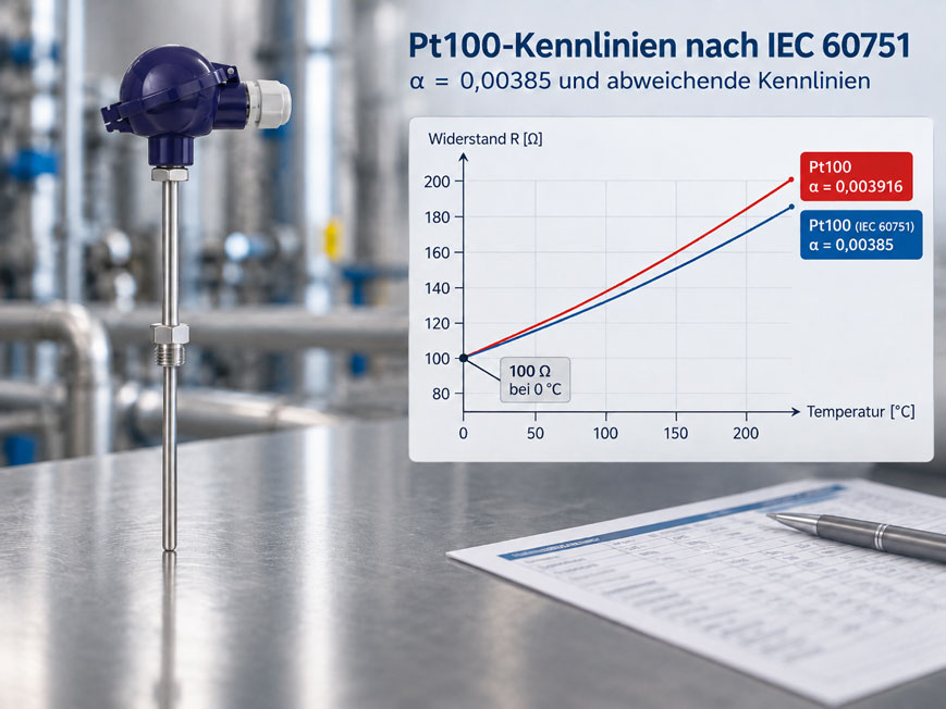
A Pt100 is tested at 0 °C and has a resistance of almost exactly 100.00 Ω. At first glance, everything therefore appears to be clear. Nevertheless, the connected temperature transmitter indicates several degrees too little or too much at higher temperatures. Sensor, wiring and connection are electrically correct. What could be causing the deviation?
One possible cause is the resistance-temperature characteristic curve selected in the transmitter. The designation Pt100 initially means only that the platinum measuring resistor has a nominal resistance of 100 Ω at 0 °C. How strongly this resistance changes as the temperature rises or falls is additionally determined by the sensor characteristic curve.
For industrial Pt100 sensors, the characteristic curve according to IEC 60751 with a temperature coefficient of approximately α = 0.00385 K⁻¹ is commonly used today. However, other or older platinum characteristic curves also exist. A transmitter may support both an IEC characteristic and alternative Pt characteristics, for example. If the wrong one is selected, the electronics interpret the same measured resistance as a different temperature.
The designation “Pt100” alone is therefore not always sufficient for parameterization, spare-part selection and troubleshooting. Nominal resistance and characteristic curve must match both in the sensor and in the evaluation electronics.
What does Pt100 actually mean?
A Pt100 is a platinum resistance sensor. The abbreviation Pt indicates platinum as the resistance material, while the number 100 describes the nominal resistance at 0 °C.
For an ideal Pt100 at the reference point:
R(0 °C) = 100 Ω
As the temperature rises, the electrical resistance of platinum increases. A Pt100 is therefore a resistance thermometer with a positive temperature coefficient.
However, the information 100 Ω at 0 °C describes only one single point on the characteristic curve. Two different platinum characteristic curves can have the same resistance at 0 °C and still differ significantly at 100 °C.
Which characteristic curve is defined by IEC 60751?
IEC 60751 defines the resistance-temperature relationship for industrial platinum resistance thermometers and platinum temperature sensors. The standard therefore describes not only tolerance classes, but also which resistance corresponds to a specific temperature value.
For the industrially common IEC Pt100, the characteristic is often referred to in simplified form as:
α ≈ 0.00385 K⁻¹
.
This value is a very practical way of identifying the sensor characteristic. However, the actual resistance-temperature relationship is calculated using a nonlinear mathematical function.
What does α = 0.00385 mean?
In simplified terms, the temperature coefficient α describes the relative change in resistance of the platinum sensor between 0 and 100 °C.
For the commonly used IEC characteristic, approximately:
α ≈ 0.00385 K⁻¹
is obtained.
This does not mean that the resistance of a Pt100 changes by exactly 0.385 Ω per kelvin over its entire temperature range. Rather, this value is an average coefficient between 0 and 100 °C.
Between these two points, the resistance increases from:
100 Ω at 0 °C
to approximately:
138.5 Ω at 100 °C
The average resistance change is therefore approximately:
(138.5 Ω - 100 Ω) / 100 K ≈ 0.385 Ω/K
What resistance values does an IEC Pt100 have?
Several typical resistance values are useful for a quick plausibility check.
| Temperature | Approximate Pt100 value according to IEC 60751 |
|---|---|
0 °C |
100.00 Ω |
25 °C |
approx. 109.7 Ω |
50 °C |
approx. 119.4 Ω |
100 °C |
approx. 138.5 Ω |
200 °C |
approx. 175.9 Ω |
These values are very useful for quick troubleshooting. If a removed Pt100 measures around 138.5 Ω at approximately 100 °C, this generally indicates the usual IEC characteristic.
For accurate testing, however, the standardized resistance values or the corresponding characteristic equation should be used.
Why is the Pt100 characteristic curve not exactly linear?
The change in resistance of a platinum sensor is not perfectly linear over a wide temperature range. Therefore, the simple relationship:
R = 100 Ω + temperature × 0.385 Ω/K
is not sufficient for precise temperature calculation.
For temperatures above 0 °C, the Pt100 characteristic is usually described by an equation of the form:
R(t) = R0 × (1 + A × t + B × t²)
.
For negative temperatures, an additional term is used. This mathematical description is often referred to in connection with the Callendar-Van Dusen equation.
Modern temperature transmitters perform this linearization automatically. However, this requires the sensor characteristic selected in the device to match the connected Pt100.
Which alternative Pt characteristic curves exist?
Not every Pt100 found in older systems or special applications necessarily follows exactly the IEC characteristic commonly used today.
Transmitters and calibrators may support several Pt characteristic curves, for example:
| Characteristic curve | Typical α value | Note |
|---|---|---|
| IEC 60751 | approx. 0.00385 |
Widely used industrial Pt characteristic today |
| Alternative/older Pt characteristic | approx. 0.003916 |
May occur in older or special systems |
| Other Pt characteristics | e.g. approx. 0.00391 |
Selectable depending on the device |
This can cause an error particularly when a transmitter is replaced: the existing sensor remains unchanged, but the new transmitter may use a different characteristic curve by default than the previous device.
What happens if the wrong characteristic curve is selected?
The temperature transmitter initially measures only an electrical resistance. It then has to convert this resistance into a temperature using the characteristic curve stored in its configuration.
If the sensor measures, for example:
138.5 Ω
a device correctly configured for IEC 60751 interprets this value as approximately:
100 °C
If a steeper Pt characteristic is configured instead, the transmitter assumes that the same resistance has already been reached at a lower temperature.
The error therefore typically increases with increasing distance from the common reference point.
Why is the error not apparent at 0 °C?
This is a particularly important error trap. Different Pt100 characteristic curves can have the same nominal resistance of 100 Ω at 0 °C.
A test carried out only at 0 °C therefore gives:
Sensor ≈ 100 Ω → indication ≈ 0 °C
and initially appears completely correct.
Only at a second temperature point does it become apparent whether the slope and characteristic shape match.
This is precisely why a one-point test at the ice point or zero point is not sufficient to uniquely identify the complete Pt100 characteristic.
Selecting the correct sensor characteristic in the temperature transmitter
With modern universal temperature transmitters, the sensor characteristic can often be parameterized. One specific example is the Siemens SITRANS TH320.
The transmitter supports resistance thermometers in 2-, 3- and 4-wire configurations and provides different RTD characteristics. In addition to the IEC 60751 platinum characteristic, alternative characteristics or freely definable special characteristics can also be used depending on the configuration.
During commissioning, at least the following parameters should therefore be checked:
- sensor type Pt100 or Pt1000,
- selected standard or characteristic curve,
- 2-, 3- or 4-wire connection,
- measuring range,
- unit °C or °F,
- customer-specific characteristic, if applicable.
A correct three-wire connection, for example, cannot compensate for an error caused by selecting the wrong sensor characteristic.
Distinguishing characteristic-curve errors from wiring errors
An incorrect Pt100 measurement can have many causes. The sensor characteristic is therefore only one possible source of error.
| Cause of error | Typical behaviour |
|---|---|
| Incorrect Pt characteristic | Systematic temperature-dependent deviation |
| Lead resistance with 2-wire connection | Additional resistance usually causes a positive temperature deviation |
| Incorrect 3-wire wiring | Lead compensation does not function correctly |
| Poor contact | Additional or unstable resistance |
| Sensor aging or damage | Sensor characteristic or stability changes |
| Incorrect sensor type | For example, connecting a Pt1000 to a Pt100 input causes a major misinterpretation |
During troubleshooting, the sensor resistance should therefore preferably be measured directly and compared with a known temperature reference point.
How can the characteristic curve be checked in practice?
At least two known temperature points are required to check the characteristic curve. A multipoint test across the actual temperature range used is even more informative.
A possible test procedure:
- Stabilize the sensor at a known temperature.
- Measure the resistance with a sufficiently accurate reference instrument.
- Compare the measured value with the IEC 60751 resistance table.
- Repeat the test at at least one significantly different temperature point.
- At the same time, check the parameterization of the connected transmitter.
This makes it possible to distinguish whether the sensor itself has an unexpected characteristic or whether only the evaluation electronics are configured incorrectly.
Practical example: Pt100 shows an incorrect value at 100 °C
A Pt100 resistance thermometer is connected to a new temperature transmitter. At room temperature, the indication initially appears plausible.
During a comparison test in a temperature calibrator, the reference temperature is exactly:
100.0 °C
Directly at the Pt100, approximately:
138.5 Ω
is measured.
The sensor therefore behaves plausibly like a Pt100 according to IEC 60751.
However, the temperature transmitter indicates a lower temperature. The parameterization reveals that Pt100 has been selected, but with an alternative characteristic having a higher temperature coefficient.
After changing the configuration to:
Pt100 – IEC 60751
the indicated temperature again agrees with the reference.
This example shows that even a fully functional Pt100 can produce a systematic measurement error if the sensor and evaluation electronics use different resistance-temperature characteristics.
Systematic procedure
- Clearly identify the sensor: Pt100, Pt1000 or another RTD?
- Check the standard or sensor characteristic in the datasheet or on the nameplate.
- Check the wiring: 2-, 3- or 4-wire.
- Measure the sensor resistance at a known temperature.
- Compare the resistance with the IEC 60751 table.
- Check at least one second temperature point.
- Select the correct sensor type in the transmitter.
- Check the configured characteristic curve.
- Check measuring range and unit.
- After changes, perform a comparison measurement.
- Document sensor and transmitter configuration.
Common mistakes
- Treating “Pt100” as a complete sensor definition: The nominal resistance alone does not fully describe the characteristic curve.
- Testing only at 0 °C: Different Pt100 characteristics have the same nominal resistance there and can therefore appear correct.
- Interpreting α = 0.00385 as an exactly linear slope: The actual IEC 60751 characteristic is not perfectly linear.
- Connecting an old sensor to a new transmitter without checking the characteristic: The new input may be configured for a different Pt type.
- Confusing Pt100 and Pt1000: Both generally use the same relative IEC characteristic, but have different nominal resistances.
- Interpreting a characteristic error as a wiring error: A 3- or 4-wire connection cannot correct an incorrectly parameterized sensor curve.
- Configuring the temperature transmitter only by measuring range: Sensor type, characteristic and connection type are equally important.
- Correcting a different characteristic with an offset: A characteristic-curve error changes with temperature and therefore cannot be meaningfully corrected over the complete range using a constant zero offset.
Pt100 sensors and temperature transmitters
One specific resistance thermometer for industrial applications is the WIKA TR10-B. The instrument is available with Pt100 or Pt1000 sensors and can be combined with different thermowells, connection heads and measuring inserts.
The spring-loaded measuring insert is replaceable. This means that the sensing element can be checked or replaced separately during maintenance or troubleshooting without necessarily replacing the complete measuring point.
For converting the resistance signal into a standardized process signal, the Siemens SITRANS TH320 is one suitable example. The universal temperature transmitter supports resistance thermometers in 2-, 3- and 4-wire configurations and allows different sensor characteristics to be configured.
This selection option illustrates why correct parameterization is so important: an electrically functional Pt100 will only provide the correct temperature value if the transmitter uses the same resistance-temperature characteristic.
Suitable sensors can be found under resistance thermometers / Pt100 sensors at ICS Schneider. Further information is available for the WIKA TR10-B resistance thermometer and the Siemens SITRANS TH320 temperature transmitter.
Conclusion
The designation Pt100 initially means that the platinum measuring resistor has a nominal value of 100 Ω at 0 °C. For correct temperature calculation, however, the resistance-temperature characteristic must also be known.
In industrial applications, the characteristic according to IEC 60751 with a temperature coefficient of approximately α = 0.00385 K⁻¹ is widely used today. Other or older Pt characteristics can have different resistance values at higher temperatures despite having the same 100 Ω zero point.
This is precisely why incorrect transmitter parameterization can initially remain unnoticed. At 0 °C, the sensor and evaluation may agree perfectly, while the temperature deviation becomes increasingly larger as the temperature moves farther away from the zero point.
In such a case, the cause of the error is neither necessarily the Pt100 itself nor the wiring. The electronics are simply interpreting a correct resistance measurement using the wrong characteristic curve.
For a reliable Pt100 measuring point, the following therefore applies: do not check only the nominal resistance, but also clearly identify the standard or characteristic curve, configure the sensor and transmitter for the same characteristic and verify the function at at least two different temperature points.
FAQ: Pt100 characteristic curve according to IEC 60751
What does Pt100 mean?
Pt stands for platinum and 100 refers to the nominal resistance of 100 Ω at 0 °C.
Which characteristic curve does a typical industrial Pt100 use?
In industrial applications, the characteristic according to IEC 60751 with a temperature coefficient of approximately α = 0.00385 K⁻¹ is widely used.
What resistance does a Pt100 have at 100 °C?
A Pt100 according to IEC 60751 has a resistance of approximately 138.5 Ω at 100 °C.
Does α = 0.00385 mean that the resistance always changes by exactly 0.385 Ω per degree?
No. 0.385 Ω/K is an average resistance change between 0 and 100 °C. The actual Pt100 characteristic is slightly nonlinear.
Are there different Pt100 characteristic curves?
Yes. In addition to the widely used IEC 60751 characteristic, other platinum characteristics with different temperature coefficients exist or existed. Universal transmitters can therefore often be configured for several different characteristics.
Can a Pt100 with the wrong characteristic still indicate correctly at 0 °C?
Yes. Different Pt100 characteristics can have the same nominal resistance of 100 Ω at 0 °C. The error only becomes visible at temperatures above or below the zero point.
What happens if the wrong Pt100 characteristic is selected in the transmitter?
The measured resistance is assigned to the wrong temperature. This produces a systematic temperature-dependent measurement deviation.
Can a characteristic-curve error be corrected with an offset?
Not meaningfully over the complete range. An offset is constant, while the error between two different characteristic curves varies with temperature.
How can you check whether a Pt100 follows the IEC 60751 characteristic?
The resistance should be measured at at least two known temperatures and compared with the corresponding IEC 60751 resistance values.
Is the characteristic curve different for Pt100 and Pt1000?
For IEC versions, Pt100 and Pt1000 generally use the same relative platinum characteristic. However, the Pt1000 has ten times the nominal resistance.
Which specific Pt100 sensor is suitable for industrial applications?
One example is the WIKA TR10-B resistance thermometer. It is available with Pt100 or Pt1000 measuring elements and can be configured for numerous industrial thermowell and process installations.
Which transmitter can process different RTD characteristic curves?
One example is the Siemens SITRANS TH320. It has a universal input for resistance thermometers and supports various standardized as well as customer-specific characteristic curves.