


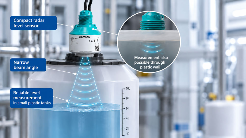
A small plastic tank in an industrial dosing system requires continuous level monitoring. The tank has an internal diameter of only 300 mm and is less than one meter high. A compact radar level sensor is mounted on the tank lid.
At low filling levels, the measurement works reliably. However, as soon as the tank is nearly full, the indication becomes unstable. At times, the sensor indicates an incorrect level or holds the last measured value.
The cause may be related to the tank geometry: In small plastic tanks, the liquid surface, tank wall and mounting opening are often very close to the radar antenna.
For reliable radar level measurement, antenna radiation characteristics, near range, mounting position and tank material are therefore at least as important as the maximum measuring range.
Modern compact radar level sensors often enable measurement with a very narrow radar beam. Suitable devices can even measure externally through a non-metallic plastic tank wall or a corresponding lid.
This article explains what needs to be considered when planning measurements in small plastic tanks and how to correctly evaluate measuring distance, antenna beam angle and unwanted reflections.
Table of Contents
- Measurement Task and Typical Problems
- How Radar Level Measurement Works
- Antenna Size and Beam Angle
- Considering Small Tank Geometries
- Dead Zone and Minimum Measuring Distance
- Radar Measurement Through Plastic Tank Walls
- Selecting a Suitable Mounting Position
- Practical Example: Calculating Radar Beam Width and Measuring Distance
- Influence of Medium Properties
- Wall Reflections and Multiple Echoes
- Mounting Nozzles and Lid Openings
- Correctly Relating Filling Height and Measuring Distance
- Using False Echo Suppression Correctly
- Condensation and Deposits
- Inlet Pipes and Internal Tank Components
- Considering Temperature and Pressure
- Measurement Signals and PLC Integration
- Limit Values and Overfill Protection
- Alternative Level Measurement Methods
- Testing and Commissioning Procedure
- Typical Faults and Diagnostics
- Suitable ICS Products
- Conclusion
- Frequently Asked Questions
1. Measurement Task and Typical Problems
Small plastic tanks are used to store water, cleaning agents, process chemicals or industrial liquids, for example.
Level measurement is often required without direct contact with the medium while also occupying minimal installation space.
Typical difficulties arise from short measuring distances, unfavorable mounting openings, wall reflections and weak product echoes.
Particularly at high filling levels, it must be verified whether the liquid surface is still within the permissible measuring range.
2. How Radar Level Measurement Works
A free-space radar level sensor transmits electromagnetic waves toward the surface of the medium.
Some of these waves are reflected and received by the sensor.
With FMCW radar, the distance to the surface is determined from the characteristics of the transmitted and received frequency-modulated signals.
When measuring from above, the measured distance normally decreases as the filling level rises.
To convert the measured distance into a filling height, the instrument requires a correctly defined reference point and the tank geometry.
3. Antenna Size and Beam Angle
The antenna influences how strongly the radar beam is focused. For small tanks, a compact sensor with a narrow beam angle can be advantageous.
With a narrow measuring beam, a smaller area of the tank is directly irradiated. This makes it easier to avoid certain internal components and wall areas.
However, antenna size alone does not describe the overall measurement performance. Antenna design, operating frequency, signal processing and actual installation conditions are decisive.
Compact 80 GHz radar sensors are used in the Siemens SITRANS LR100 series. The beam angle varies between individual versions.
4. Considering Small Tank Geometries
In a large storage tank, the radar beam can often reach the surface almost unobstructed over several meters.
In a small tank, however, side walls, inlet connections and the liquid surface are close together.
Additionally, curved lids, inclined walls or conical tank bottoms can generate multiple reflections.
Before selecting an instrument, at least the tank height, internal diameter, lid shape, maximum filling level and existing internal components should therefore be known.
5. Dead Zone and Minimum Measuring Distance
The dead zone, also known as the blocking distance, describes an area in which the instrument cannot guarantee reliable level measurement under the specified conditions.
These areas can be very small with compact radar sensors. However, the actual minimum distances vary depending on the instrument.
For example, the manufacturer’s instructions for the WIKA ILT-C01 and ILT-C05 specify a minimum measuring distance of 100 mm from the sensor tip.
The Siemens SITRANS LR100 series is also designed for short measuring distances. Nevertheless, its specific near-range performance must be verified based on the respective instrument configuration and installation conditions.
A maximum measuring range of several meters does not indicate whether a sensor can reliably detect the last few centimeters below the tank lid.
6. Radar Measurement Through Plastic Tank Walls
Electromagnetic radar waves can pass through suitable non-metallic plastics.
Under appropriate conditions, a sensor designed for this purpose can therefore be mounted outside a closed plastic tank.
Measurement from above through a suitable plastic lid is particularly interesting. This can eliminate the need for an additional process opening.
However, plastic tanks are not inherently transparent to radar. Wall thickness, fillers, metallic coatings and reinforcements can influence the signal.
Moisture or liquid films on the lid can also cause unwanted reflections.
The suitability of measurement through the tank wall must therefore be verified for the specific material and actual installation.
7. Selecting a Suitable Mounting Position
The sensor should be aligned as unobstructed as possible toward a representative surface of the medium.
In small tanks, the greatest possible distance from interfering internal components and wall areas is advantageous.
For certain SITRANS LR100 versions, Siemens recommends a minimum distance of 200 mm from the tank wall. If this cannot be achieved due to the geometry, suitable false echo suppression is particularly important.
| Criterion | Possible Influence | Planning Recommendation |
|---|---|---|
| Tank diameter | Short distance to the side wall | Check antenna beam angle and false echoes |
| Maximum filling level | Insufficient distance to the antenna | Consider the instrument-specific blocking distance |
| Plastic lid | Reflection or attenuation of the radar signal | Check material and wall thickness |
| Metallic reinforcements | Strong additional reflections | Keep the radar beam unobstructed |
| Inlet pipe | False echoes and moving liquid surface | Avoid measuring directly into the incoming liquid stream |
| Mounting nozzle | Reflections in the near range | Select nozzle geometry according to manufacturer specifications |
8. Practical Example: Calculating Radar Beam Width and Measuring Distance
A hypothetical cylindrical plastic tank has an internal diameter of 300 mm and a usable height of 800 mm.
A radar level sensor is mounted vertically above the tank. The distance between the assumed sensor reference point and the tank bottom is 850 mm.
The maximum operational filling level is 700 mm.
8.1 Initial Data
- Tank internal diameter: 300 mm.
- Tank height: 800 mm.
- Distance from sensor reference point to tank bottom: 850 mm.
- Maximum operational filling level: 700 mm.
- Example radar beam angles: 4°, 8° and 12°.
- Distance considered for beam diameter: 600 mm.
All geometric values are hypothetical calculation assumptions. The calculation describes an idealized radar beam and does not constitute a complete assessment of measurement suitability.
8.2 Distance at Maximum Filling Level
The distance between the sensor reference point and the liquid surface is:
d = H – h
d = 850 mm – 700 mm
d = 150 mm
At the maximum operational filling level, a measuring distance of 150 mm therefore remains.
This distance is greater than the specified minimum measuring distance of 100 mm for the WIKA ILT-C01. However, this does not yet demonstrate complete suitability of the instrument.
8.3 Calculating the Radar Beam Diameter
For an idealized conical radar beam geometry:
DBeam = 2 · d · tan(α/2)
Here, α is the total beam angle.
With a beam angle of 8° and a distance of 600 mm:
DBeam = 2 · 600 mm · tan(4°)
DBeam ≈ 84 mm
8.4 Comparison with 4° and 12°
For 4°:
DBeam = 2 · 600 mm · tan(2°)
DBeam ≈ 42 mm
For 12°:
DBeam = 2 · 600 mm · tan(6°)
DBeam ≈ 126 mm
8.5 Distance to the Tank Wall
With central mounting, the distance between the radar axis and the inner tank wall is:
300 mm / 2 = 150 mm
The tank is therefore too small to meet the 200 mm wall clearance recommended by Siemens for certain LR100 versions.
This does not automatically mean that radar measurement is impossible. However, the installation must be examined particularly carefully and suitable false echo suppression must be performed.
8.6 Summary of Results
| Parameter | Calculation | Result |
|---|---|---|
| Tank internal diameter | Assumed | 300 mm |
| Tank height | Assumed | 800 mm |
| Sensor distance to tank bottom | Assumed | 850 mm |
| Maximum filling level | Assumed | 700 mm |
| Distance at maximum filling level | 850 – 700 | 150 mm |
| Wall clearance with central mounting | 300 / 2 | 150 mm |
| Beam diameter at 4° and 600 mm | 2 · 600 · tan(2°) | Approx. 42 mm |
| Beam diameter at 8° and 600 mm | 2 · 600 · tan(4°) | Approx. 84 mm |
| Beam diameter at 12° and 600 mm | 2 · 600 · tan(6°) | Approx. 126 mm |
| WIKA ILT-C01 minimum measuring distance | Manufacturer specification | 100 mm |
8.7 Interpreting the Result
A narrow radar beam can be advantageous in a small tank. However, the geometric calculation only shows the approximate beam spread.
The actual echo behavior is additionally influenced by near-field effects, the tank lid, the medium, internal components and multiple reflections.
A calculated radar beam that is sufficiently narrow is therefore not proof of interference-free level measurement.
9. Influence of Medium Properties
The strength of the product echo depends, among other factors, on the dielectric constant of the medium.
Liquids with a very low dielectric constant can produce weaker reflections than water, for example.
For the WIKA ILT-C01 and ILT-C05, the manufacturer’s operating instructions specify a minimum dielectric constant of 2 for the medium.
Foam, strong surface movement and deposits can also influence the measurement.
Suitability must therefore be evaluated based on both the tank geometry and the specific liquid.
10. Wall Reflections and Multiple Echoes
A radar sensor does not receive only the echo from the liquid surface.
Tank walls, lids, internal components and other solid structures can also reflect radar waves.
In small tanks, these reflection points are often located close to the intended measuring range.
Multiple reflections can occur particularly with curved lids. The sensor may then temporarily evaluate a false echo instead of the actual product echo.
11. Mounting Nozzles and Lid Openings
An unfavorable mounting nozzle can cause additional reflections.
Particularly long and narrow metallic nozzles can influence the radar beam.
For small plastic tanks, mounting externally on the lid may be useful if this arrangement is approved for the application.
Whether direct threaded installation or non-contact external mounting is more suitable depends on the tank and the specific instrument configuration.
12. Correctly Relating Filling Height and Measuring Distance
Radar sensors initially measure the distance to the surface of the medium.
The filling height is calculated from the configured reference distance and the measured distance.
If the zero point is defined incorrectly, the level indication may be offset across the entire measuring range.
In small tanks, even a reference height error of a few centimeters can cause a considerable relative level measurement error.
13. Using False Echo Suppression Correctly
Modern radar sensors can detect fixed reflections and take them into account during signal evaluation.
Automatic false echo suppression is available on suitable Siemens SITRANS LR100 versions.
This function can be particularly important when the distance to the tank wall is small.
False echo suppression should be performed under suitable, documented filling conditions.
The actual product echo must not accidentally be suppressed as a permanent false echo.
14. Condensation and Deposits
Condensate can form on the sensor antenna or on the inside of a plastic lid.
Even when measuring externally, moisture on the tank lid can generate additional reflections.
Droplets, liquid films and changing wetting conditions are particularly critical.
For applications where these conditions may occur, signal reserve and measurement behavior must also be checked under the expected moisture conditions.
15. Inlet Pipes and Internal Tank Components
The sensor should not be mounted directly above an incoming liquid stream.
Incoming liquid can cause significant surface movement and additional reflections.
Agitators, suction pipes, braces and other internal components must also be considered.
A suitable mounting position should be directed toward a representative liquid surface that is as unobstructed as possible for the radar beam.
16. Considering Temperature and Pressure
Permissible process and ambient temperatures must be considered when selecting a sensor.
In its standard configuration, the WIKA ILT-C01 is intended for suitable applications up to 100 °C. The ILT-C05 is available as a high-temperature version for applications up to 150 °C.
For Siemens devices, permissible temperatures and pressures differ depending on the SITRANS LR100 version.
The chemical resistance of the process connection must also be considered when the instrument is installed in contact with the medium.
17. Measurement Signals and PLC Integration
Radar level sensors can provide analog or digital signals, depending on their configuration.
Different communication variants are available within the Siemens SITRANS LR100 series, including 4–20 mA, HART or Modbus RTU on suitable versions.
Depending on the configuration, the WIKA ILT-C01 provides corresponding analog outputs and optional switching outputs.
The measuring span, level reference, unit and fault conditions must be clearly defined for the PLC.
18. Limit Values and Overfill Protection
Small tanks frequently require limit alarms for maximum or minimum filling levels.
On suitable instrument versions, these alarms can be implemented using switching outputs or the higher-level controller.
It is important to distinguish between an operational alarm and a required safety-related protective function.
According to their operating instructions, the WIKA ILT-C01/ILT-C05 must not be used as safety or emergency shutdown devices.
If independent overfill protection or a safety-related shutdown is required, a suitably designed and assessed protective function must be provided.
19. Alternative Level Measurement Methods
Radar is not automatically the best solution for every small plastic tank.
For suitable liquids, hydrostatic pressure sensors may be used, for example.
Capacitive, optical or float-based measurement methods may also be suitable for certain media and tanks.
Selection depends on measuring range, medium, installation space, tank material and whether continuous or point level measurement is required.
20. Testing and Commissioning Procedure
The following procedure is recommended for traceable radar level measurement in small plastic tanks:
- Record tank height, internal diameter and lid geometry.
- Check the medium, dielectric constant and process conditions.
- Define the required minimum and maximum filling levels.
- Compare radar frequency, beam angle and minimum measuring distance.
- Select a suitable mounting position.
- For external mounting, check the plastic wall and its thickness.
- Configure the sensor reference point and level scaling.
- Perform false echo suppression under suitable conditions.
- Check measurement behavior at low and high filling levels.
- Document signals, alarms and configuration.
For particularly small tanks, testing under actual installation conditions is advisable.
21. Typical Faults and Diagnostics
Measured value jumps at high filling levels: Possible causes include insufficient measuring distance, near-range reflections or incorrect false echo suppression.
Sensor indicates a consistently incorrect value: Check the reference point, level scaling and possible fixed reflections.
Measurement through the plastic lid does not work: Check the material, wall thickness, coatings, metallic inserts and moisture.
Measured value fluctuates during filling: Check the incoming liquid stream, moving surface and configured signal damping.
No stable product echo: Investigate the dielectric constant, unobstructed measuring path, antenna alignment and signal processing.
22. Suitable ICS Products
ICS Schneider Messtechnik offers various compact radar level sensors for industrial tank applications.
| Product | Important Features | Typical Application |
|---|---|---|
| Siemens SITRANS LR100 | 80 GHz radar, compact design, measuring distance up to 8 m | Simple continuous level measurement |
| Siemens SITRANS LR110 | 80 GHz radar, communication and approval options, up to 15 m | Industrial tank monitoring |
| Siemens SITRANS LR120 | 80 GHz radar, narrow beam angle, up to 30 m | More demanding measurement applications |
| WIKA ILT-C01 | 60 GHz radar, minimum measuring distance 100 mm, up to 5 m | Small plastic tanks and mobile applications |
| WIKA ILT-C05 | 60 GHz radar, high-temperature version up to 150 °C | Suitable applications at elevated temperatures |
| Siemens SITRANS LT500 | Evaluation instrument for compatible level measurement systems | Higher-level indication, alarming and control system integration |
22.1 Siemens SITRANS LR100 Series
The Siemens SITRANS LR100 series includes compact radar level transmitters using 80 GHz technology.
The narrow measuring beam enables use in numerous compact tanks. Siemens also explicitly describes non-contact measurement through suitable plastic tank walls.
The series includes LR100, LR110, LR120, LR140 and LR150, among others. Differences include measuring distance, communication and instrument configuration.
Siemens SITRANS LR100 Series – Product Information
22.2 WIKA ILT-C01
The WIKA ILT-C01 is a compact industrial radar level sensor for suitable water-based and oil-based media as well as certain bulk solids.
It operates using 60 GHz FMCW radar. The specified measuring distance is 100 to 5,000 mm, with a beam angle of ±6°.
Of particular interest is the possibility of mounting the sensor externally on suitable plastic tanks.
WIKA ILT-C01 – Product Information
22.3 WIKA ILT-C05
The WIKA ILT-C05 is the high-temperature version of the industrial radar level sensor family.
It also uses the 60 GHz measuring principle and is intended for suitable applications up to 150 °C.
Suitability for the respective medium, temperature and installation conditions must be checked against the instrument documentation.
WIKA ILT-C05 – Product Information
22.4 Siemens SITRANS LT500
The Siemens SITRANS LT500 is an evaluation instrument for compatible radar level sensors and other suitable measuring systems.
It provides corresponding indication, evaluation and alarm functions as well as integration into industrial automation systems.
Siemens SITRANS LT500 – Product Information
22.5 Selecting a Suitable Radar Sensor
For a specific selection, the tank height, diameter, plastic material, wall thickness, medium, temperature, required level range and output signals should be known.
Particularly for very small tanks, testing the complete measuring point under realistic operating conditions is recommended.
Additional Level Measurement Technology at ICS Schneider Messtechnik
23. Conclusion
Radar level measurement is also possible in small plastic tanks. However, correct instrument selection and mounting that matches the tank geometry are essential.
A narrow radar beam can reduce reflections from walls and internal components. At the same time, the permissible minimum measuring distance and maximum filling level must be considered.
For suitable plastic tanks, mounting outside the tank can offer advantages because no additional opening into the process medium is required.
However, the material properties of the tank wall and possible unwanted reflections must be checked.
The key conclusion is: The maximum measuring distance alone does not determine whether a radar sensor is suitable. Particularly in small plastic tanks, antenna radiation characteristics, dead zone, mounting position and false echo behavior are decisive.
24. Frequently Asked Questions
24.1 Is Radar Suitable for Level Measurement in Small Plastic Tanks?
Yes. Suitable compact radar sensors can also be used in small tanks. However, minimum measuring distance, antenna beam angle and tank geometry must be considered.
24.2 Can Radar Measure Through a Plastic Wall?
Yes, through suitable non-metallic plastic materials. Measurement from above through an appropriate plastic lid is particularly feasible.
24.3 Which Plastic Tanks Are Suitable?
This depends on the material, wall thickness, coating and any fillers. A general approval for all plastics is not possible.
24.4 Why Is the Antenna Beam Angle Important?
It influences the spatial spread of the radar beam. A narrow beam can help avoid interfering internal components and wall areas.
24.5 What Is the Dead Zone of a Radar Sensor?
It describes a near-range area in which the specified level measurement is not guaranteed. Its size depends on the instrument configuration.
24.6 What Minimum Measuring Distance Does the WIKA ILT-C01 Require?
The WIKA operating instructions specify a minimum measuring distance of 100 mm from the sensor tip.
24.7 Can a Radar Sensor Measure Right Up to the Tank Lid?
This depends on the sensor and its near-range specifications. The achievable measuring distance must not be assumed to be identical for all radar instruments.
24.8 Is 80 GHz Radar Better Suited for Small Tanks?
80 GHz instruments often enable compact antennas with narrow beam angles. However, the overall instrument design and specific application remain decisive.
24.9 Why Do Reflections Occur at the Tank Wall?
Radar waves can also be reflected by tank walls and other solid structures. In small tanks, such echoes can influence signal evaluation.
24.10 Where Should the Sensor Be Mounted?
Ideally, it should detect a representative liquid surface while avoiding interfering internal components and reflection points.
24.11 Can the Sensor Be Positioned Directly Above an Inlet Pipe?
This should be avoided wherever possible because incoming liquid can cause additional false echoes and surface movement.
24.12 What Is False Echo Suppression?
It enables suitable radar sensors to account for or suppress certain fixed reflections during measured value evaluation.
24.13 Does Condensation Affect Radar Measurement?
Yes. Droplets or liquid films can cause additional reflections. The actual effect depends on the sensor and installation conditions.
24.14 Can Radar Also Measure Oil Levels?
Yes, provided the respective sensor is suitable for the medium. The dielectric constant and specific instrument configuration must be considered in particular.
24.15 Which Radar Sensors Does ICS Offer for Plastic Tanks?
Examples from the ICS product range include the Siemens SITRANS LR100 series and the WIKA ILT-C01 and ILT-C05.
24.16 Can Radar Level Measurement Provide Overfill Protection?
Suitable functions are available for operational limit alarms. However, a safety-related overfill protection function requires an appropriately designed and approved protective system.
24.17 What Alternatives Are Available for Very Small Tanks?
Depending on the medium and installation conditions, hydrostatic, capacitive, optical or float-based level measurement methods may be more suitable.
24.18 What Information Does ICS Need to Prepare a Quotation?
The required information includes tank material, internal diameter, height, wall thickness, medium, temperature, level range, mounting position, desired signal and required approvals.