


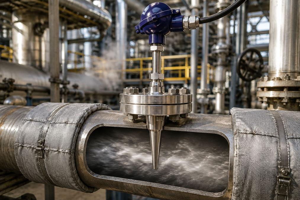
A thermowell separates the temperature sensor from the process medium. It protects the sensing element against pressure, flow, corrosion, abrasion and mechanical loads. At the same time, many designs allow the measuring insert to be replaced without opening the pipe or vessel.
However, this protective function makes the thermowell a component subjected to high mechanical and thermal loads. It projects into the flow as a cantilever, is exposed to transverse forces from the medium and can be excited into vibration by vortex shedding. If the thermowell’s natural frequency is unfavourably aligned with the excitation frequency, resonance, material fatigue and ultimately vibration-induced failure may occur.
The thermowell also influences the temperature measurement itself. An insufficient insertion depth can cause heat-conduction errors. A very heavy-duty thermowell may improve mechanical safety, but it also increases thermal mass and extends the response time. A design that is as long and thin as possible is therefore no more universally correct than one that is particularly short and massive.
For reliable sizing, measuring accuracy, response time, process pressure, temperature, flow velocity, material resistance, connection geometry and vibration behaviour must be assessed together.
Suitable designs can be found in the thermowells category. Compatible resistance thermometers, thermocouples and other sensor designs are available in the temperature sensors and temperature probes section.
Contents
- What function does a thermowell perform?
- Which process data are required for sizing?
- Distinguishing between installation length, insertion depth and unsupported length
- Insertion depth for reliable temperature measurement
- Heat-conduction errors caused by an excessively short thermowell
- Thermowells in small pipe sizes
- Which forces are generated by the flow?
- Understanding vortex shedding and resonance
- When is a wake-frequency calculation required?
- Straight, tapered and stepped thermowells
- Solid-machined or fabricated design?
- Considering material, corrosion and abrasion
- Selecting the correct process connection and mounting
- Bore, measuring insert and response time
- Defining the installation point and flow direction
- Can the temperature sensor be replaced during operation?
- Typical design and sizing errors
- Practical example: Thermowell in a steam line
- Recommended sizing and commissioning procedure
- Which products are suitable?
- Conclusion
- Frequently asked questions
What function does a thermowell perform?
A thermowell, sometimes also referred to as a protection tube or pocket, forms a pressure-retaining barrier between the process medium and the temperature sensor. The actual measuring insert is located inside an internal bore and does not come into direct contact with the medium.
The thermowell can protect the sensor against:
- process pressure and pressure fluctuations,
- high flow velocities,
- corrosive or abrasive media,
- mechanical impacts and particles,
- vibrations from the pipework and plant,
- direct chemical exposure of the sensing element.
Separation from the process also simplifies maintenance. With a suitable design, the measuring insert can be removed from the thermowell and replaced or calibrated while the thermowell remains installed as a closed process barrier.
However, these advantages come at a cost. The thermowell adds an additional heat-transfer path between the medium and the sensor. It increases the thermal mass of the measuring point and itself becomes a component exposed to flow-induced mechanical loads. Sizing is therefore not simply a matter of selecting a length and thread size.
Which process data are required for sizing?
A thermowell can only be assessed for a defined process condition. The statement “steam line, 20 bar”, for example, is not sufficient. The actual and maximum possible operating conditions are required for thermal and mechanical sizing.
The most important information includes:
- medium and exact composition,
- minimum, normal and maximum process pressure,
- minimum, normal and maximum temperature,
- flow velocity at the installation point,
- density and viscosity of the medium,
- internal pipe diameter and wall thickness,
- volumetric or mass flow rate,
- mounting position and flow direction,
- type and dimensions of the process connection,
- required insertion depth,
- material and corrosion requirements,
- required response time,
- possible start-up, shutdown and fault conditions.
For gases and steam in particular, the actual flow velocity under operating conditions must be used. A standard volumetric flow rate cannot be used directly for mechanical sizing without considering pressure and temperature.
Possible special operating conditions must also be considered in addition to normal operation. Bypass operation, depressurisation, a start-up process or a modified control valve may locally generate a higher velocity than steady-state rated operation.
Distinguishing between installation length, insertion depth and unsupported length
Several length definitions are used for thermowells and must not be confused. Depending on the manufacturer and connection design, the geometric reference points may also differ. The dimensions used must therefore be clearly defined in the drawing.
The following are particularly important:
- Overall length: complete thermowell length including the connection area,
- Insertion or immersion length: length projecting into the medium from the inner pipe wall or process-side reference surface,
- Unsupported length: mechanically effective length between the mounting point and thermowell tip,
- Measuring-insert length: length of the temperature sensor inside the thermowell.
For temperature measurement, the position of the sensing element relative to the flow is decisive. For the vibration calculation, however, the mechanically unsupported length is relevant. An apparently identical catalogue length can therefore result in different mechanical behaviour when used with two different weld sockets or flange necks.
Insertion depth for reliable temperature measurement
The thermowell tip should reach an area whose temperature is representative of the process. In a pipe, this area is often located further away from the pipe wall because a thermal boundary layer may form there.
There is no universally applicable minimum immersion depth. The suitable length depends on factors such as pipe diameter, medium, flow velocity, temperature difference relative to the surroundings, sensor type and thermowell geometry.
The following should be checked when defining the length:
- Is the measuring tip located within the main flow?
- Is the temperature-sensitive sensing element fully immersed?
- How far is it from the pipe wall?
- Is there a large temperature difference between the process and the surroundings?
- Can heat be conducted away through the thermowell, neck tube or connection head?
- Does the intended length remain mechanically safe?
A thermowell extending to the centre of the pipe may be beneficial for measurement purposes, but it is not automatically mechanically permissible. The further the thermowell projects into the flow, the greater the lever arm, bending moment and susceptibility to vibration. The required insertion depth must therefore be coordinated with the mechanical calculation.
Heat-conduction errors caused by an excessively short thermowell
A temperature sensor measures the temperature of its sensing element. For this temperature to correspond as closely as possible to the process temperature, the heat flow from the medium to the sensor must be significantly greater than the unwanted heat flow through the thermowell and process connection to the surroundings.
If the insertion depth is too short, part of the process heat may be conducted through the metallic stem to the pipe wall, process connection or surroundings. With a hot medium, the sensor will then often indicate a value that is too low. With a cold medium, the indicated value may accordingly be too high.
The error becomes more likely with:
- large temperature differences between the medium and surroundings,
- low flow or stagnant medium,
- thick thermowells with high thermal conductivity,
- short insertion depth,
- missing pipe insulation,
- massive process connections,
- a measuring tip close to the pipe wall.
A greater insertion depth can reduce the error, but must not be implemented without a mechanical assessment. Alternatively, a different measuring point, angled installation, a larger pipe section or improved insulation may be appropriate.
Thermowells in small pipe sizes
Small pipes create a conflict of objectives. A thermowell inserted deeply enough may block a large proportion of the available cross-section and increase the pressure loss. At the same time, a very short design may cause heat-conduction errors.
Possible solutions include:
- installation in a pipe elbow,
- angled installation with a greater effective immersion depth,
- use of a suitable T-piece or measuring chamber,
- local enlargement of the pipe size,
- a smaller, fast-response thermowell tip,
- an alternative sensor design where process conditions allow safe direct measurement.
However, angled installation or installation in an elbow changes the incident flow and mechanical load. It must not be selected solely on the basis of the available installation length, but must be included in the mechanical assessment.
Which forces are generated by the flow?
The thermowell projects into the pipe in a similar manner to a cantilever beam. The medium flowing past exerts a transverse force on the exposed surface. This force produces a bending moment at the thermowell root.
The load increases with factors including:
- higher flow velocity,
- greater medium density,
- larger outside diameter,
- longer unsupported insertion length,
- unfavourable connection and mounting geometry,
- pulsating or highly turbulent flow.
Because the flow force acts on the thermowell root through a lever arm, even a comparatively small increase in unsupported length can significantly increase the mechanical load.
A sufficient wall thickness is important, but does not solve every problem. A thicker thermowell has greater mass and a different natural frequency. At the same time, the exposed area increases and the response time may become longer.
Understanding vortex shedding and resonance
When a medium flows past a thermowell, vortices are shed alternately from either side. A so-called Kármán vortex street can develop downstream of the thermowell. The alternating vortex shedding generates periodic transverse forces and can excite the thermowell into vibration.
The vortex shedding frequency can be described in simplified form by:
fs ≈ St × v / d
Where:
- fs = vortex shedding frequency,
- St = Strouhal number,
- v = local flow velocity,
- d = characteristic outside diameter.
The natural frequency of the thermowell, by contrast, is determined by its length, diameter, wall thickness, shape, material, mounting and mass. If the excitation frequency lies within a critical range of the natural frequency, the vibration amplitude can increase.
Under resonance conditions, the alternating stress rises considerably. The static process pressure may remain completely within the permissible limits while the thermowell still fails due to fatigue.
Vibration-induced failure frequently occurs near the mounting point, where the bending stress is highest. Such a failure can cause process leakage, loss of the temperature sensor and, with hazardous media, significant safety risks.
When is a wake-frequency calculation required?
Where relevant flow loads are present, a thermowell should not be selected solely on the basis of experience or an existing drawing. A wake-frequency calculation in accordance with ASME PTC 19.3 TW-2016 is frequently performed for one-piece, solid-machined thermowells.
The calculation assesses factors including:
- static loads caused by process pressure and flow,
- dynamic loads caused by vortex shedding,
- the natural frequency of the thermowell,
- excitation in the direction of and transverse to the flow,
- stress at the thermowell root,
- permissible material stress at the process temperature.
Both process data and complete geometric data are required for the calculation. These include the unsupported length, root and tip diameters, bore diameter, tip thickness, radii, material, pressure, temperature, velocity, density and viscosity.
The standardised calculation does not automatically apply to every protection tube. Its scope particularly covers solid-machined, straight, tapered or stepped thermowells. Fabricated, very thin-walled, hygienic or otherwise non-standard designs may require a different or manufacturer-specific assessment.
A completed calculation is also valid only for the process data on which it was based. If the flow rate, medium, pressure, temperature, pipe diameter or insertion length is subsequently changed, it must be checked whether the calculation remains applicable.
Straight, tapered and stepped thermowells
| Design | Typical characteristics | Important assessment |
|---|---|---|
| Straight | Simple design with a largely constant outside diameter | Robust for many moderate applications, but with a comparatively large exposed area and high mass |
| Tapered | Outside diameter decreases towards the tip | Favourable ratio of stiffness, mass and flow load; often suitable for higher velocities |
| Stepped | Reduced tip diameter with a stronger root section | Lower thermal mass at the tip and potentially faster response; transition geometry must be assessed mechanically |
A tapered design is not automatically resistant to vibration under all conditions. Likewise, a stepped tip is not automatically the fastest solution. The complete dimensions, material and specific process data are decisive.
If an existing thermowell does not pass the vibration calculation, the following modifications may be considered depending on the application:
- reducing the unsupported insertion length,
- increasing the root diameter,
- changing the tip or stem geometry,
- selecting a material with suitable strength,
- changing the process connection or mounting arrangement,
- relocating the measuring point to a more favourable flow position,
- using a special vortex-reducing thermowell design.
These measures influence one another. Reducing the insertion length, for example, may improve mechanical safety while increasing the heat-conduction error.
Solid-machined or fabricated design?
One-piece thermowells are bored and externally machined from a solid bar. They have no longitudinal or tip weld exposed to the process and provide high mechanical reserves. Solid-machined designs are frequently used at high pressures, high flow velocities and in demanding process plants.
Fabricated thermowells generally consist of a tube, end cap and process connection that are welded together. They are economical and can be suitable for moderate mechanical loads.
| Design | Advantages | Typical limitations |
|---|---|---|
| Solid-machined | High strength, defined geometry and suitable for mechanical calculations | Higher weight, greater machining effort and generally higher costs |
| Fabricated and welded | Economical, flexible dimensions and sometimes lower thermal mass | Welds, wall thickness and operating limits must match the process load |
The decision must not be based solely on process pressure. Flow, vibration, corrosion, temperature cycling, inspection requirements and the consequences of a possible failure must also be considered.
Considering material, corrosion and abrasion
The thermowell material must be suitable for the process both chemically and mechanically. A material with high strength is unsuitable if it is corroded by the medium. Conversely, a highly corrosion-resistant material may have different strength properties at high temperature or under dynamic loading.
Typical material groups include:
- stainless steels such as 1.4404 or 316L for many general applications,
- duplex steels for higher strength and certain chloride-containing media,
- nickel-based alloys for aggressive chemicals or high temperatures,
- titanium for selected corrosive media and seawater applications,
- special materials or coatings for highly corrosive or abrasive processes.
Suitability must always be checked against the specific concentration, temperature, flow and possible contaminants. General material-resistance tables do not replace an application-specific assessment.
Corrosion and abrasion reduce the wall thickness during operation. This changes the strength, natural frequency and vibration behaviour of the thermowell. A calculation that was originally sufficient may cease to be valid as material loss progresses.
Suitable inspection intervals and methods should therefore be defined for critical applications. Depending on the design and risk, visual inspection, dimensional checks, dye-penetrant testing, ultrasonic testing or other non-destructive tests may be appropriate.
Selecting the correct process connection and mounting
The process connection seals the measuring point and at the same time forms the mechanical mounting of the thermowell. Its design therefore influences the unsupported length and the resulting stresses.
Typical connection types include:
- threaded connections for compact and readily accessible measuring points,
- flanged connections for high loads, defined pressure ratings and removable process connections,
- welded connections for permanently tight and mechanically stable installations,
- clamp and hygienic connections for food, pharmaceutical and bioprocess applications.
For threaded connections, the thread type, engagement length, sealing principle and permissible tightening torque must be compatible. The subsequent use of long adapters can change the effective mounting point and create additional lever arms.
For flanges, nominal size, pressure rating, facing, material, gasket and bolts must match the process. The flange pressure rating alone does not confirm the strength of the thermowell itself.
Welded joints must be produced using a suitable process by qualified personnel. An unplanned field weld can alter the material structure, corrosion resistance and mechanical properties.
Bore, measuring insert and response time
Several heat-transfer stages exist between the thermowell and the sensing element. The medium first heats the outside surface of the thermowell. The heat must then pass through the wall, across the internal gap and through the measuring insert to the sensing element.
The response time is influenced by:
- outside diameter and wall thickness of the thermowell,
- material and thermal conductivity,
- shape and diameter of the thermowell tip,
- bore diameter,
- outside diameter of the measuring insert,
- air gap between the measuring insert and bore,
- contact between the sensor tip and thermowell bottom,
- spring force of a spring-loaded measuring insert,
- flow velocity and heat transfer from the medium.
The measuring insert should reliably reach its intended position. If it is too short, the sensing element will not contact the thermowell tip. An air gap can then result in a considerably slower and potentially inaccurate measurement.
A spring-loaded measuring insert can improve contact with the thermowell tip and compensate for length tolerances. Excessive spring force, an incorrect insert length or mechanical jamming must also be avoided.
Thermally conductive materials can improve thermal coupling, but they must be suitable for the temperature, medium, installation and subsequent replaceability. An arbitrary paste must not be introduced into a thermowell without approval.
Defining the installation point and flow direction
Even a correctly calculated thermowell can provide unreliable values at an unsuitable measuring point. Directly downstream of pipe bends, valves, orifice plates, reducers or mixing points, uneven velocity and temperature profiles may occur.
The following should be checked when selecting the installation point:
- Is the medium sufficiently mixed at this location?
- Is the temperature profile representative?
- Are strong turbulence or pulsating flow present?
- Can a gas or liquid layer form?
- Are the pipe wall and measuring point adequately insulated?
- Is the connection accessible for installation and maintenance?
- Can the measuring insert later be fully withdrawn?
The thermowell tip should not contact the opposite pipe wall. Mechanical contact can cause heat conduction, transmit vibrations and lead to damage.
Several thermowells or other pipe internals positioned close together can influence one another’s flow conditions. For critical applications, their spacing and arrangement should be defined during the pipework design stage.
Can the temperature sensor be replaced during operation?
A major advantage of many thermowell measuring points is the replaceable measuring insert. The thermowell remains fixed within the process and retains the pressure and medium. Only the internal temperature sensor is removed.
Replacement during plant operation is only permissible if:
- the thermowell is designed as a closed and intact process barrier,
- the manufacturer and plant operator permit replacement,
- the temperature and surroundings allow safe handling,
- no explosive or otherwise hazardous situation is created,
- suitable working and protective measures have been defined.
The process connection of the thermowell must not be loosened under pressure. A threaded or flanged thermowell may only be removed after the relevant part of the plant has been isolated, drained and safely depressurised.
Before installing a new measuring insert, its length, diameter, sensor type and spring travel must be checked. An electrically compatible sensor may still be unsuitable if it does not reach the thermowell tip.
Typical design and sizing errors
| Error | Possible consequence | Suitable measure |
|---|---|---|
| Thermowell too short | Heat conduction to the pipe wall and non-representative measured value | Check the measuring point, insertion depth and insulation |
| Thermowell selected without flow data | Unknown transverse forces and risk of resonance | Determine velocity, density, viscosity and operating conditions |
| Standard volumetric flow used directly as actual volumetric flow | Incorrect local gas velocity | Convert the flow rate to the actual pressure and temperature conditions |
| Unsupported length subsequently increased | Lower natural frequency and higher bending moment | Repeat the mechanical calculation using the new geometry |
| Only process pressure considered | Dynamic flow load remains unassessed | Assess static and dynamic load cases together |
| Thermowell selected too large | Slow response and high thermal mass | Check a mechanically sufficient but thermally optimised geometry |
| Measuring insert too short | Poor contact with the tip and sluggish measurement | Check the measuring-insert length and spring travel |
| Material selected solely on the basis of strength | Corrosion or stress-corrosion cracking | Assess the medium, concentration, temperature and material together |
| Corrosion loss not monitored | Reduced wall thickness and altered natural frequency | Define inspection intervals and permissible minimum wall thickness |
| Thermowell loosened under process pressure | Uncontrolled medium release and significant risk of injury | Replace only the intended measuring insert; safely depressurise the process connection first |
Practical example: Thermowell in a steam line
An existing temperature sensor in a steam line is to be replaced. The current thermowell projects only a few centimetres into the pipe. The measured temperature remains permanently below the value expected on the basis of the pressure and operating condition.
It is initially assumed that the Pt100 has aged or is incorrectly calibrated. However, testing the measuring insert reveals only a small deviation. An assessment of the installation shows that the thermowell tip is located immediately behind the pipe wall. In addition, the pipe is only partially insulated at the measuring point.
The short insertion depth and heat conduction through the massive connection explain the low measured value. Increasing the insertion depth closer to the centre of the flow appears beneficial from a measurement perspective.
However, a mechanical calculation is performed before the modification. It shows that the initially proposed long, straight thermowell would enter a critical dynamic range at the maximum steam velocity.
The measuring point is therefore not simply extended. Instead, several measures are combined:
- selection of a mechanically more favourable tapered thermowell design,
- coordination of the root and tip diameters,
- adjustment of the insertion depth to the mechanically permissible range,
- improvement of the pipe insulation around the connection,
- a suitable spring-loaded measuring insert contacting the thermowell tip,
- calculation for normal operation and the maximum start-up condition.
Following the modification, the measuring point responds more quickly and indicates a more plausible temperature under steady-state conditions. At the same time, a documented mechanical calculation is available for the actual process conditions.
This example illustrates the typical conflict of objectives: the greatest insertion depth is not automatically the best solution. Measuring accuracy and mechanical safety must be optimised together.
Recommended sizing and commissioning procedure
- Document the medium, pressure, temperature and all operating conditions.
- Determine the local internal pipe diameter and actual flow velocity.
- Define density and viscosity for the relevant operating conditions.
- Determine a representative installation point and required insertion depth.
- Define the process connection and mechanical mounting.
- Select the material on the basis of the medium, temperature, corrosion and strength.
- Provisionally define the thermowell design and dimensions.
- Have the static and dynamic strength calculation performed.
- Coordinate the bore, measuring-insert diameter, length and spring travel.
- Assess the response time and heat conduction.
- Prepare an installation drawing with clearly defined dimensional reference points.
- Define material and test documentation according to the plant requirements.
- Install the thermowell without mechanical stress and in accordance with the installation instructions.
- Check that the measuring insert is fully seated at the thermowell tip.
- Check the measured value, response behaviour and plausibility during commissioning.
- Document inspection and replacement intervals for the thermowell and measuring insert.
Which products are suitable?
Thermowells for industrial process measuring points
The thermowells category includes various one-piece and fabricated designs for pipes, vessels, machines and process plants.
Depending on the application, the available designs include:
- one-piece thermowells machined from solid material,
- fabricated welded thermowells,
- straight, tapered and stepped designs,
- threaded, flanged and welded connections,
- hygienic versions for food and pharmaceutical applications,
- special materials and coatings,
- designs according to various connection and geometry standards.
One-piece solid-machined designs are frequently suitable for high pressures and flow velocities. For moderate loads, fabricated thermowells may provide a more economical and thermally favourable solution. Suitability must be assessed using the specific process data.
Temperature sensors and temperature probes
The temperature sensors and temperature probes section contains resistance thermometers, Pt100 and Pt1000 sensors, thermocouples and suitable measuring inserts for thermowell measuring points.
When combining a temperature sensor with a thermowell, the following characteristics in particular must be compatible:
- sensor type and temperature range,
- measuring-insert diameter,
- measuring-insert length,
- spring travel and contact force,
- electrical connection,
- connection head or housing,
- explosion-protection and other approval requirements.
A thermowell and temperature sensor should be designed as one complete measuring point. Geometric compatibility alone does not confirm an adequate response time or mechanical suitability.
Conclusion: Thermowell sizing is a compromise between measurement quality and mechanical safety
A thermowell protects the temperature sensor and, with a suitable design, allows the measuring insert to be replaced without opening the process. At the same time, it influences the temperature measurement and is subjected to mechanical loads caused by pressure, flow and vortex shedding.
An insufficient insertion depth can cause heat-conduction errors and non-representative measured values. A very long design, by contrast, increases the lever arm, frequently lowers the natural frequency and increases the risk of flow-induced vibration.
Vibration-induced failure is not purely a high-pressure problem. Even when the static pressure remains within the permissible limits, periodic transverse forces can cause fatigue failure of the thermowell. A suitable mechanical or wake-frequency calculation is therefore required under relevant flow conditions.
The material, design, process connection, insertion depth, unsupported length, bore and measuring insert must be defined together. Changes to the flow rate, medium, pipework or thermowell geometry may require a new assessment.
A reliable measuring point is created when representative temperature measurement, fast response, corrosion resistance, process sealing and vibration safety are considered together during the plant-planning stage.
Frequently asked questions about thermowell sizing
How deeply must a thermowell be inserted into a pipe?
The tip must reach a representative area of the flow and fully accommodate the temperature-sensitive sensing element. There is no universal minimum length. Pipe diameter, medium, flow, heat conduction and the mechanical calculation must be considered together.
Should the thermowell tip always reach the centre of the pipe?
Not necessarily. The centre of the pipe may be beneficial from a measurement perspective, but the required length may be mechanically impermissible. The insertion depth must be defined on the basis of the measuring task and flow load.
Why does an excessively short temperature sensor often indicate an incorrect value?
If the immersion depth is insufficient, heat is conducted through the thermowell, process connection and pipe wall to the surroundings. The sensing element then does not assume only the temperature of the medium.
What is a wake-frequency calculation?
The calculation assesses the flow-induced excitation of the thermowell, its natural frequency and the resulting static and dynamic stresses. It determines whether an impermissible resonance or fatigue range is likely.
Which data are required for a thermowell calculation?
The required data include the medium, pressure, temperature, velocity, density, viscosity, material, process connection, unsupported length, bore diameter and the root and tip diameters of the thermowell.
Can a thermowell fail even when the process pressure is permissible?
Yes. The static pressure may remain within the permissible limits while vortex shedding and resonance generate high alternating dynamic loads. This can cause fatigue failure.
Is a tapered thermowell always better than a straight thermowell?
No. Tapered thermowells often provide a favourable ratio of stiffness, mass and flow load. However, suitability depends on the complete dimensions and process data.
Can the insertion depth simply be increased later?
An increase changes the lever arm, natural frequency and bending stress. Before making such a change, it must therefore be checked whether the existing mechanical calculation remains valid.
Can a temperature sensor be replaced during operation?
With a suitable thermowell design, the internal measuring insert can often be replaced while the thermowell remains installed in the process. The process connection of the thermowell itself must not be loosened under pressure.
Why does a sensor inside a thermowell respond so slowly?
Possible causes include a massive thermowell, thick wall, large air gap, measuring insert that is too short, missing contact with the tip or low flow at the installation point.
How can the response time be improved?
Possible measures include a stepped or slimmer tip, a correctly dimensioned measuring insert, spring-loaded contact with the thermowell tip and improved positioning within the flow. However, every geometric change must be assessed mechanically.
Must a thermowell be inspected regularly?
Suitable inspection intervals are advisable for corrosive, abrasive or mechanically highly loaded processes. Material loss changes the wall thickness, strength and natural frequency and can therefore reduce the originally calculated safety margin.