


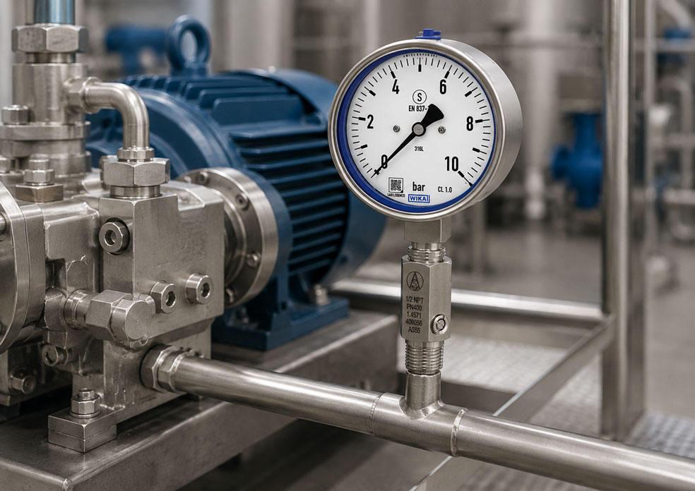
If the pointer of a pressure gauge vibrates heavily, oscillates across a large part of the scale or regularly strikes the end stop, the measuring instrument itself is often not defective. Piston pumps, diaphragm pumps, dosing pumps, compressors and certain hydraulic power units generate pulsating pressure profiles as a result of their design.
This subjects the pressure gauge to high dynamic loads. The Bourdon tube, movement, bearings and gearing are continuously accelerated and decelerated. The indication becomes difficult to read, while the movement may wear prematurely or be permanently damaged by short pressure spikes.
A liquid filling inside the case can stabilise the pointer. However, it does not automatically eliminate the pressure pulsation at the process connection. Stronger pulsations additionally require restrictor bores, pressure snubbers or other process-side damping elements.
It is therefore essential to distinguish between pressure pulsation, pressure spikes and mechanical vibration. Only then can it be determined whether a liquid-filled pressure gauge, snubber, capillary line, alternative measuring point or a combination of several measures is required.
Suitable measuring instruments can be found in the pressure gauges and digital pressure gauges category. Restrictors, snubbers, shut-off valves and other protective components are grouped together under accessories for pressure measuring instruments.
Contents
- What is pressure pulsation?
- Distinguishing between pulsation, pressure spikes and mechanical vibration
- Why do pulsations damage pressure gauges?
- Which pumps and systems cause pulsations?
- What does a glycerine or silicone-oil filling achieve?
- How does a restrictor bore work?
- When is a pressure snubber required?
- Can a capillary line damp pressure?
- When must pulsation be reduced within the process?
- Selecting the correct measuring range and overload protection
- Selecting the correct installation point
- Which type of damping matches which fault pattern?
- Correctly adjusting an adjustable pressure snubber
- Typical damping errors
- Practical example: Pressure gauge on a dosing pump
- Recommended commissioning procedure
- Which measuring instruments and products are suitable?
- Conclusion
- Frequently asked questions
What is pressure pulsation?
With pressure pulsation, the process pressure fluctuates regularly or irregularly around an average value. The fluctuation may be caused, for example, by the delivery movement of a piston or diaphragm pump. The pressure rises during the delivery stroke and falls again during the suction stroke or when the valves switch.
A mechanical pressure gauge follows these changes through its Bourdon tube and connected pointer movement. If the pulsation frequency is sufficiently low, the pointer visibly moves between the respective pressure values. At higher frequencies, it begins to vibrate or appears as a blurred pointer range.
The average indication may still appear plausible. Nevertheless, the pressure gauge is subjected to considerably greater dynamic loads than under constant pressure. Knowing only the average operating pressure is therefore not sufficient for selecting the instrument.
The following information is also required:
- minimum and maximum pressure within a pump cycle,
- frequency of the pressure fluctuation,
- magnitude and duration of short pressure spikes,
- medium, viscosity and temperature,
- mechanical vibration load at the measuring point,
- required response time of the indication.
Distinguishing between pulsation, pressure spikes and mechanical vibration
A rapidly oscillating pointer can have different causes. These causes must be distinguished because the suitable protective measures are not identical.
| Load | Typical behaviour | Common cause | Suitable measure |
|---|---|---|---|
| Pressure pulsation | Pointer moves regularly between several pressure values | Piston pump, diaphragm pump, compressor or dosing pump | Restrictor, pressure snubber or process pulsation dampener |
| Pressure spike | Short deflection, sometimes reaching the end of the scale | Fast-closing valve, water hammer, cavitation or load change | Pressure snubber, overload protection and suitable measuring range |
| Mechanical vibration | Case and pointer vibrate together | Pump, motor, pipework or machine frame | Case filling, mounting bracket or spatial decoupling |
| Unstable process | Pressure changes slowly and genuinely within the system | Control valve, fluctuating consumption or inadequate pump control | Investigate the process cause instead of merely damping the indication |
A case filling can reduce mechanical vibrations and minor pointer flutter. However, it does not prevent the Bourdon tube from continuing to experience the full pulsating process pressure.
Conversely, a pressure snubber dampens pressure transmission to the gauge but does not protect the case against severe pipe vibrations. On a vibrating pump unit, a combination of a pressure snubber, liquid-filled pressure gauge and mechanically decoupled mounting may therefore be necessary.
Why do pulsations damage pressure gauges?
A Bourdon-tube pressure gauge converts the pressure-dependent deformation of a curved Bourdon tube into a rotary movement through a transmission and pointer mechanism. Under constant pressure, the mechanism remains largely in a fixed position.
Under pulsating pressure, however, the complete system moves continuously. This produces alternating loads on:
- the Bourdon tube and its connection points,
- the link and transmission mechanism,
- gears and toothed segments,
- bearings within the pointer movement,
- the pointer and pointer shaft,
- mechanical end stops.
As the pulsation frequency increases, the number of load cycles also increases. Even if every individual deflection remains within the nominal measuring range, the continuous alternating load can cause increased wear.
The situation becomes particularly critical when the pointer regularly strikes the end of the scale or the mechanical stop. In this case, either the measuring range is too small or pressure spikes are occurring that may only be partially visible on a slowly responding indication.
Typical consequences include:
- poor readability,
- shifted zero point,
- increasing indication error,
- loose or bent pointer,
- worn gearing,
- fatigue or permanent deformation of the Bourdon tube,
- premature failure of the measuring instrument.
Which pumps and systems cause pulsations?
Piston and plunger pumps
Piston pumps deliver the medium in individual strokes. Depending on the number and arrangement of the pistons, pronounced pressure waves can occur. Multi-piston pumps may produce a more uniform flow, but this does not automatically make the pressure completely constant.
Diaphragm and dosing pumps
Diaphragm pumps also deliver the medium in individual strokes. Particularly at low dosing rates and with long pipes, strong pressure fluctuations may occur. Check valves, gas bubbles and changing back pressures additionally influence the pressure profile.
Compressors
Reciprocating compressors generate periodic pressure fluctuations on the suction and discharge sides. These pulsations can be amplified in combination with pipe resonances.
Hydraulic power units
Gear, vane and piston pumps generate flow ripple depending on their design. Fast directional-control valves, load changes and pressure-relief valves can produce additional pressure spikes.
Cavitation and gas bubbles
Cavitation is not a normal pump pulsation. Vapour bubbles form and collapse within the medium. This can produce high-frequency pressure shocks, noise and damage to the pump, valves and measuring instruments.
Strong damping of the pressure gauge may reduce visible pointer oscillation, but it does not eliminate the cause of cavitation. The suction line, inlet pressure, temperature, filters, valves and pump sizing must be checked separately.
What does a glycerine or silicone-oil filling achieve?
In a liquid-filled pressure gauge, a damping fluid is contained inside the case. As a result, the pointer movement no longer moves freely in air but within a viscous liquid.
The filling performs several functions:
- stabilisation of the pointer movement,
- reduction of visible pointer flutter,
- damping of mechanically transmitted vibrations,
- lubrication of moving components,
- protection of the interior against condensation and contamination,
- improved readability in unstable environments.
A glycerine-water mixture is frequently used. Silicone oils may be selected for different ambient temperatures or special applications. The permissible temperature ranges and material compatibility must be checked for the specific instrument version.
For oxygen, strong oxidising agents or special hygienic and safety requirements, a standard pressure gauge with an arbitrary filling must not be used. Only expressly approved and appropriately cleaned versions may be installed.
Why is the case not completely filled?
Liquid-filled pressure gauges often have a visible air or gas space. This allows the filling liquid to expand as the temperature changes. A small unfilled area is therefore not an indication of incomplete or defective filling.
Observe pressure equalisation of the case
On many liquid-filled pressure gauges, a pressure-equalisation opening or venting plug must be opened after installation in accordance with the manufacturer’s instructions. If the case remains completely sealed, temperature changes can create internal pressure and influence the zero point.
Limitations of case filling
The filling primarily dampens the movement of the pointer mechanism. The pulsating pressure load continues to reach the Bourdon tube. For strong pressure pulsations, a case filling is therefore not sufficient as the only protective measure.
How does a restrictor bore work?
A restrictor bore is located between the process and the pressure gauge. Due to its small free cross-section, the pressure on the instrument side cannot change arbitrarily quickly. Rapid pressure changes are reduced and delayed over time.
Possible restrictor elements include:
- a small bore in the connection channel,
- a replaceable restrictor screw,
- a capillary insert,
- a porous sintered element,
- an adjustable needle.
The effect depends on several factors:
- cross-section and length of the restriction channel,
- viscosity and density of the medium,
- pulsation frequency,
- rate of pressure change,
- volume on the measuring-instrument side,
- temperature of the medium.
Does the restrictor cause a pressure loss?
A pressure gauge is normally installed at the end of a measuring line in which no continuous flow takes place. After a sufficiently long equalisation period, the pressure gauge therefore generally indicates the static process pressure.
During a pressure change, however, a temporary pressure difference exists across the restrictor. The pressure gauge responds with a delay and indicates rapid spikes only in an attenuated form. This delay is the intended damping effect.
If the restrictor is too small or partially blocked, the pressure gauge may respond very slowly even to normal process changes. A leak on the instrument side can additionally produce a permanent measurement error.
When is a pressure snubber required?
A pressure snubber is a separate accessory installed between the process connection and the pressure gauge. It contains a defined flow resistance that prevents rapid pressure changes from reaching the measuring instrument directly.
A pressure snubber is particularly useful when:
- the pointer continues to oscillate strongly despite a case filling,
- regular pressure pulsations occur,
- short pressure shocks load the movement,
- the pressure gauge repeatedly fails prematurely,
- an integrated restrictor is not available or is insufficient,
- the damping must be adapted to the process.
Fixed pressure snubber
Fixed versions have a predefined restriction cross-section. They are compact and require no adjustment. However, their design must match the medium, viscosity and pulsation.
A version that works well with low-viscosity hydraulic oil may provide excessive damping or become blocked with a highly viscous medium. Conversely, a restrictor designed for viscous oil may provide insufficient damping with gas or water.
Adjustable pressure snubber
With adjustable versions, the free cross-section is altered using a needle or valve element. This allows the indication to be adapted to the actual pulsation during commissioning.
This design is useful for:
- changing operating conditions,
- unknown pulsation intensity,
- different medium viscosities,
- variable pump speeds,
- dosing systems with different recipes.
A pressure snubber is not overload protection
A pressure snubber reduces the speed and amplitude of short pressure changes at the pressure gauge. However, a continuously excessive process pressure is still transmitted in full after pressure equalisation.
If the process pressure can continuously exceed the permissible measuring range, suitable overload protection or a larger measuring range is additionally required.
Can a capillary line damp pressure?
A long or narrow measuring line can also provide a damping effect. The flow resistance of the line and the volume between the process and the measuring instrument delay pressure transmission.
Capillary lines are mainly used to:
- move the pressure gauge away from a vibrating machine,
- keep high process temperatures away from the instrument,
- position the display at a more accessible location,
- reduce mechanical loads on the process connection.
The damping effect of a capillary should not occur by chance but should be technically assessed. A very long or very narrow line can significantly delay the indication.
Other possible problems include:
- trapped gas bubbles in liquid lines,
- condensate in gas lines,
- temperature-dependent viscosity,
- blockage caused by particles or deposits,
- mechanical damage to the line,
- additional potential leakage points.
If the pressure gauge merely needs to be mechanically isolated from the pump, a suitable measuring line with a stable mounting arrangement may be useful. For reproducible pulsation damping, however, a defined pressure snubber is usually easier to adjust.
When must pulsation be reduced within the process?
A pressure snubber in the gauge connection primarily protects the measuring instrument. The pressure pulsation remains present in the main process line. If valves, seals, pipes or dosing equipment are also affected by the pulsation, the problem must be reduced within the process itself.
Suitable measures may include:
- pulsation dampeners,
- diaphragm or bladder accumulators,
- air vessels,
- adapted pump speed,
- several pump heads operating with a time offset,
- optimised valve control,
- adapted pipe routing.
A process pulsation dampener stores part of the delivery volume during a pressure peak and releases it again when the pressure falls. This smooths not only the pressure-gauge indication but also the actual pressure profile within the line.
For strong pulsations, the following combination is often useful:
- pulsation dampener in the main process line,
- pressure snubber directly upstream of the pressure gauge,
- liquid-filled pressure gauge for additional mechanical pointer damping.
Selecting the correct measuring range and overload protection
An undersized measuring range is a common cause of pressure-gauge damage. The decisive value is not only the visible average operating pressure, but the highest pressure actually occurring, including pulsation and pressure spikes.
The normal operating pressure should remain sufficiently below the scale end value. Under dynamic loads, stricter load limits generally apply than under constant pressure. The permissible static and dynamic loads must therefore be checked against the manufacturer’s specifications for the specific pressure gauge.
An unnecessarily large measuring range is also disadvantageous. If a process operating at approximately 6 bar is monitored using a pressure gauge with a range up to 100 bar, the instrument may be protected against many pressure spikes, but small process changes are difficult to recognise.
The following must be considered when selecting the measuring range:
- minimum and normal operating pressure,
- maximum pressure within the pulsation,
- possible start-up and shutdown spikes,
- opening pressure of safety or pressure-relief valves,
- permissible overload of the pressure gauge,
- required readability,
- possible future operating conditions.
First make pressure spikes visible
A mechanical pressure gauge may not fully indicate very short pressure spikes. For diagnostic purposes, a suitable digital or test pressure gauge with minimum/maximum or peak function can be used temporarily.
The reference instrument itself must be suitable for the expected pressure spikes, pulsation frequency and medium. A high display resolution alone does not mean that extremely short pressure spikes will be reliably detected.
Selecting the correct installation point
The installation point has a significant influence on the load applied to the pressure gauge. Pulsations are often particularly strong directly at the pump outlet. Downstream of a pulsation dampener, pressure accumulator or sufficiently sized pipe section, the pressure profile may be more stable.
The following should be checked when selecting the measuring point:
- How far is the measuring point from the pump outlet?
- Are valves, nozzles or changes in cross-section located directly upstream?
- Is a pulsation dampener installed in the main line?
- Is the pressure gauge subjected to pipe or machine vibrations?
- Can air or condensate accumulate in the measuring line?
- Is the measuring point accessible for maintenance and shut-off?
- Does the temperature at the installation point comply with the instrument limits?
The pressure gauge should be installed without mechanical stress. The case must not be used to tighten the process connection. For heavy instruments, long accessory assemblies or strongly vibrating pipes, an additional mounting bracket should be provided.
At high process temperatures, siphons, cooling elements or spatially separated installation may be required. A pressure snubber does not replace suitable temperature protection.
Which type of damping matches which fault pattern?
| Fault pattern | Suitable measure | Important limitation |
|---|---|---|
| Minor pointer flutter | Liquid-filled pressure gauge | Strong process pulsations still reach the Bourdon tube |
| Strong periodic pointer movement | Pressure snubber or restrictor | Response time must not become excessively slow |
| Unknown or changing pulsation | Adjustable pressure snubber | The setting must be secured against unintended adjustment |
| Strong mechanical vibration | Case filling and remote installation | A pressure snubber alone does not mechanically isolate the case |
| Short, high pressure spikes | Pressure snubber, suitable measuring range and overload protection | Pressure spikes must first be reliably determined |
| Permanent overpressure possible | Overload protection device or alternative measuring range | A restrictor does not protect against continuous overpressure |
| The process line itself is dynamically loaded | Pulsation dampener in the main line | A pressure-gauge snubber protects only the measuring branch |
| Viscous or contaminated medium | Cleanable, adjustable pressure snubber or suitable diaphragm seal | Small fixed bores can become blocked |
Correctly adjusting an adjustable pressure snubber
The correct setting is a compromise between a stable indication and an adequate response speed. The pressure gauge should not fully follow rapid, damaging pressure changes, but it must continue to indicate normal process changes.
A suitable procedure is:
- Depressurise the measuring point and install the pressure snubber in accordance with the manufacturer’s instructions.
- Initially set the pressure snubber to a defined open or medium starting position.
- Start the system in a controlled manner.
- Gradually increase the damping until the pointer is easy to read.
- Initiate a normal pressure change in the system and check the response time.
- Shut down the system and check whether the pressure gauge reliably returns to its initial value.
- Secure the setting against unintended adjustment.
The pressure snubber must not be closed completely without this being noticed. Otherwise, pressure may remain trapped inside the gauge. The instrument would then continue to display an outdated value even after the process pressure has changed.
At safety-related measuring points, a heavily damped local indication must not be used as the sole protective or shutdown device. The permissible delay must be appropriate for the function of the measuring point.
Typical damping errors
| Error | Consequence | Corrective action |
|---|---|---|
| Only a liquid-filled pressure gauge is installed | The pointer becomes more stable, but the Bourdon tube remains exposed to strong pulsating loads | Use an additional pressure snubber for strong pulsations |
| Restrictor opened too far | Pointer continues to oscillate strongly | Increase damping gradually |
| Restrictor closed too far | Indication responds too slowly or remains stationary | Increase the cross-section and check the return to zero |
| Fixed restrictor used with a viscous medium | Extremely slow indication or blockage | Select a cleanable or adjustable version suitable for the medium |
| Pressure snubber treated as overload protection | Continuous overpressure still reaches the pressure gauge | Provide additional overload protection or a larger measuring range |
| Case vent not opened | Temperature-dependent zero-point shift | Establish pressure equalisation according to the manufacturer’s instructions |
| Measuring range selected only according to the average pressure | Pressure spikes overload the instrument | Determine the maximum and peak pressure |
| Pressure gauge installed directly on the vibrating pump housing | Mechanical vibration remains despite the pressure snubber | Install the pressure gauge remotely with a stable mounting arrangement |
| Blocked pressure snubber is readjusted | The fault is concealed and the indication becomes increasingly unreliable | Clean or replace the component and investigate the cause of contamination |
| Pulsation is damped only at the indication | Pipes and fittings remain dynamically loaded | Consider an additional pulsation dampener within the process |
Practical example: Pressure gauge on a dosing pump
A diaphragm dosing pump delivers a low-viscosity liquid against a process pressure of approximately 6 bar. The existing pressure gauge has a measuring range of up to 10 bar. During every delivery stroke, the pointer oscillates between approximately 4 and 9 bar.
After a short operating period, the zero point changes. The pressure gauge is replaced with a liquid-filled version. The indication initially appears more stable, but another zero-point error occurs after several weeks.
During a comparison measurement with a fast-response digital pressure gauge, short pressure values above the scale end value of the original pressure gauge are detected. The mechanical instrument was therefore exposed not only to visible pulsation, but also to previously undetected pressure spikes.
The measuring point is then systematically modified:
- The cause of the strong pulsation is investigated at the pump and check valves.
- A pulsation dampener matched to the delivery volume and pressure is installed in the main line.
- The pressure gauge is positioned downstream of the process dampener.
- An adjustable pressure snubber is installed directly upstream of the pressure gauge.
- The measuring range is redefined according to the actual peak pressure.
- A liquid-filled pressure gauge is used for additional pointer and vibration damping.
The pressure snubber is adjusted so that the pointer fluctuates only slightly while a slow change in dosing pressure can still be recognised without excessive delay.
This example shows why a case filling alone is not always sufficient. It improves readability, while the process pulsation dampener and pressure snubber reduce the dynamic pressure load. The correctly selected measuring range additionally protects against overload.
Recommended commissioning procedure
- Record the average operating pressure and the minimum and maximum process pressures.
- Distinguish between pulsation, individual pressure spikes and mechanical vibration.
- If necessary, check the peak pressure using a suitable fast-response measuring instrument.
- Check the measuring range and permissible dynamic load of the pressure gauge.
- Assess the medium, viscosity, temperature and contamination.
- Determine whether the pulsation affects only the pressure gauge or the complete system.
- Provide a suitable process pulsation dampener if the main line is affected.
- Select the case filling for mechanical vibration and pointer stabilisation.
- Select a fixed or adjustable pressure snubber suitable for the medium.
- Position the measuring point downstream of the process dampener wherever possible.
- Install the pressure gauge without mechanical stress and mechanically isolate it if required.
- Adjust the damping gradually and check the normal response time.
- Check the return to zero after depressurisation.
- Check all connections for leaks.
- Document the settings and initial condition for future maintenance.
Which measuring instruments and products are suitable?
Pressure gauges and digital pressure gauges
The pressure gauges and digital pressure gauges section contains mechanical and electronic pressure measuring instruments for different measuring ranges, media and accuracy requirements.
Depending on the application, liquid-filled industrial or stainless-steel pressure gauges may be suitable for pulsating pressure. The case material, wetted parts, filling liquid, measuring range and safety design must be selected together.
Pressure snubbers for pressure gauges
Pressure snubbers for pressure gauges reduce the transmission of rapid pressure changes to the measuring instrument. Depending on the version, damping is provided by fixed restrictor cross-sections, sintered elements, capillaries or adjustable needle mechanisms.
The selection depends on the pressure range, medium, temperature, viscosity, pulsation frequency and required response time. For contaminated or viscous media, cleanability and the risk of blockage are particularly important.
Accessories for pressure measuring instruments
The accessories for pressure gauges, diaphragm seals, transmitters and sensors category includes shut-off valves, pressure-gauge cocks, overload-protection devices, adapters, cooling elements and siphons in addition to pressure snubbers.
The components must not be selected in isolation. Thread type, sealing principle, pressure rating, material, temperature and medium must be compatible throughout the complete measuring point.
Digital and test pressure gauges for diagnostics
A suitable digital or test pressure gauge can be used to investigate minimum and maximum values and, depending on the model, rapid pressure profiles. This helps when selecting the correct measuring range and distinguishing between pulsation and individual pressure spikes.
A digital measuring instrument must also be protected against overload and impermissible pressure shocks. A digital display does not automatically eliminate the dynamic load applied to the internal pressure sensor.
Conclusion: Case filling and pressure snubbers perform different functions
A rapidly oscillating pressure-gauge pointer indicates dynamic loads and should not be regarded merely as an inconvenient display problem. Regular pulsations and short pressure spikes can cause premature wear of the movement and permanently shift the zero point.
A glycerine or silicone-oil filling stabilises the pointer movement and protects against mechanical vibration. However, it does not automatically reduce the complete pressure pulsation applied to the Bourdon tube.
A restrictor or pressure snubber acts on the process side. Rapid pressure changes are transmitted to the pressure gauge with a delay. However, the damping must not be so strong that normal process changes, pressure drops or system shutdowns are indicated only after a significant delay.
If continuous overpressure is possible, an overload-protection device or a larger measuring range is additionally required. If the pulsation affects not only the pressure gauge but also pipes, valves and seals, a suitable pulsation dampener should be installed in the main process line.
A reliable measuring point therefore often results from several coordinated measures: a suitable installation point, adequate measuring range, process pulsation dampener, pressure snubber and liquid-filled pressure gauge.
Frequently asked questions about pressure gauges under pulsating pressure
Is a glycerine-filled pressure gauge sufficient for a pulsating pump?
For minor pulsations and mechanical vibrations, the filling may be sufficient. If the pointer oscillates across a large part of the scale or pressure spikes occur, an additional pressure snubber should be installed.
What is the difference between a pressure snubber and a pulsation dampener?
A pressure snubber is normally installed directly upstream of the pressure gauge and primarily protects the measuring instrument. A pulsation dampener is installed in the main line and smooths the actual pressure or delivery flow within the system.
Does a pressure snubber change the indicated pressure?
After sufficient pressure equalisation, the pressure gauge generally indicates the static process pressure. Rapid pressure changes are transmitted with a delay and reduced amplitude. If the restriction is excessive or blocked, the indication may respond unacceptably slowly.
Does a pressure snubber protect against continuous overpressure?
No. Continuous overpressure is transmitted in full to the pressure gauge after pressure equalisation. A suitable measuring range or additional overload-protection device is required for this purpose.
When is an adjustable pressure snubber useful?
It is particularly suitable for changing pump speeds, different media, unknown pulsation intensity or varying operating conditions. The damping can be adapted during commissioning.
Why does the pressure gauge return to zero only slowly after shutdown?
Possible causes include an excessively closed restrictor, blocked bore, trapped pressure, long measuring line or damaged movement. The pressure snubber and measuring line should be checked first.
Why does a liquid-filled pressure gauge show a different zero point when the temperature changes?
One possible cause is missing pressure equalisation of the case. The filling liquid expands as the temperature rises and creates internal pressure in a completely sealed case. The vent must be adjusted in accordance with the manufacturer’s instructions.
Can a long measuring line replace a pressure snubber?
A long or narrow line can have a damping effect, but this effect depends strongly on its length, diameter, medium, temperature and trapped gas bubbles. A suitable pressure snubber is generally preferable for defined and adjustable damping.
How can I tell whether the measuring range is too small?
If the pointer regularly moves into the upper part of the scale or strikes the end stop, the actual peak pressure must be checked. Very short pressure spikes may remain invisible on a mechanical pressure gauge and require a suitable faster comparison measurement.
Are digital pressure gauges insensitive to pulsations?
Digital pressure gauges have no mechanical pointer movement, but their pressure sensor is still subjected to pulsations and pressure spikes. Electronic instruments also require a suitable measuring range and, where necessary, a pressure snubber or overload protection.