


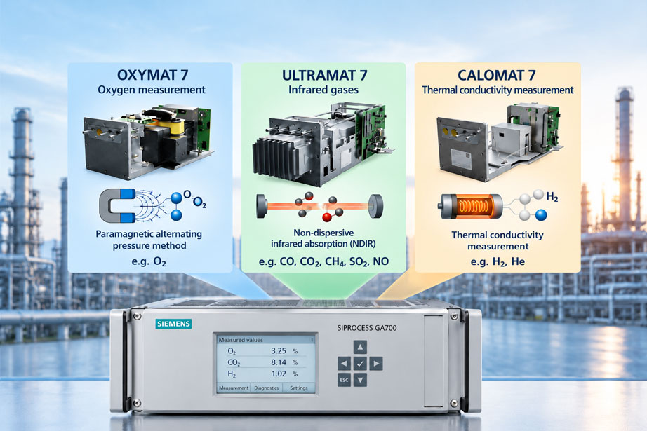
A gas analyzer can only provide reliable process information if its measuring principle is suited to the chemical composition of the sample gas. In industrial plants, several gas components often need to be measured simultaneously: for example, oxygen and carbon monoxide in a combustion plant, carbon dioxide in a chemical process, or hydrogen in a protective gas mixture.
The Siemens SIPROCESS GA700 provides a modular platform for continuous extractive process gas analysis. The analyzer modules OXYMAT 7, ULTRAMAT 7 and CALOMAT 7 are based on different physical measuring principles. This allows various measurement tasks to be performed within one device family and, where approved for the respective device configuration, several measuring principles to be combined in one basic unit.
However, selecting a suitable module does not begin with the device designation. The primary factors are the target components, their expected concentrations, the composition of the background gas, possible cross-interferences, and the physical properties of the sample gas.
A typical problem arises, for example, when a thermal conductivity analyzer is intended for hydrogen measurement even though several background gases fluctuate independently of one another. In this case, it is not only the hydrogen concentration that changes the thermal conductivity of the mixture. Changes in the other gas components can also affect the measurement result.
Likewise, it is not sufficient to select two suitable analyzer modules and assume that they can be installed together mechanically. Certain GA700 module combinations are subject to additional restrictions regarding measuring frequency, permissible ambient temperature, measuring range, or electromagnetic compatibility.
This technical article explains the three measuring principles, the selection of suitable module combinations, and the application-specific configuration of the SIPROCESS GA700. It also covers sample gas conditioning, interfaces, parameterization, adjustment, diagnostics, and systematic commissioning.
Table of Contents
- Define the Measurement Task Before Selecting the Module
- Understand the Design and Function of the SIPROCESS GA700
- Physical Measuring Principles of the Three Analyzer Modules
- Compare OXYMAT 7, ULTRAMAT 7 and CALOMAT 7
- Consider Gas Composition and Cross-Sensitivities
- Define Sample Gas Conditioning and Installation Conditions
- Determine Measuring Ranges and Device Configuration
- Practical Example: Designing a Multicomponent Gas Analysis System
- Check Permissible Module Combinations and Restrictions
- Selecting OXYMAT 7 for Oxygen Measurement
- Selecting ULTRAMAT 7 for Infrared-Active Gases
- Selecting CALOMAT 7 for Hydrogen and Thermal Conductivity Measurement
- Plan Gas Routing and the Integration of Multiple Measurement Tasks
- Use Reference Gases, Zero Gases and Test Gases Correctly
- Integrate Interfaces and Process Automation
- Configure Measuring Ranges, Outputs and Functions
- Adjustment, Reference Measurement and Measurement Uncertainty
- Use Diagnostic Values and Preventive Maintenance
- Explosion Protection, Process Safety and Operating Conditions
- Systematic Testing and Commissioning Procedure
- Typical Fault Symptoms and Targeted Diagnostics
- Suitable Siemens Products from ICS Schneider Messtechnik
- Conclusion: Select the Measuring Principle and Module Configuration Together
- Frequently Asked Questions About the SIPROCESS GA700
1. Define the Measurement Task Before Selecting the Module
Every device selection begins with the question of which gas component must be measured, with what accuracy, and under which operating conditions.
For industrial gas analysis, at least the following parameters should be known:
- Target components: Which gases must be measured quantitatively, for example O₂, CO, CO₂, CH₄ or H₂?
- Measuring ranges: Which concentrations occur during normal operation, and what maximum values are possible?
- Background gases: Which other gases are present in the mixture, and how significantly do their concentrations fluctuate?
- Sample gas conditions: What temperatures, pressures, humidity levels and particle loads are present at the sampling point?
- Dynamic response: How quickly must a change in concentration be detected?
- Installation environment: Will the device be installed in an analyzer cabinet, a protected operating room or a hazardous area?
- Process integration: Which analog signals, digital status messages and communication protocols are required?
- Measurement purpose: Is the result used for process optimization, quality control, emissions monitoring or a safety-related application?
This information determines not only the analyzer module but also the entire measurement chain, from gas sampling to evaluation in the process control system.
A gas analyzer that offers high accuracy for a particular measuring range is not automatically suitable for every gas mixture. The chemical composition and possible cross-sensitivities must always be part of the technical design.
2. Understand the Design and Function of the SIPROCESS GA700
The Siemens SIPROCESS GA700 is a modular device platform for continuous extractive gas analysis. The system consists of a basic unit and at least one analyzer module.
The basic unit performs the following tasks in particular:
- Electrical power supply and connection of the installed analyzer modules.
- Processing of measured values and internal operating data.
- Display of concentrations, measuring ranges and device status.
- Parameterization and adjustment via the local user interface.
- Provision of control and communication interfaces.
- Integration of additional configuration-dependent interface modules.
Up to two analyzer modules can be used in wall-mounted and rack-mounted devices. Depending on the configuration, additional interface modules are also available.
The basic unit is available, among other versions, as a 19-inch rack-mounted device with three height units and as a wall-mounted device. Separate device versions are available for certain hazardous-area applications.
However, the mechanical modularity does not mean that every conceivable combination can be operated without restrictions. The approved configuration, the respective operating conditions and the associated Siemens documentation are decisive.
A particular feature is the separation between the device platform and the actual physical analysis method. If, for example, an additional gas component needs to be measured, it must first be checked whether a second module can be installed in the existing basic unit and whether this makes technical sense.
For applications involving more analysis tasks than one basic unit can accommodate, several analyzers are required. These can subsequently be combined into a common measuring station at the process automation level.
3. Physical Measuring Principles of the Three Analyzer Modules
3.1 Paramagnetic Alternating Pressure Method – OXYMAT 7
Oxygen has pronounced paramagnetic properties and is therefore attracted by a magnetic field. The OXYMAT 7 uses this physical effect to determine the oxygen concentration.
Inside the analyzer, the interaction between sample gas, reference gas and magnetic field generates an alternating pressure that depends on the concentration. This pressure is detected by a microflow sensor and converted into an oxygen measurement value.
The actual microflow sensor is located in the reference gas path and does not come into direct contact with the sample gas. This is a design advantage, particularly with demanding sample gas compositions.
The OXYMAT 7 measures oxygen concentration and is not a general multicomponent analyzer for arbitrary gases.
3.2 Non-Dispersive Infrared Measurement – ULTRAMAT 7
The ULTRAMAT 7 operates according to the non-dispersive infrared principle, abbreviated NDIR. Certain gas molecules absorb infrared radiation in characteristic spectral ranges.
The analyzer uses this absorption to determine concentration. The dual-beam alternating-light method with a selective detection principle enables the measurement of suitable infrared-active components.
Typical measured components include CO, CO₂, CH₄, SO₂, NO and other gases specified for the respective module.
Depending on the ordered configuration, one ULTRAMAT 7 module can measure up to two components. However, this does not mean that any arbitrary combination of two gases is possible.
3.3 Thermal Conductivity Measurement – CALOMAT 7
The CALOMAT 7 determines gas composition based on differences in thermal conductivity.
A micromechanical sensor with a temperature-controlled measuring structure responds to heat transfer from the surrounding sample gas. The electrical power required for temperature control depends on the thermal conductivity of the gas mixture.
For a known binary gas mixture, this effect can be used to determine the concentration of one component.
Particularly typical applications include the measurement of hydrogen or helium in suitable background gases.
Since thermal conductivity is not a property that is specific exclusively to one individual gas component, additional or fluctuating background gases can influence the measurement result.
4. Compare OXYMAT 7, ULTRAMAT 7 and CALOMAT 7
The analyzer modules differ primarily in their physical measuring methods, the components they can measure, and their sensitivity to changes in the background gas.
| Feature | OXYMAT 7 | ULTRAMAT 7 | CALOMAT 7 |
|---|---|---|---|
| Measuring principle | Paramagnetic alternating pressure method | Non-dispersive infrared absorption | Thermal conductivity measurement |
| Typical measured components | O₂ | CO, CO₂, CH₄, SO₂, NO and other specified IR-active gases | H₂, He and other suitable gases in binary or quasi-binary mixtures |
| Typical application | Oxygen monitoring, combustion control, gas purity measurement | Combustion and process gas analysis, chemical processes | Hydrogen monitoring, protective gas and high-purity gas monitoring |
| Main influencing factors | Reference gas, pressure, gas composition, vibrations | Overlapping absorption bands, interfering gases, optical gas path | Thermal conductivity and composition of the background gas |
| Special requirement | Suitable reference gas supply | Suitable and selective IR measurement component | Known and sufficiently stable gas composition or validated correction |
| Important selection limitation | Not a substitute for CO or CO₂ analysis | No direct NDIR measurement of O₂, N₂ or H₂ | No component-specific multicomponent analysis with arbitrarily fluctuating mixtures |
A sensible first step in the selection process is therefore to assign the target components to the appropriate measuring principle.
The OXYMAT 7 is intended for oxygen. The ULTRAMAT 7 is suitable for appropriate infrared-active gases. The CALOMAT 7 offers advantages when the concentration of a gas can be determined using a sufficiently distinct difference in thermal conductivity.
The measuring range, background gases, sample gas conditioning and module combination must then be considered.
5. Consider Gas Composition and Cross-Sensitivities
The target component alone does not fully describe a measurement task. The other gases present are also relevant when selecting the analysis method.
5.1 Cross-Sensitivity of OXYMAT 7
With the paramagnetic method, the measuring signal is primarily generated by the special magnetic properties of oxygen.
However, other gas components can still influence the measurement. These effects include changes in the magnetic properties of the gas mixture as well as changes in physical measurement conditions.
For this reason, the actual gas composition and any necessary cross-interference corrections must be taken into account.
5.2 Cross-Sensitivity of ULTRAMAT 7
In infrared measurement, the absorption ranges of different gases can overlap. An additional infrared-active gas can therefore contribute to the measuring signal even though it is not the actual target component.
The ULTRAMAT 7 offers options for cross-interference correction. Whether these are sufficient for the application depends on the gases involved, their concentration ranges and the configured device version.
It is also important whether the concentration of an interfering background gas is constant or varies independently.
5.3 Cross-Sensitivity of CALOMAT 7
Fluctuating background gases are particularly critical in thermal conductivity measurement.
A CALOMAT 7 can, for example, measure hydrogen in nitrogen if the mixture composition is suitable for the intended measurement task.
If the concentrations of carbon dioxide or methane also change independently, the thermal conductivity changes even without a corresponding change in hydrogen concentration.
Without suitable compensation, the analyzer could interpret this change at least partially as a change in the target gas concentration.
Crucial point: Cross-interference correction is no substitute for complete knowledge of the gas mixture. It must be technically designed for the expected concentrations and verified through suitable reference measurements.
6. Define Sample Gas Conditioning and Installation Conditions
The SIPROCESS GA700 platform is designed for extractive gas analysis. This means that the sample gas is taken from the process, conditioned if necessary, and then passed through the analysis system.
Sample gas conditioning must ensure that temperature, pressure, humidity, contamination and flow rate remain within the permissible limits of the respective module.
6.1 Particles and Contamination
Particles can contaminate gas lines, filters, restrictors or measuring chambers. This changes flow conditions and potentially the optical properties of the gas path.
Suitable particle filtration is therefore particularly important for process gases with high dust loads.
6.2 Humidity and Condensation
Liquid condensate must not enter the analyzer modules in an uncontrolled manner.
Depending on the measurement task, heated sampling lines, sample gas coolers or suitable water separators may be used, for example.
However, drying can change the gas composition under certain circumstances. Water-soluble target components, in particular, may be partially lost during cooling and condensation.
Sample gas conditioning must therefore not only protect the device but also transport the components to be measured to the analyzer with as little alteration as possible.
6.3 Sample Gas Pressure and Flow Rate
Excessively high or low sample gas pressure can impair operation. In addition, leaks under negative pressure can cause ambient air to enter the gas path.
The required sample gas flow rate must be determined based on the specific modules and their gas path variants.
When several modules are used, it must also be checked whether the gas paths may be operated in parallel or in series and how this affects pressure loss and response time.
6.4 Installation and Ambient Conditions
When choosing between rack-mounted and wall-mounted enclosures, the available installation space, ambient temperature, degree of protection, accessibility and possible mechanical vibrations must be considered.
Ease of maintenance is also important: filters, gas connections, electronics and modules must remain safely accessible.
7. Determine Measuring Ranges and Device Configuration
A suitable measuring range covers all concentrations relevant to the measurement task. A distinction must be made between the normal operating range, possible process deviations and the maximum expected concentration.
For example, a plant may have an oxygen concentration of 3 to 8 vol.% under normal conditions, while significantly higher values may occur during a malfunction.
If only a very small measuring range is selected, such operating conditions may fall outside the intended measurement span.
Conversely, an unnecessarily large measuring range may be unfavorable for the required resolution and measurement uncertainty at low concentrations.
In suitable configurations, the SIPROCESS GA700 supports several configurable measuring ranges as well as automatic or remotely controlled measuring range switching.
The following aspects must be considered when determining the required configuration:
- Minimum and maximum concentration of the target component.
- Required absolute or relative measurement uncertainty.
- Required detection limit and measurement span.
- Expected short-term concentration peaks.
- Influence of background gases and cross-interference corrections.
- Behavior of the output signal during overrange conditions or faults.
- Requirements for measuring range switching and scaling in the control system.
It is particularly important to distinguish between a freely configurable measuring range and the actual metrologically specified measuring range of the installed module.
Changing the display or output scaling cannot extend the physical capabilities of a sensor.
8. Practical Example: Designing a Multicomponent Gas Analysis System
An industrial combustion plant requires continuous monitoring of oxygen and carbon dioxide. The operator also needs to know how quickly concentration changes at the process sampling point can be detected by the analyzer.
8.1 Initial Situation
The following explicitly selected project assumptions are used for this calculation example:
- Target component 1: O₂ in the range of 0 to 25 vol.%.
- Target component 2: CO₂ in the range of 0 to 12 vol.%.
- Selected measuring principles: OXYMAT 7 for O₂ and ULTRAMAT 7 for CO₂.
- Sampling line: length 12 m, internal diameter 4 mm.
- Flow rate: 1.0 liter per minute as the actual volumetric flow rate under the considered line conditions.
- Additional effective gas volume: 0.25 liters as an example.
- Example concentrations: 8 vol.% O₂ and 3 vol.% CO₂.
- Example analog outputs: 4 to 20 mA.
The concentrations, dimensions and flow rates are calculation values and do not represent guaranteed product-specific operating data.
8.2 Calculate the Gas Volume of the Sampling Line
The internal volume of a cylindrical sampling line is calculated as follows:
V = π · d² / 4 · L
With an internal diameter of d = 0.004 m and a line length of L = 12 m, this gives:
V = π · (0.004 m)² / 4 · 12 m
V = 0.0001508 m³ = 0.1508 liters
At a volumetric flow rate of 1.0 liter per minute, the calculated mean transport time for the line is:
t = V / Q
t = 0.1508 l / (1.0 l/min)
t = 0.1508 min = 9.05 s
In addition, an effective gas volume of 0.25 liters is assumed in this example.
The total volume considered is therefore:
V total = 0.1508 l + 0.25 l = 0.4008 l
The corresponding calculated volume exchange time is:
t = 0.4008 l / (1.0 l/min) · 60 s/min = 24.05 s
These approximately 24 seconds are not an exact prediction of the T90 value of the complete measurement chain. Additional mixing processes, flow profiles, sensor response times and the actual volume distribution influence the dynamic response.
A practical step-response test is therefore required to assess the overall system dynamics.
8.3 Scale the Analog Outputs
For linear scaling of a 4-to-20-mA output, the following applies:
I = 4 mA + 16 mA · (c – c min) / (c max – c min)
For an oxygen measuring range of 0 to 25 vol.% and an example concentration of 8 vol.%, the result is:
I = 4 mA + 16 mA · 8 / 25
I = 9.12 mA
For a carbon dioxide measuring range of 0 to 12 vol.% and an example concentration of 3 vol.%, the result is:
I = 4 mA + 16 mA · 3 / 12
I = 8.00 mA
| Calculation parameter | Assumption or formula | Result |
|---|---|---|
| Line length | 12 m | 12 m |
| Internal diameter | 4 mm | 0.004 m |
| Line volume | π · d² / 4 · L | 0.1508 l |
| Additional gas volume | Freely selected example value | 0.25 l |
| Total volume considered | 0.1508 l + 0.25 l | 0.4008 l |
| Volumetric flow rate | 1.0 l/min | 1.0 l/min |
| Calculated volume exchange time | 0.4008 l / 1.0 l/min | 24.05 s |
| O₂ output signal | 8 vol.% at 0 to 25 vol.% | 9.12 mA |
| CO₂ output signal | 3 vol.% at 0 to 12 vol.% | 8.00 mA |
8.4 Technical Interpretation
The example application illustrates two different design tasks.
First, the analyzer modules must be capable of measuring the intended target components and concentration ranges.
Second, the entire gas transport path influences the time between a concentration change in the process and the display of the new measured value.
Even an analyzer module with a very fast response cannot automatically compensate for a long sampling line or one with a large internal volume.
For fast process control, it may therefore be beneficial to shorten the sampling line, reduce dead volumes or use a properly designed bypass arrangement.
When several modules are used, it must also be checked whether both measurement channels detect the same gas composition at the same time and whether different transport times affect the evaluation.
9. Check Permissible Module Combinations and Restrictions
The modular architecture of the SIPROCESS GA700 makes it possible to use different measuring principles within a common system.
The Siemens AP 01 catalog from 2024 describes the possibility of installing a maximum of two analyzer modules in wall-mounted and rack-mounted devices. The current configuration must be verified against the applicable manufacturer documentation and the Siemens configurator.
In principle, various combinations of OXYMAT 7, ULTRAMAT 7 and CALOMAT 7 modules are supported. However, special technical restrictions apply.
9.1 Combination of OXYMAT 7 and ULTRAMAT 7
A typical application is the combined measurement of oxygen and an infrared-active gas component, such as CO₂ or CO.
According to the Siemens catalog, the combination of OXYMAT 7 and ULTRAMAT 7 requires, among other things, different measuring frequencies. Additional restrictions may apply regarding the smallest measuring range and permissible temperature range.
The configured combination must therefore be evaluated as a complete system.
9.2 Combination of ULTRAMAT 7 and CALOMAT 7
This combination may be of interest when, for example, an infrared-active component and hydrogen need to be measured.
According to the Siemens catalog, special restrictions must be observed for such a combination, for example regarding the permissible ambient temperature range. The catalog also states that NAMUR NE 21 does not apply to the combination of CALOMAT 7 and ULTRAMAT 7.
Whether the combination is suitable for a specific plant must therefore be assessed, including the requirements for electromagnetic compatibility.
9.3 Combination of OXYMAT 7 and CALOMAT 7
Such a module configuration may be relevant for applications requiring oxygen and thermal conductivity measurement.
Here too, the Siemens catalog specifies restrictions regarding the applicability of NAMUR NE 21 to the combination.
A mechanically possible module combination is therefore not automatically approved for all operational or regulatory requirements.
9.4 Additional Combinations
Combinations of identical module types are also possible depending on the configuration. For certain combinations, the measuring frequencies must be coordinated according to the manufacturer’s specifications.
Important: Earlier editions of Siemens documentation may contain different assignment or combination rules. For purchasing and installation, the documentation applicable to the specific device, its hardware version and its software version is therefore decisive.
If more than two analyzer modules are required, the measurement task must be distributed across several basic units.
10. Selecting OXYMAT 7 for Oxygen Measurement
The OXYMAT 7 is designed for the quantitative determination of oxygen in suitable gas mixtures.
Typical applications include:
- Monitoring oxygen concentration in combustion processes.
- Process control in chemical plants.
- Quality monitoring in industrial gas mixtures.
- Oxygen purity measurement.
- Monitoring oxygen concentrations in suitable process gases.
The paramagnetic alternating pressure method offers the advantage that the actual microflow detector element is located in the reference gas path.
Nevertheless, the materials in contact with the sample gas must be suitable for the particular gas.
10.1 Selecting the Reference Gas
A suitable reference gas is required for the measuring principle. Its composition and supply pressure depend on the intended configuration and measurement task.
An inadequate reference gas supply can cause measurement deviations or corresponding diagnostic messages.
10.2 Small Measuring Ranges and Oxygen Purity
The OXYMAT 7 is also available for small oxygen measurement spans and measuring ranges with a suppressed zero point.
However, a measuring range close to 100 vol.% oxygen has different requirements from monitoring low oxygen concentrations in a process gas.
The measuring range, reference gas and required accuracy must be considered together.
10.3 Vibrations and Pressure Influences
The measuring principle detects very small physical flow and pressure effects. Strong vibrations can therefore act as a source of interference.
Depending on the device configuration, vibration compensation functions are available.
In addition, sample gas pressure and reference gas pressure must remain within the specified limits.
When ordering a specific device, particular attention must be paid to the different gas path and pressure variants.
11. Selecting ULTRAMAT 7 for Infrared-Active Gases
The ULTRAMAT 7 is suitable for measuring gases with characteristic infrared absorption.
Depending on the ordered configuration, these include, among others:
- Carbon monoxide (CO).
- Carbon dioxide (CO₂).
- Methane (CH₄).
- Sulfur dioxide (SO₂).
- Nitric oxide (NO).
- Other specified IR-active components such as N₂O or NH₃.
The method is particularly useful when high selectivity toward other gas components is required.
11.1 Selecting the Measured Component
The measured component is a key characteristic of the module configuration.
An analyzer channel designed for CO₂ cannot automatically be used to measure an arbitrary different gas simply by changing the display unit.
The optical design, detection principle and parameterization must be suitable for the intended component.
11.2 Selecting a Two-Component Module
Depending on its configuration, one ULTRAMAT 7 module can measure up to two components.
When selecting the module, the permissible component combinations, measuring ranges and required selectivity must be checked in particular.
In certain applications, this can make it possible to monitor several infrared-active components using a single module.
11.3 Cross-Interference Correction
In complex gas mixtures, the absorption characteristics of different components can influence one another.
The ULTRAMAT 7 offers application-dependent correction options for this purpose.
These must be configured based on the background gases actually present. Incorrectly configured cross-interference correction can itself cause additional measurement deviations.
11.4 Measuring Chamber Contamination
Contamination can affect optical measurement and cause gradual changes in the measured values.
Certain analyzer cells of the ULTRAMAT 7 can be cleaned on site.
Cleaning must be carried out according to the manufacturer’s instructions. Suitable functional and adjustment checks are required afterward.
12. Selecting CALOMAT 7 for Hydrogen and Thermal Conductivity Measurement
The CALOMAT 7 is used particularly for the quantitative determination of hydrogen or helium in binary or quasi-binary gas mixtures.
The thermal conductivity of hydrogen differs significantly from that of many other technical gases. This difference forms the basis of the concentration measurement.
12.1 Binary Gas Mixtures
In an idealized binary gas mixture, the mixture being considered consists exclusively of two gases.
One example is a mixture of hydrogen and nitrogen.
If the composition is known and the measurement conditions remain sufficiently stable, thermal conductivity can be used to determine the concentration.
12.2 Quasi-Binary Gas Mixtures
Quasi-binary mixtures may contain additional gas components whose influence on the measurement must be considered.
The decisive factor is whether the background gas has sufficiently constant thermal conductivity or whether changes can be measured and compensated for.
A fluctuating multicomponent gas mixture can make evaluation considerably more difficult.
12.3 Example of Hydrogen Measurement
An operator wants to monitor hydrogen in a nitrogen-hydrogen mixture.
If the gas composition is actually limited to these two components, the CALOMAT 7 may be a suitable solution.
If varying amounts of methane, carbon dioxide or other components are also introduced, a new technical assessment is required.
The thermal conductivity of the mixture is then no longer dependent solely on the hydrogen concentration.
12.4 Limitations of Thermal Conductivity Measurement
The CALOMAT 7 is not a universal hydrogen detector for arbitrarily composed gas mixtures.
Before ordering, the possible background gases, their concentration fluctuations and the required measurement uncertainty must therefore be clarified.
The chemical compatibility of the sample gas path must also be considered. For standard configurations, Siemens primarily specifies non-corrosive gas mixtures.
13. Plan Gas Routing and the Integration of Multiple Measurement Tasks
If several gas components are to be measured at the same process location, a distinction must be made between the mechanical module configuration and the actual gas routing.
Installing two modules together in one basic unit does not automatically mean that both modules can use the same sample gas stream without additional piping.
13.1 Parallel Gas Routing
With parallel gas routing, the extracted gas stream is divided between several measurement paths.
One advantage may be that each module can be operated under the pressure and flow conditions suitable for its measurement task.
However, gas flow distribution, leak tightness, filtration and potentially different transport times must be considered.
13.2 Series Gas Routing
With series gas routing, the sample gas passes through several analyzer modules consecutively.
Whether this is possible depends on the approved gas paths, pressure conditions, internal restrictors and required flow rate.
A series connection must therefore not be assumed to be permissible solely because the modules can be installed mechanically.
13.3 Sample Gas Transport and Synchronization
If different components are used for the same process evaluation, the measured values must be comparable in time.
Different transport times can, for example, result in an oxygen measurement already reflecting the new process condition while a second gas channel is still responding to the previous composition.
During rapid process changes, this can lead to incorrect interpretation of the combined measurement values.
For such applications, the actual transport times and the dynamic response of the entire measurement chain must be verified.
14. Use Reference Gases, Zero Gases and Test Gases Correctly
In gas analysis, the different functions of gases must be clearly distinguished.
14.1 Reference Gas
In the OXYMAT 7, the reference gas is part of the physical measuring principle.
It is not used merely for an occasional functional check but is required for the intended operation of the analyzer.
Gas type, purity, pressure and flow rate, or the specified supply conditions, must be adapted to the particular device configuration.
14.2 Zero Gas
A zero gas is used to provide a defined reference point when checking or adjusting the measurement channel.
The suitable composition depends on the measuring principle and the intended measuring range.
A zero gas condition suitable for CO₂ measurement is not automatically suitable for oxygen measurement with a suppressed zero point.
14.3 Test Gas
A test gas has a known concentration of the relevant measured component and is used for verification or adjustment.
For a meaningful test, the following information in particular must be available:
- Target gas and background gas.
- Certified concentration.
- Specified uncertainty.
- Validity or suitability for use of the test gas.
- Suitable connection and required operating conditions.
With complex gas mixtures, it may be necessary to match the matrix of the test gas as closely as possible to the process gas.
14.4 Adjustment Is Not the Same as Verification
During verification, the deviation of the displayed value from the known reference value is determined.
During adjustment, the device is set to reduce this deviation.
Meaningful documentation should record the results before and, where applicable, after adjustment separately.
15. Integrate Interfaces and Process Automation
The measured values from a process gas analyzer often need to be transmitted to a PLC, a process control system or a higher-level evaluation platform.
The SIPROCESS GA700 offers different interfaces and optional modules for this purpose.
15.1 Analog Measurement Signal Transmission
Depending on the device configuration and installed interface modules, current outputs are available for transmitting the measured concentrations.
Typical signal ranges are 0 to 20 mA and 4 to 20 mA.
For process integration, the measured component, scaling, measuring range switching and behavior in the event of faults must be clearly documented.
For a basic unit with several components, the required number and assignment of analog outputs must be considered when ordering.
15.2 Digital Inputs and Relay Outputs
Depending on the configuration, digital inputs and outputs enable functions such as:
- External measuring range switching.
- Transmission of collective fault messages.
- Signaling of maintenance requirements.
- Limit value messages.
- Integration of external sample gas conditioning functions.
The exact number and function of the inputs and outputs depend on the basic unit and the installed optional modules.
15.3 Ethernet and Communication Protocols
Wall-mounted and rack-mounted devices include an Ethernet interface as part of the basic unit. Depending on the equipment and system integration, different options are available for higher-level communication.
Depending on the application, these include Modbus TCP, for example, as well as other connections implemented through suitable interfaces or communication solutions.
However, the physical presence of an Ethernet interface does not mean that all communication protocols are available without further configuration or additional components.
15.4 SIMATIC PDM and Diagnostic Integration
For suitable device versions, integration into SIMATIC PDM for parameterization and diagnostics is provided.
This is particularly useful for plants with standardized maintenance and servicing procedures.
When planning the project, access rights, network segmentation, the software version used and the availability of the required device descriptions should be considered.
16. Configure Measuring Ranges, Outputs and Functions
After mechanical and electrical installation, the measurement channels must be configured according to the measurement task.
Parameterization is performed using the intended operating functions of the SIPROCESS GA700.
During initial commissioning, the local user interface supports the operator with guided functions.
16.1 Check Measured Components and Measuring Ranges
Before setting limit values and output signals, it must be ensured that the installed analyzer modules and configured measured components correspond to the planned application.
The permissible measuring ranges are then checked and the required operating ranges configured.
16.2 Set Measurement Damping
Configurable damping can stabilize strongly fluctuating measured value displays.
However, it also causes rapid concentration changes to be displayed with a delay or reduced amplitude.
Fast process control therefore requires different settings from long-term monitoring of a slowly changing gas mixture.
Damping must be selected according to the actual process dynamics.
16.3 Alarm Limits and Status Messages
Limit values should not be set solely based on the maximum measuring range.
It is necessary to assess which concentration changes are critical in the respective process and which responses should follow.
Measured value limits, maintenance requirements and technical device faults must be considered separately.
16.4 Scaling in the PLC
The scaling in the control system must match the output signals exactly.
If an analyzer automatically switches its measuring range but the PLC continues to use the previous range, incorrect concentration values will result.
Automatic measuring range switching must therefore either be correctly accounted for in the process automation system or appropriately restricted for the application.
17. Adjustment, Reference Measurement and Measurement Uncertainty
Even a correctly selected analyzer module must be checked regularly for proper metrological performance.
The appropriate test intervals depend on the application, manufacturer specifications, process exposure and quality requirements.
17.1 Use Suitable Reference Gases
The test gas must be suitable for the measured component and measuring range.
For particularly small measuring ranges, the uncertainty of the reference gas can account for a significant proportion of the total test uncertainty.
The concentration of the test gas should therefore be selected so that the intended measurement function can be verified meaningfully.
17.2 Allow for Stabilization
Before readings are taken, the gas paths must be sufficiently purged and the measured values allowed to stabilize.
The required time includes both the transport time of the test gas and the response time of the module.
With longer gas lines, stabilization of the complete test arrangement can take considerably longer than the specified sensor response time.
17.3 Determine the Measurement Deviation
The measurement deviation is the difference between the displayed concentration and the known reference value.
Δc = c indicated – c reference
Example:
A test gas has a certified oxygen concentration of 5.00 vol.%. The analyzer displays 5.08 vol.%.
The absolute deviation is:
Δc = 5.08 vol.% – 5.00 vol.%
Δc = +0.08 percentage points
Relative to the reference value, this corresponds to a relative deviation of:
0.08 / 5.00 · 100 % = 1.6 %
Whether this deviation is permissible can only be assessed based on the applicable specification and the agreed acceptance criteria.
17.4 Consider Measurement Uncertainty
The measurement uncertainty of the complete test can depend on the following factors, among others:
- Uncertainty of the test gas used.
- Repeatability of the analyzer.
- Stability of the sample gas flow.
- Temperature and pressure influences.
- Cross-sensitivities.
- Drift between two tests.
- Uncertainty of the reference and auxiliary measuring instruments used.
In the evaluation, all relevant contributions must be considered using an appropriate uncertainty model. Individual values must not be combined without checking their significance and correlation.
18. Use Diagnostic Values and Preventive Maintenance
In addition to the actual concentration values, a modern process gas analyzer provides important information about its operating condition.
This diagnostic information can be used to identify measurement errors earlier and plan maintenance activities more effectively.
18.1 Operating Status and Device Messages
At least the following conditions should be distinguished:
- Valid measurement operation.
- Device or module fault.
- Maintenance request.
- Adjustment or functional test in progress.
- Measuring range exceeded.
- Invalid or temporarily unavailable measured value.
The available messages and diagnostic functions depend on the respective module and device parameterization.
18.2 OXYMAT 7 Diagnostics
For oxygen measurement, particular attention should be paid to the reference gas supply, pressure conditions and possible vibration influences.
An unexpectedly unstable measured value should therefore not immediately be interpreted as a change in oxygen concentration.
18.3 ULTRAMAT 7 Diagnostics
For infrared-based measurements, relevant factors include the optical measurement path, the condition of the measuring chamber and the stability of the gas composition.
Gradual changes in zero point or sensitivity may indicate the need to check sample gas conditioning, contamination and adjustment history.
18.4 CALOMAT 7 Diagnostics
For thermal conductivity measurements, changes in the background gas must be considered in the diagnostics in addition to the actual module condition.
A measured value may appear technically stable and still provide an incorrect indication of the target concentration due to changes in gas composition.
18.5 Trend Monitoring
Combining measured value trends, device status and test history allows better assessment of long-term changes.
For example, increasing adjustment deviations, more frequent maintenance messages or changes in the required sample gas pressure may indicate deteriorating measurement conditions.
Diagnostics should therefore be performed not only on an event-driven basis but also through suitable trend analysis.
19. Explosion Protection, Process Safety and Operating Conditions
When using gas analyzers, three different aspects must be considered: the properties of the sample gas, the ambient conditions at the installation site and the safety-related function of the measurement.
19.1 Hazardous Areas
Versions suitable for hazardous areas are available for certain SIPROCESS GA700 configurations.
However, the decisive factor is the specific approval of the ordered version, including the enclosure, module, installation conditions and, where necessary, pressurized enclosure protection or other protective measures.
The general availability of a hazardous-area version does not mean that every GA700 device may be used in every hazardous zone.
19.2 Flammable Sample Gases
If a flammable gas is analyzed, additional requirements for the permissible device configuration and the entire gas routing system must be checked.
These include, for example, gas path leak tightness, safe discharge of the sample gas, suitable materials and potential ignition hazards.
An enclosure approved for a hazardous environment is not automatically approved for every flammable sample gas or every internal operating condition.
19.3 Toxic and Corrosive Gases
For toxic or corrosive sample gases, material compatibility, safe handling and disposal or discharge are particularly important.
The materials actually in contact with the gas must be compatible with the gas composition and operating conditions.
19.4 Safety-Related Measurement Functions
A gas analyzer can provide important measured values for monitoring and process control.
However, a safety-related shutdown function requires a separate assessment of the complete safety function.
The suitability of an individual analyzer module must not be equated with approval of the complete protective function.
Required functional safety evidence, fault tolerance, diagnostic functions and system requirements must be assessed for the specific project.
20. Systematic Testing and Commissioning Procedure
A structured commissioning process prevents faults in gas conditioning, module configuration or signal transmission from being detected only after the process is running.
The following general procedure is recommended for the SIPROCESS GA700:
- Verify the measurement task: Compare target components, measuring ranges and background gases with the technical requirements.
- Identify the device configuration: Document the basic unit, modules, order numbers, hardware version and available interfaces.
- Check the module combination: Verify permissibility and special operating and EMC restrictions against the applicable Siemens documentation.
- Inspect the installation: Check mounting position, fastening, ambient temperature, accessibility and required clearances.
- Check the gas paths: Clearly identify the sample gas inlet, sample gas outlet, reference gas connections and any purge connections.
- Perform a leak test: Check the complete gas transport path according to the intended operating conditions and manufacturer specifications.
- Test sample gas conditioning: Check filters, sample gas coolers, water separators, pumps and flow monitoring.
- Check the reference gas supply: Establish the required supply conditions, particularly for the OXYMAT 7.
- Inspect the electrical installation: Check power supply, protective measures, grounding and interfaces according to the device documentation.
- Switch on the device: Allow the startup process and the required operational readiness or warm-up phase to complete.
- Check module detection: Verify that the installed modules and configured measured components are correctly recognized.
- Configure measuring ranges: Set measuring range limits, units and any range switching functions.
- Check signal outputs: Verify analog outputs, digital messages and communication interfaces.
- Check zero point and sensitivity: Use suitable zero and test gases according to the manufacturer’s instructions.
- Test overall system dynamics: Verify transport time and the response of the complete gas analysis path to a defined concentration change.
- Test diagnostic functions: Check relevant device and process faults and their transmission to the process control system.
- Verify measured value plausibility: Evaluate the results using independent process information or suitable reference measurements.
- Complete the documentation: Record parameterization, test values, interface assignments, configuration status and maintenance requirements.
After changes to modules, gas paths, software or measuring ranges, the affected tests should be repeated.
21. Typical Fault Symptoms and Targeted Diagnostics
Faults in a gas analysis station can originate from the analyzer module itself, sample gas conditioning, process conditions or signal processing.
Successful troubleshooting therefore begins by determining whether the fault is already present at the analyzer or only occurs during downstream evaluation.
| Fault symptom | Possible cause | Suitable diagnostic action |
|---|---|---|
| OXYMAT 7 displays fluctuating oxygen values | Unstable reference gas supply, pressure fluctuations or vibrations | Check reference gas conditions, pressure conditions, mounting and status messages |
| ULTRAMAT 7 shows gradual measurement deviations | Contamination of the optical measurement path, drift or changes in gas composition | Check measuring chamber condition, sample gas conditioning, test gas measurement and cross-interference correction |
| CALOMAT 7 displays unexpected hydrogen values | Changed background gas composition | Check gas composition and assess the suitability or parameterization of cross-interference correction |
| Measured value responds very slowly | Long sampling line, dead volume, low flow rate or excessive damping | Calculate transport volume, check flow rate and test step response |
| Measured value changes during pump operation | Pressure dependence, leakage or changed gas flow distribution | Check pressure and flow conditions as well as gas path leak tightness |
| GA700 display is correct, but PLC value is incorrect | Incorrect current signal scaling or measuring range switching not taken into account | Measure the output signal and compare scaling between analyzer and control system |
| Modules cannot be combined as planned | Impermissible configuration or combination restrictions not considered | Check manufacturer configurator, current documentation and specific module variants |
| Measurement becomes unstable after maintenance | Leaking gas connections, incorrect gas routing or insufficient stabilization | Check connections, purge gas paths and perform a complete functional test |
The causes listed are possible diagnostic explanations and do not constitute definitive fault assignments.
A measurement deviation can have several causes simultaneously. Parameters should therefore only be changed or adjustments performed after the basic gas and operating conditions have been checked.
22. Suitable Siemens Products from ICS Schneider Messtechnik
For the selection of a modular gas analysis system, ICS Schneider Messtechnik offers various components from the Siemens SIPROCESS GA700 family.
The appropriate configuration depends on the target components, measuring ranges, background gases, operating conditions and required interfaces.
22.1 SIPROCESS GA700 – OXYMAT 7 Module
The Siemens OXYMAT 7 is the analyzer module for paramagnetic oxygen measurement within the GA700 platform.
It is suitable, for example, for oxygen monitoring in combustion processes, industrial quality control and appropriate purity measurements.
The method uses the paramagnetic effect of oxygen and a reference gas. Because the microflow sensor is located in the reference gas stream, the sensitive detector element does not come into direct contact with the sample gas.
To select the correct version, the required oxygen measurement span, reference gas supply, gas path and permissible pressure conditions must be clarified in particular.
Any planned combination with a second GA700 module must also be checked against the applicable operating limits.
Further Information: Siemens SIPROCESS GA700 – OXYMAT 7 at ICS Schneider
22.2 SIPROCESS GA700 – ULTRAMAT 7 Module
The Siemens ULTRAMAT 7 is designed for the selective measurement of suitable infrared-active gas components.
Typical applications include the determination of CO, CO₂ and other specified components in process and combustion gases.
The module operates using an NDIR dual-beam alternating-light method. Depending on the configuration, up to two measured components can be detected within one module.
For demanding applications, important factors include selectivity, possible interfering gases, the selection of suitable measuring ranges and the materials of the gas path.
A special feature of suitable versions is the possibility of cleaning contaminated analyzer cells on site in accordance with the manufacturer’s instructions.
The ULTRAMAT 7 is therefore particularly suitable for continuous analysis of defined infrared-active components where reliable process integration and an appropriate maintenance strategy are required.
Further Information: Siemens SIPROCESS GA700 – ULTRAMAT 7 at ICS Schneider
22.3 SIPROCESS GA700 – CALOMAT 7 Module
The Siemens CALOMAT 7 is designed for concentration measurement based on the thermal conductivity of gas mixtures.
A major area of application is hydrogen or helium measurement in suitable binary or quasi-binary gas mixtures.
The module uses a micromechanical thermal conductivity sensor and is designed for applications involving corresponding differences in gas thermal conductivity.
The composition of the complete gas mixture is decisive for technical selection.
Particularly for hydrogen measurement, it must be checked whether the background gas remains sufficiently constant or whether additional cross-interference corrections are required.
Suitability for a specific measurement task therefore cannot be determined solely from the intended hydrogen measuring range.
In addition, the corrosive properties of the sample gas, permissible operating conditions and, where applicable, combined use with other GA700 modules must be checked.
Further Information: Siemens SIPROCESS GA700 – CALOMAT 7 at ICS Schneider
22.4 SIPROCESS GA700 – Rack-Mounted and Wall-Mounted Enclosures
The SIPROCESS GA700 basic unit provides the mechanical and electronic platform for the analyzer modules.
Available options include a 19-inch rack-mounted enclosure with three height units and a wall-mounted enclosure.
Up to two analyzer modules can be integrated into the corresponding device versions. This makes it possible, for example, to measure oxygen and an infrared-active gas component within one common device.
When selecting the enclosure, the required degree of protection, installation environment, permissible module combinations and required interfaces must be considered.
The availability and assignment of additional interface modules are also important during the device planning stage.
22.5 Selecting a Complete Gas Analysis Solution
In many applications, selecting the analyzer module alone is not sufficient.
A complete gas analysis station often includes additional components for sampling, transport, filtration, temperature conditioning, pressure adjustment and flow monitoring.
Selection should therefore be based on a comprehensive technical specification.
The following information is particularly helpful for a quotation request:
- Gas components to be measured.
- Expected concentration ranges.
- Complete gas composition, including possible background gases.
- Sample gas temperature and sample gas pressure.
- Humidity, dust load and possible condensation.
- Required response time.
- Installation location and any hazardous-area requirements.
- Required analog and digital interfaces.
- Preferred adjustment and maintenance strategy.
- Special requirements for documentation, certificates and measurement uncertainty.
Based on this information, it is possible to assess whether a single module configuration is sufficient or whether several analyzer modules or basic units are required.
Siemens Process Gas Analysis at ICS Schneider Messtechnik
23. Conclusion: Select the Measuring Principle and Module Configuration Together
With OXYMAT 7, ULTRAMAT 7 and CALOMAT 7, the Siemens SIPROCESS GA700 offers a modular platform for different continuous process gas analysis tasks.
The most important step in the selection process is correctly matching the physical measuring principle to the target gas component.
For oxygen measurement, the paramagnetic method of OXYMAT 7 is available. Infrared-active gases can be measured using appropriately configured ULTRAMAT 7 modules. In suitable binary or quasi-binary gas mixtures, the CALOMAT 7 enables concentration determination based on differences in thermal conductivity.
However, selecting a measuring principle alone does not guarantee reliable measurement.
Particularly with fluctuating gas mixtures, cross-sensitivities and possible corrections must be evaluated. In thermal conductivity measurement, knowledge of the background gas is especially important.
The modular design also requires careful evaluation. Not every technically interesting module combination has the same characteristics or meets the same requirements under all operating conditions.
For example, the Siemens catalog specifies special conditions for certain combinations regarding measuring frequencies, ambient temperatures, smallest measuring ranges and the applicability of NAMUR NE 21.
Furthermore, the sampling line, sample gas conditioning, sample gas flow rate and selected signal processing influence the performance of the entire measurement chain.
Particularly in dynamic processes, the response time of an individual analyzer module must therefore not be equated with the response time of the completely installed gas analysis station.
Reliable system design therefore always considers the complete system: from process gas sampling and correct module selection to data transmission, adjustment, diagnostics and maintenance.
For plant engineers and operators, the SIPROCESS GA700 platform therefore provides a flexible foundation, provided that the measuring principle, device configuration, gas composition and integration requirements are consistently evaluated together.
24. Frequently Asked Questions About the SIPROCESS GA700
24.1 What Is the Siemens SIPROCESS GA700?
The SIPROCESS GA700 is a modular platform for continuous extractive process gas analysis. It consists of a basic unit and one or more suitable analyzer modules. Wall-mounted and rack-mounted devices are designed to accommodate a maximum of two analyzer modules. The device family enables different physical measuring principles to be used within a common system architecture.
24.2 What Are the Differences Between OXYMAT 7, ULTRAMAT 7 and CALOMAT 7?
The three modules differ primarily in their measuring principles. OXYMAT 7 uses the paramagnetic properties of oxygen. ULTRAMAT 7 measures suitable infrared-active gases based on their infrared absorption. CALOMAT 7 uses differences in thermal conductivity to determine concentrations, particularly for hydrogen or helium in suitable gas mixtures.
24.3 Can I Combine OXYMAT 7 and ULTRAMAT 7 in One Device?
Yes, a combination of OXYMAT 7 and ULTRAMAT 7 is provided for corresponding SIPROCESS GA700 configurations. However, the restrictions applicable to this combination must be observed. According to Siemens documentation, these include, for example, the required adjustment of the measuring frequency and possible limits regarding the permissible temperature or measuring range.
24.4 Can CALOMAT 7 Be Combined with OXYMAT 7 or ULTRAMAT 7?
According to the Siemens AP 01 catalog from 2024, corresponding combinations are also provided. However, additional technical restrictions apply to certain combinations. For example, Siemens states that NAMUR NE 21 does not apply to combinations of CALOMAT 7 with ULTRAMAT 7 or OXYMAT 7. The specific configuration must therefore be verified against the current manufacturer documentation.
24.5 How Many Analyzer Modules Fit into a SIPROCESS GA700?
A maximum of two analyzer modules can be installed in a corresponding SIPROCESS GA700 wall-mounted or rack-mounted basic unit. For measurement tasks requiring more modules, additional basic units must be provided. The measured values can then be combined through a suitable process automation system.
24.6 Which Gases Can Be Measured with ULTRAMAT 7?
The ULTRAMAT 7 is designed for suitable infrared-active gases. Depending on the configuration, these include CO, CO₂, CH₄, SO₂, NO, N₂O and NH₃, for example. Which components and measuring ranges are actually available depends on the specific module configuration. The fact that a gas is generally infrared-active is not sufficient by itself for device selection.
24.7 Can One ULTRAMAT 7 Measure Two Gas Components Simultaneously?
Yes, depending on the ordered configuration, a ULTRAMAT 7 module can measure up to two components. However, not every conceivable gas combination is automatically available. The selection of components, measuring ranges and required corrections must be considered during device engineering.
24.8 Why Is OXYMAT 7 Particularly Suitable for Oxygen Measurement?
The OXYMAT 7 uses the special paramagnetic properties of oxygen. This provides a physical measuring method specifically designed for quantitative oxygen determination. The microflow sensor is located in the reference gas path and does not come into direct contact with the sample gas. Nevertheless, the operating conditions and possible cross-interferences must be considered.
24.9 Does OXYMAT 7 Require a Reference Gas?
Yes, the paramagnetic alternating pressure method requires a suitable reference gas supply. The required gas type and pressure conditions depend on the respective measuring range and device configuration. An inadequate reference gas supply can impair the measuring function and must not be confused with a normal adjustment gas supply.
24.10 Can CALOMAT 7 Measure Hydrogen in Any Gas Mixture?
No. The CALOMAT 7 is designed primarily for binary or quasi-binary gas mixtures. Since the method is based on the thermal conductivity of the entire mixture, fluctuating background gases can influence the result. For complex mixtures, it must therefore be checked whether the gas composition is sufficiently well known and whether suitable corrections are possible.
24.11 What Does Cross-Interference Correction Mean in the SIPROCESS GA700?
Cross-interference correction accounts for the influence of additional gas components on the measuring signal. It may be necessary, for example, in infrared or thermal conductivity measurements. The relevant background gases and their concentration ranges must be known. Cross-interference correction cannot compensate for every arbitrary change in an unknown gas mixture.
24.12 Which Measuring Range Is Suitable for a GA700 Gas Analyzer?
The appropriate measuring range must cover the expected concentrations and relevant process deviations. A very large measuring range is not automatically better because lower concentrations may involve different requirements for resolution, detection limit and measurement uncertainty. The decisive factors are the specified characteristics of the particular module and the requirements of the measurement task.
24.13 Which Enclosure Versions Are Available for the SIPROCESS GA700?
The GA700 family includes 19-inch rack-mounted devices with three height units and wall-mounted devices, among others. Special field-device versions are also available for suitable applications. Selection depends on the installation location, ambient temperature, degree of protection, required interfaces and any explosion protection requirements.
24.14 Which Interfaces Does the SIPROCESS GA700 Offer?
Depending on the device configuration and installed optional modules, Ethernet, analog current outputs, digital inputs and relay outputs, as well as additional communication options, are available. The required number of signals and desired communication protocols must be considered during configuration. Not every interface is available in every device version without additional equipment.
24.15 Why Is Sample Gas Conditioning So Important?
Sample gas conditioning ensures that the sample gas reaches the analyzer at a suitable temperature, with sufficient flow and within the permissible pressure conditions. It also protects against particles and unwanted condensate. At the same time, conditioning must not change the concentration of the target components to an impermissible extent. It is therefore an important part of the overall measurement system design.
24.16 How Does the Length of the Sampling Line Affect Measurement?
As the line length increases, the gas volume increases if the internal diameter remains constant. At an unchanged flow rate, this increases the calculated transport time. Mixing processes, dead volumes and adsorption effects can also influence the dynamic response. The response time of the analyzer module alone therefore does not describe the response time of the complete gas analysis station.
24.17 How Are SIPROCESS GA700 Modules Verified and Adjusted?
Verification is performed using suitable reference or test gases under the specified operating conditions. The displayed concentrations are compared with the known reference values. Any necessary adjustment is performed according to the manufacturer’s instructions. For traceable evaluation, test values, reference gas data, stabilization and measurement deviations should be documented.
24.18 What Information Is Required to Select a SIPROCESS GA700?
For technically reliable selection, the target components, concentration ranges, complete gas composition, sample gas temperature, sample gas pressure, humidity, possible contamination and required response time must be known. Additional considerations include enclosure requirements, explosion protection, interfaces, measurement uncertainty and maintenance. Based on this information, it is possible to determine which modules and which combination are suitable for the specific gas analysis application.