


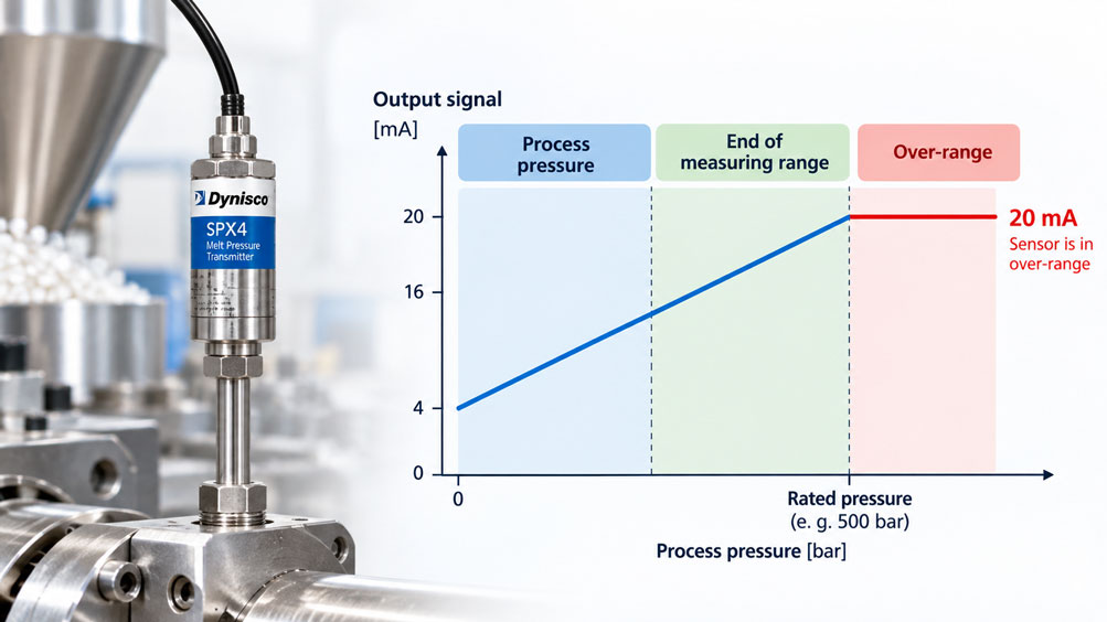
At a plastics extrusion plant, a Dynisco melt pressure transmitter monitors the melt pressure upstream of a screen changer. The transmitter has a pressure measuring range of 0 … 350 bar and provides an analog output signal of 4 … 20 mA. During normal operation, the machine controller indicates a pressure of approximately 240 bar. Following a change in process conditions, however, the indicated pressure increases and eventually reaches the upper display limit. At the same time, the transmitter output signal reaches 20 mA.
Maintenance personnel are now faced with an important question: Is the melt pressure actually dangerously high, or has the electrical output signal merely reached its specified upper range limit? The PLC could also be incorrectly scaled, causing a correct 20 mA signal to be displayed as an incorrect process pressure. Another possibility is that the transmitter is already operating outside its calibrated measuring range and its output signal no longer increases proportionally.
When a conventional 4–20 mA melt pressure transmitter reaches 20 mA, this initially has a clearly defined meaning: The electrical signal corresponds to the configured upper range value. However, this does not automatically mean that the mechanical overpressure limit of the sensor has been reached or that the permissible pressure loading of the extrusion system has been exceeded.
The situation becomes particularly critical if the pressure rises beyond the configured measuring range. Depending on the transmitter, the current signal may continue to increase, become limited at a defined value or enter a fault current range when certain diagnostic faults are detected. A signal limited to 20 mA then provides no clear indication of how high the actual process pressure may be above the measuring range.
The entire electrical measurement chain must also be considered. The transmitter generates the 4–20 mA signal, a PLC analog input measures the current, and the control software converts it into a physical pressure value. Even a difference in measuring range configuration can cause the sensor and machine display to represent different pressure values.
This technical article explains how to correctly evaluate a Dynisco melt pressure transmitter reaching 20 mA. It focuses on measuring range, output characteristics, overrange, mechanical overpressure resistance, fault signals according to NAMUR NE 43 and correct PLC scaling. A calculation example demonstrates the relationship between current signal and melt pressure, together with the effects of incorrectly configured indication. Measuring bores, temperature, zero adjustment, shunt calibration, signal diagnostics and suitable Dynisco components from the ICS product range are also discussed.
Table of Contents
- Define the Melt Pressure Measurement Task and Permissible Process Pressure
- Understand the Measuring Principle of a Melt Pressure Transmitter
- Correctly Interpret the 4–20 mA Output Characteristic
- Understand What an Output Signal of 20 mA Actually Means
- Distinguish Measuring Range Exceedance from Mechanical Overpressure
- Correctly Evaluate NAMUR NE 43, Signal Limiting and Fault Currents
- Check Scaling in the PLC, Process Indicator and Control System
- Calculation Example: 4–20 mA with a Measuring Range of 0 … 350 bar
- Distinguish Sensor Range, Measuring Span and HART Configuration
- Evaluate Actual Process Pressure Independently of the Current Signal
- Investigate the Complete Signal Path from Sensor to Machine Display
- Check Supply Voltage, Loop Burden and Two-Wire Technology
- Correctly Use the Internal 80% Shunt Calibration
- Check Zero and Span Under Suitable Process Conditions
- Consider Temperature Changes, Capillary Tubes and Thermal Zero Drift
- Inspect the Mounting Bore, Diaphragm and Mechanical Installation
- Identify Process-Related Causes of Increasing Melt Pressure
- Evaluate Pressure Peaks, Response Time and Signal Filtering
- Correctly Design Pressure Limits, Alarms and Safety Functions
- Perform a Systematic Diagnostic and Testing Procedure
- Diagnose Typical Fault Patterns Involving 20 mA Signals
- Suitable Dynisco Melt Pressure Transmitters and Indicators from ICS Schneider
- Conclusion: 20 mA Is a Signal Value, Not a Complete Pressure Diagnosis
- Frequently Asked Questions About 20 mA, Overrange and Melt Pressure Measurement
1. Define the Melt Pressure Measurement Task and Permissible Process Pressure
Melt pressure transmitters are used in plastics processing to measure the pressure of hot polymer melts or other suitable process media.
Typical measuring points are located on extruders, upstream or downstream of screen changers, upstream of melt pumps or in the area of extrusion dies.
Pressure measurement can serve different purposes.
One measuring point may be used exclusively for process indication and monitoring stable production conditions.
Another measuring point may be used to control a melt pump or monitor a defined pressure limit.
In appropriately designed installations, the pressure value may also form part of a safety-related control function.
These different purposes must be distinguished when selecting and configuring the transmitter.
Determining the actual permissible process pressure is particularly important.
A transmitter with a measuring range up to 350 bar does not automatically mean that the installation may be operated at pressures up to 350 bar.
The permissible pressure may be limited by the extrusion barrel, a die, a filter or another mechanical component.
Short-term pressure peaks may also be relevant.
The limits must therefore be derived from the design of the actual installation.
For a reliable measurement task, at least the normal operating pressure, maximum permissible process pressure, possible pressure impulses, melt temperature and required measurement dynamics must be known.
Only then can the technically suitable sensor measuring range and alarm thresholds be determined.
2. Understand the Measuring Principle of a Melt Pressure Transmitter
A melt pressure transmitter converts the pressure of a process medium into an electrical output signal.
In many conventional Dynisco melt pressure transducers, process pressure is detected by a metallic measuring diaphragm.
Depending on the sensor design, the pressure is transmitted to a sensitive measuring element through a suitable transmission system, such as a fluid-filled capillary tube.
The mechanical deformation is frequently detected using a strain gauge arrangement.
A typical design uses a Wheatstone bridge with four active resistive elements.
In a melt pressure transmitter with an integrated amplifier, the corresponding sensor signal is then processed electronically.
The electronics provide a standardised current signal of 4 … 20 mA, for example.
This allows the transmitter to be connected directly to suitable PLC analog inputs, process indicators or control systems.
The actual electrical configuration depends on the specific Dynisco model.
A conventional unamplified melt pressure transducer may, for example, provide an output signal in mV/V.
Such a sensor requires suitable external signal conditioning.
An amplified 4–20 mA transmitter, on the other hand, incorporates the electronics required to generate the industrial current signal.
This distinction is important for troubleshooting.
If an unsuitable input type is used or the wrong sensor type is configured, the indicated pressure may differ considerably from the actual process pressure.
3. Correctly Interpret the 4–20 mA Output Characteristic
The 4 … 20 mA current signal is widely used in industrial process measurement technology.
For a correspondingly configured linear pressure transmitter, a current of 4 mA represents the lower range value.
A current of 20 mA represents the upper range value.
Between these two points, the characteristic is proportional when linear pressure scaling is used.
The signal span is:
ΔI = 20 mA − 4 mA = 16 mA
For a transmitter with a measuring range of 0 … 350 bar, for example:
4 mA = 0 bar
12 mA = 175 bar
20 mA = 350 bar
One major advantage of the 4–20 mA signal is that the normal measuring range does not begin at 0 mA.
This makes it possible to distinguish certain electrical fault conditions, such as a completely interrupted current loop, from a valid lower range value.
However, the absence of current does not automatically identify one specific electrical fault.
It can also be caused by a missing supply voltage or another interruption in the signal path.
Furthermore, behaviour outside the nominal 4–20 mA span depends on the transmitter and its configuration.
The normal linear relationship between current and pressure applies only within the specified conditions.
Particularly when the current signal reaches the upper measuring range limit, the normal characteristic must therefore be distinguished from possible conditions outside the range.
4. Understand What an Output Signal of 20 mA Actually Means
For a conventional linearly configured 4–20 mA pressure transmitter, a signal of 20 mA corresponds to the configured upper range value.
With a measuring range of 0 … 350 bar, this initially means that the output signal has reached the value assigned to 350 bar.
However, this does not automatically prove that the actual process pressure is exactly 350 bar.
Such an interpretation assumes that the transmitter is measuring correctly, is configured properly and is not operating in a special condition.
For example, certain intelligent transmitters can limit their output signal at the upper range boundary.
If the actual pressure continues to increase, the electrical signal may nevertheless remain constant.
A PLC can also limit a higher input value to the upper display range.
The display may then continuously indicate 350 bar even though the actual transmitter current or process conditions are changing.
Incorrect configuration is another possibility.
If the machine controller expects a measuring range of 0 … 500 bar while the connected sensor is configured for 0 … 350 bar, the same current signal can be interpreted incorrectly.
It is therefore particularly important to distinguish between the electrical current value, transmitter configuration and displayed pressure value.
A signal of 20 mA alone does not provide conclusive evidence of mechanical overloading or a process fault.
5. Distinguish Measuring Range Exceedance from Mechanical Overpressure
Different pressure limits must be considered separately for melt pressure transmitters.
The first limit is the configured upper range value.
This describes the pressure value assigned to the upper output signal of 20 mA.
The second limit may be the physical nominal pressure range of the sensor.
With configurable transmitters, the configured output range may be smaller than the original physical sensor measuring range.
The third limit is the mechanical overpressure resistance of the sensor.
This describes a permissible short-term pressure load under the specified conditions.
Such an overpressure limit does not automatically represent an extended calibrated measuring range.
For the Dynisco PT46X4 series, for example, an overpressure limit of up to twice the full-scale measuring range or a maximum of 35,000 psi is specified, whichever is lower.
This specification describes a mechanical loading limit of the corresponding sensor configuration.
It does not mean that pressure measurements up to this value retain the normal specified accuracy.
The permissible process limits of the extrusion system also remain applicable independently.
A sensor may therefore withstand a certain pressure exceedance mechanically even though its output signal has already left the calibrated range.
Conversely, the permissible pressure of the installation may be considerably lower than the upper range value of the sensor.
Reliable diagnosis therefore requires separate knowledge of the configured output range, physical sensor measuring range, mechanical overpressure limit and maximum permissible process pressure.
6. Correctly Evaluate NAMUR NE 43, Signal Limiting and Fault Currents
Suitable industrial 4–20 mA transmitters may provide additional signal ranges for overrange and fault diagnostics.
NAMUR Recommendation NE 43 describes a standardised distinction between measurement information and fault signals.
Under the corresponding concept, normal measurement information is contained within a defined current range.
Very low or high current levels are used, for example, to identify diagnosed failures.
For the Dynisco MDT435F and MDT467F models, fault signal levels of 3.6 mA or less and 21 mA or more are documented.
Dynisco also describes corresponding fault current levels for suitable SPX4222/SPX4622 configurations.
However, the actual output response depends on the particular model and its configuration.
| Current Signal | Typical Meaning | Important Limitation |
|---|---|---|
| 0 mA or no measurable loop current | Possible cable break, missing supply voltage or open current loop | The exact cause cannot be determined without further investigation |
| ≤ 3.6 mA | Lower fault current range according to NAMUR NE 43 | Interpret only according to the actual transmitter and diagnostic configuration |
| 4.0 mA | Lower range value | Normally 0 bar for a measuring range beginning at 0 bar |
| 12.0 mA | 50 % of the configured measuring span | Applies to linear 4–20 mA scaling |
| 20.0 mA | Configured upper range value | Does not automatically indicate mechanical overloading |
| Above 20 mA up to, for example, 20.5 mA | Possible upper measurement or saturation range in suitably designed instruments | Whether a valid overrange measurement is transmitted depends on the model |
| ≥ 21 mA | Upper fault current range according to NAMUR NE 43 | Must be treated as a diagnosed failure in instruments with the corresponding fault current configuration |
The table illustrates the general classification. It does not replace the actual output specifications of the transmitter used.
In particular, a current slightly above 20 mA must not automatically be interpreted as an accurate measurement of a correspondingly higher pressure.
The range between normal measurement information and a clearly defined fault current threshold must also be handled according to the instrument specifications.
Distinguishing between a limited upper output signal and a diagnosed fault is particularly important for PLC processing.
A current value defined as a fault signal must not simply be converted into an apparently higher pressure reading and used as a normal process measurement.
7. Check Scaling in the PLC, Process Indicator and Control System
Most industrial PLC systems initially process the 4–20 mA signal as an electrical input value.
This value is subsequently converted into a physical quantity.
For a pressure transmitter, this is frequently pressure expressed in bar.
Correct scaling requires the lower and upper current values and their corresponding physical measuring range limits.
For a linear characteristic, the general relationship is:
p = pLRV + (I − 4 mA) / 16 mA · (pURV − pLRV)
Here, pLRV represents the configured lower range value and pURV the configured upper range value.
For a measuring range of 0 … 350 bar, the equation simplifies to:
p = (I − 4 mA) / 16 mA · 350 bar
The PLC must also be configured correctly for the electrical input type used.
An analog input configured for 0 … 20 mA can produce incorrect measurements when evaluating a 4–20 mA sensor if the subsequent conversion does not account for this difference.
Different internal raw-value ranges of PLC analog modules must also be considered.
Such modules may initially convert the electrical current into digital counts.
The subsequent scaling must correspond to the actual module configuration.
It should also be checked whether the software clips values exceeding the measuring range.
A display with a fixed maximum value may otherwise conceal a further pressure increase or a diagnostically abnormal current signal.
For a complete assessment, the actual loop current, raw analog input value and scaled pressure value must therefore be examined separately.
8. Calculation Example: 4–20 mA with a Measuring Range of 0 … 350 bar
A Dynisco melt pressure transmitter has a configured pressure range of 0 … 350 bar.
The analog output signal is 4 … 20 mA.
The associated PLC is intended to display the melt pressure in bar.
For an ideal linear characteristic:
p = (I − 4 mA) / 16 mA · 350 bar
With a current signal of 16 mA:
p = (16 mA − 4 mA) / 16 mA · 350 bar
p = 262.5 bar
At 18.4 mA:
p = (18.4 mA − 4 mA) / 16 mA · 350 bar
p = 315.0 bar
The following table shows the relationship for several current values.
| Current Signal | Percentage of Measuring Span | Pressure with Correct Scaling | Indication with Incorrect 0 … 500 bar Scaling |
|---|---|---|---|
| 4.0 mA | 0 % | 0.0 bar | 0.0 bar |
| 8.0 mA | 25 % | 87.5 bar | 125.0 bar |
| 12.0 mA | 50 % | 175.0 bar | 250.0 bar |
| 16.0 mA | 75 % | 262.5 bar | 375.0 bar |
| 18.4 mA | 90 % | 315.0 bar | 450.0 bar |
| 20.0 mA | 100 % | 350.0 bar | 500.0 bar |
The table demonstrates that a correct current signal can produce significantly different pressure indications if PLC scaling is configured incorrectly.
An error at the upper range limit is particularly critical.
With an actual input current of 20 mA, a correctly configured PLC indicates 350 bar.
A PLC incorrectly scaled to 0 … 500 bar would instead indicate 500 bar.
Both indications result from the same current signal.
Another important consideration is the pressure alarm threshold.
Assume that the maximum permissible process pressure of the machine is 300 bar.
The corresponding ideal current value is:
I = 4 mA + 16 mA · (300 bar / 350 bar)
I ≈ 17.71 mA
The safety-related or process-related limit may therefore be reached well below 20 mA.
In this example, waiting until the signal reaches 20 mA would not be an appropriate method of detecting the first occurrence of excessive pressure.
The actual warning and shutdown thresholds must be derived from the permissible mechanical loading of the installation and its protection concept.
Another limitation concerns measured currents above 20 mA.
If a current of 20.4 mA is measured, for example, a reliable process pressure cannot automatically be calculated from this value.
Extrapolation of the mathematical characteristic would only be physically meaningful if the specific instrument specifies valid pressure transmission within this output range.
This requirement may not be fulfilled if signal limiting or an emerging fault condition is present.
The calculations describe an ideal linear 4–20 mA characteristic. Sensor measurement errors, temperature drift and other influences are not included.
9. Distinguish Sensor Range, Measuring Span and HART Configuration
With certain intelligent melt pressure transmitters, the assignment of the pressure range to the 4–20 mA output can be modified.
This function is frequently described as range adjustment, rangeability or turndown.
For example, a transmitter may contain a pressure sensor with a particular physical measuring range while its electrical output span is configured for a smaller usable range.
The available options depend on the specific model.
Dynisco provides corresponding functions for certain intelligent SPX pressure transmitters, among others.
Suitable models can be configured via HART.
For correct interpretation, the original sensor range and the currently configured analog range limits must be considered separately.
Changing the output range does not automatically change the mechanical pressure resistance of the sensor.
The physical accuracy and specified operating limits must also be evaluated for the selected configuration.
Consistent configuration with the PLC is particularly important.
If the analog output range is changed in the transmitter while the PLC continues to calculate using the previous measuring range, systematic indication errors occur.
With intelligent transmitters, internal digital process variables and the analog current output can also be examined separately.
This can assist troubleshooting if the internal pressure variable continues to increase while the analog output has already reached a limit.
The actual availability of such diagnostic functions depends on the selected model and communication configuration.
Changes to the measuring range, zero or span must be documented and, where necessary, verified through suitable testing of the measurement chain.
10. Evaluate Actual Process Pressure Independently of the Current Signal
When a melt pressure transmitter continuously outputs 20 mA, one important question is whether the corresponding process pressure is actually present.
Direct electrical measurement of the current signal alone cannot conclusively answer this question.
It initially only confirms the current flowing within the measurement loop.
Suitable independent pressure information is required to assess the actual pressure.
This may be provided by a second appropriately designed pressure measuring point, for example.
Suitable testing of the transmitter against a traceable pressure reference may also be necessary to evaluate its condition.
Performing such a test is particularly challenging with high-temperature melt pressure measurements.
The sensor is connected to a process that may be extremely hot and under high pressure.
A conventional hydraulic hand test pump is not automatically suitable for direct testing on an installed hot extruder.
Testing must follow the permissible procedures and manufacturer specifications.
Another possible diagnostic method with suitable intelligent transmitters is to compare the internally measured process variable with the analog output current.
Such digital diagnostics can help identify whether the cause lies in analog output limiting or scaling.
However, the internal process variable is derived from the same sensor.
It is therefore not a fully independent physical reference for the actual melt pressure.
In particular, diaphragm damage or blocked pressure transmission paths may also cause the internal pressure variable to be incorrect.
A reliable process assessment must therefore consider the complete mechanical and metrological situation.
11. Investigate the Complete Signal Path from Sensor to Machine Display
The melt pressure indication frequently results from several consecutive processing steps.
First, the sensor diaphragm detects the pressure.
The measuring system generates an electrical signal from this pressure.
The integrated transmitter converts the signal into a corresponding output current.
A PLC or separate process indicator measures the current and calculates the pressure to be displayed.
For troubleshooting, it is useful to examine these stages separately.
A fault in the mechanical measuring system may already occur before electrical signal processing takes place.
A defect in the electronics may cause the output signal to no longer correspond to the internally measured pressure.
An electrical fault in the current loop may also produce an implausible current value.
Finally, incorrect PLC scaling can convert a correctly transmitted current into an incorrect pressure value.
Suitable diagnostics should therefore compare at least the actual current, the raw analog input value and the scaled display value.
Additional instrument information may be considered if HART communication is available.
It is particularly important to establish whether the display is limited to the upper range value.
If the PLC continuously displays a fixed maximum value, this may result from display limiting rather than a constant actual process pressure.
The individual processing stages must therefore be checked against their respective configurations.
12. Check Supply Voltage, Loop Burden and Two-Wire Technology
Many Dynisco melt pressure transmitters with a 4–20 mA output use two-wire technology.
In this configuration, electrical power and signal transmission share the same two conductors.
The transmitter regulates the current flowing through the corresponding current loop.
Sufficient supply voltage must be available for correct transmission of the output signal.
The transmitter must also receive the voltage necessary to operate its own electronics.
The remaining voltage is dropped across components such as the analog input, cable resistance and other elements in the loop.
For a simple current loop with a resistive total burden:
Uburden = I · Rburden
At a loop current of 20 mA and a resistance of 500 Ω:
Uburden = 0.020 A · 500 Ω = 10 V
This voltage is no longer available to the transmitter.
If the supply voltage is insufficient, correct output operation may be impaired.
Particularly with long cables and additional signal isolators or display units, the complete voltage budget must be considered.
The actual permissible burden depends on the model.
For the Dynisco MDT435F/MDT467F series, for example, 500 Ω at 24 V DC and 1,200 Ω at 36 V DC are specified.
These specifications must not automatically be applied to all Dynisco transmitters.
Intrinsically safe ATEX applications involve additional requirements concerning power supply, isolation barriers and permissible electrical interconnection.
Electrical current measurement must also be performed correctly.
For a suitable two-wire current loop, a current measuring instrument is connected in series according to the specified measurement procedure.
An unsuitable test instrument connection can alter the current loop or cause a dangerous malfunction.
The actual testing conditions must therefore be derived from the manufacturer documentation and the installation’s safety concept.
13. Correctly Use the Internal 80% Shunt Calibration
Many Dynisco melt pressure sensors have an internal electrical calibration function.
This is commonly referred to as R-Cal or shunt calibration.
The method enables a defined electrical test signal to be generated without applying the corresponding physical process pressure.
In suitable Dynisco sensors, the R-Cal signal represents 80 % of the full-scale measuring range.
For a linear 4–20 mA signal:
IR-Cal = 4 mA + 0.80 · 16 mA
IR-Cal = 16.8 mA
With a configured pressure range of 0 … 350 bar, this current corresponds mathematically to:
pR-Cal = 0.80 · 350 bar = 280 bar
During a corresponding specified R-Cal test, a correctly scaled indicator should display the intended simulated pressure value.
The actual process pressure does not need to be 280 bar.
Shunt calibration is therefore particularly useful for checking the relationship between the electrical sensor output and the process indicator.
For example, it can reveal incorrect PLC scaling.
Faulty electrical signal transmission may also be investigated under appropriate conditions.
However, correct interpretation is essential.
R-Cal generates a defined electrical test condition and does not provide complete evidence that the process diaphragm and pressure transmission system are functioning mechanically correctly.
A blocked pressure channel or damaged measuring system may still produce a plausible electrical R-Cal signal.
The shunt function therefore does not replace complete pressure calibration using a suitable pressure reference.
Activation must follow the applicable Dynisco instructions. If the sensor is connected to a control or safety system, the possible effects of the simulated signal must be considered in advance.
14. Check Zero and Span Under Suitable Process Conditions
A melt pressure transmitter may exhibit a zero-point shift caused by temperature changes and other influences.
Many corresponding Dynisco configurations therefore provide a zero adjustment function.
Certain models allow local adjustment at the electronics housing.
Other configurations also permit remote zero adjustment.
Correct adjustment requires the pressure conditions specified by the manufacturer to be present.
For suitable melt pressure sensors, Dynisco recommends adjusting the zero at operating temperature without applied pressure.
This allows temperature-related zero-point changes to be taken into account.
Zero adjustment while process pressure is present would, however, be problematic.
If actual pressure acts on the diaphragm and this condition is stored as the zero point, a systematic measurement error results.
This can also change the relationship between pressure and the 20 mA output signal.
Particularly on an operating extrusion line, a zero correction must not be initiated merely because the indicated pressure appears too high.
It must first be reliably established whether the conditions required for zero adjustment are actually fulfilled.
The measuring span must also not be modified without a suitable reference and traceable procedure.
Incorrect adjustment may initially produce plausible process indications even though the actual pressure measurement is no longer correct.
For demanding applications, zero and span adjustments should therefore be documented and verified through suitable testing.
15. Consider Temperature Changes, Capillary Tubes and Thermal Zero Drift
Melt pressure transmitters are frequently used at high process temperatures.
Suitable Dynisco series permit diaphragm temperatures up to 400 °C.
However, this value does not automatically apply to the entire electronics housing.
The electronics normally have their own permissible ambient temperature range.
In many melt pressure sensors, a rigid stem or flexible capillary connection therefore separates the hot measuring diaphragm from the sensitive electronics housing.
Temperature changes can influence the properties of both the mechanical and electrical measuring systems.
In fluid-filled pressure transmission systems, for example, the temperature of the fill medium may affect the zero point.
The sensor electronics also have a specified temperature dependence.
Different temperature conditions can occur particularly during extruder start-up.
A pressure reading taken immediately after start-up may therefore not have been obtained under the same thermal conditions as the subsequent stable production value.
A temperature-related zero-point deviation can affect the entire output characteristic.
Additional temperature compensation is therefore used in certain Dynisco SPX-T configurations.
For example, the SPX-T 3242 combines corresponding temperature compensation with Dynisco DynaLarity technology.
These functions can reduce temperature-related measurement deviations.
However, they do not replace checking correct installation, the permissible temperature range and actual process conditions.
A signal that continuously remains at the upper range value under high-temperature conditions must still be investigated for possible process or sensor faults.
16. Inspect the Mounting Bore, Diaphragm and Mechanical Installation
The mechanical installation conditions significantly influence the functionality of a melt pressure transmitter.
Many Dynisco sensors have a 1/2″-20 UNF process connection.
For these configurations, the mounting bore must comply with the specified dimensions and sealing surfaces.
Correct centring, bore depth and suitable sealing geometry are particularly important.
An incorrectly machined mounting bore can place mechanical stress on the sensor.
Unsuitable tightening torque may also deform the measuring element and cause a zero-point shift.
Dynisco explicitly states that a significant zero shift during installation may indicate an incorrect mounting bore or excessive tightening torque.
Another problem involves deposits of solidified polymer melt.
If material accumulates in front of the measuring diaphragm or partially blocks the pressure transmission path, the pressure measurement may become delayed or distorted.
An electrically plausible output signal therefore does not automatically mean that the process pressure is correctly transmitted to the diaphragm.
The diaphragm itself must also remain undamaged.
Mechanical damage may result from unsuitable cleaning tools, improper installation or impermissible pressure loading.
Inspection of the diaphragm and mounting bore must only be performed according to an appropriate safe procedure.
Particularly in hot extrusion systems, pressurised polymer melt can cause severe burns and other injuries.
The sensor must therefore not be removed or loosened uncontrollably while process pressure is present.
The specified Dynisco tools and manufacturer instructions are decisive for cleaning.
17. Identify Process-Related Causes of Increasing Melt Pressure
If the electrical current of a melt pressure transmitter rises to the upper range value, this may indeed be caused by an actual increase in process pressure.
In extrusion processes in particular, melt pressure depends on several process variables.
These include material properties, melt temperature, screw speed, throughput and flow resistance within the process.
An increasing pressure upstream of a screen changer may, for example, indicate increasing contamination of the filter material.
Changes in material viscosity can also influence melt pressure.
With many polymer melts, a decrease in melt temperature may cause an increase in viscosity.
Under otherwise comparable conditions, the required pressure may therefore increase.
Changes to the die or nozzle may also be relevant.
A restricted flow cross-section can cause a greater pressure drop.
During start-up, partially unmelted material or unfavourable temperature distributions may also occur.
The actual relationships depend on the polymer, the equipment design and process conditions.
For systematic root cause analysis, it can be useful to evaluate melt pressure together with other process variables.
These include melt temperature, pressure upstream and downstream of a filter, screw speed and, where applicable, drive current.
In particular, the difference between two suitable pressure measuring points can provide information about changing flow resistance under comparable operating conditions.
Increasing pressure must therefore not be prematurely interpreted as a sensor fault.
Conversely, it must also be determined whether a continuously high indicated pressure is actually caused by the process or results from a faulty measurement chain.
18. Evaluate Pressure Peaks, Response Time and Signal Filtering
The melt pressure in an extruder is not always constant.
Depending on the process, pressure fluctuations, pulsations and short-term peaks may occur.
These can result from screw movement, pumps, switching operations or changes in flow resistance, for example.
A pressure transmitter can only detect such variations within its specific dynamic capabilities.
Actual response time depends, among other factors, on the sensing element, pressure transmission system and signal conditioning.
Additional electronic damping may also be provided.
With intelligent transmitters, this damping may be configurable.
Greater damping can reduce short-term fluctuations in the displayed value.
However, it may also prevent rapid pressure peaks from appearing in the output signal with their original magnitude or timing.
The same applies to filtering functions in PLCs or control systems.
A stable indicated 20 mA signal may therefore represent a limited or appropriately filtered output signal.
The actual process dynamics may differ.
Particularly with pressure-dependent shutdown functions, the timing requirements and complete signal path must be considered.
The sampling rate of the analog input, PLC cycle time and any enabled filters may influence the response.
High measurement accuracy under steady-state conditions does not automatically mean that short pressure events can be detected sufficiently quickly.
For demanding applications, the required temporal resolution of the complete measurement chain must therefore be defined.
19. Correctly Design Pressure Limits, Alarms and Safety Functions
Continuously high melt pressure may indicate a critical process condition in extrusion systems.
High pressure can increase the mechanical loading of equipment, particularly upstream of filters, melt pumps or dies.
For safe system design, permissible process limits must be defined independently of the sensor measuring range.
A transmitter with a measuring range of 0 … 350 bar does not mean that an alarm should only be triggered at 350 bar.
If an installation permits a maximum pressure of 300 bar, for example, the intended warning and shutdown functions must be designed accordingly.
Handling measuring range exceedances and electrical faults is particularly important.
A signal limited to 20 mA must not be used as evidence that the actual pressure is no longer increasing.
A diagnosed fault signal according to NAMUR NE 43 must also be handled according to the intended installation function.
For suitably designed and configured transmitters, a fault current of at least 21 mA, for example, must not simply be interpreted as a normal pressure value above the measuring range.
In safety-related applications, the corresponding evaluation must clearly define which conditions are considered hazardous or invalid.
It must also be considered that certain mechanical sensor faults do not automatically generate an electrical fault signal.
A blocked pressure channel, for example, may cause the measuring system to detect an incorrect pressure even though the electrical current loop appears plausible.
Consequently, the complete safety function must be considered even when a suitably SIL2-assessed melt pressure transmitter is used.
This includes the sensor, signal evaluation, logic, necessary diagnostics, final shutdown element and specified periodic tests.
A sensor’s SIL2 capability does not automatically mean that the entire extrusion installation achieves the corresponding safety integrity.
The required safety function must be designed and validated for the specific machine according to the applicable requirements.
20. Perform a Systematic Diagnostic and Testing Procedure
When a melt pressure transmitter reaches 20 mA or remains continuously at its upper range value, the cause should be identified systematically.
The following steps describe a general technical approach for appropriately qualified personnel.
They do not constitute authorisation to work on a hot or pressurised extrusion system. Actual work must follow the manufacturer instructions and the approved safe procedure for the installation.
- Identify the measuring point: Record the transmitter manufacturer, model, complete order number and installation location.
- Determine the output signal: Check whether the instrument is actually a 4–20 mA transmitter or a sensor with another electrical output.
- Document the measuring range: Establish the nominal pressure range and currently configured analog span using the available documentation.
- Check process limits: Record normal operating pressure, maximum permissible installation pressure and intended alarm thresholds.
- Evaluate current operating conditions: Determine whether the indicated pressure suggests a potentially critical process condition.
- Investigate signal status: Establish whether the transmitter is producing a regular upper range value, a limited output or a diagnosed fault current.
- Check electrical current: Measure the actual loop current using a suitable procedure and appropriately approved testing instrument.
- Compare the PLC raw value: Verify that the measured analog input value corresponds to the actual current signal.
- Check scaling: Compare the lower and upper pressure values and electrical input configuration with the transmitter settings.
- Identify limiting functions: Check whether the display, PLC or transmitter limits values at the upper range boundary.
- Check power supply: Evaluate permissible supply voltage and total current loop burden against the manufacturer specifications.
- Evaluate diagnostic information: With suitable HART transmitters, consider internal process values, status information and configuration parameters.
- Compare process measurements: Evaluate the pressure indication against suitable independent measurements and relevant process variables.
- Record temperature conditions: Consider diaphragm temperature, electronics temperature and possible thermal zero-point changes.
- Evaluate mechanical influences: Under appropriately safe installation conditions, investigate the mounting bore, possible material deposits and indications of diaphragm damage.
- Check zero adjustment conditions: Plan zero adjustment only under the specified pressure-free or manufacturer-defined conditions.
- Use the electrical test function: Use an available R-Cal or shunt function according to the manufacturer instructions to check the signal chain.
- Evaluate pressure calibration: If deviations persist, arrange suitable testing with an independent pressure reference or manufacturer inspection.
- Eliminate the fault cause: Correct identified configuration, wiring, sensor or process problems according to an approved procedure.
- Document the results: Record instrument data, measuring ranges, process conditions, electrical values, test results and the approved configuration.
It is particularly important to distinguish between electrical signal testing and physical pressure calibration.
A correct 4–20 mA signal may confirm the electrical measurement chain but does not automatically prove the actual melt pressure.
Likewise, a possible mechanical fault must not be concealed merely by changing PLC scaling or zero adjustment.
Reliable diagnosis requires the different stages of the measurement chain to be investigated separately and subsequently evaluated together.
21. Diagnose Typical Fault Patterns Involving 20 mA Signals
An abnormal output signal may have different causes. It is particularly important to distinguish actual pressure changes from electrical and mechanical measurement faults.
| Observation | Possible Cause | Suitable Check |
|---|---|---|
| Transmitter provides 20 mA when nominal pressure is reached | Regular upper range value | Compare measuring range, process limits and permissible pressure loading |
| PLC indicates 500 bar while the sensor is configured for 0 … 350 bar | Incorrect PLC pressure scaling | Check analog input configuration and configured pressure span |
| Current remains at 20 mA although pressure apparently continues to increase | Possible output limiting or inadequate detection of the actual pressure | Evaluate instrument specifications, internal process variable and independent pressure information |
| Current signal is at least 21 mA | Diagnosed fault condition according to NAMUR NE 43 in appropriately configured instruments | Check instrument status and documented fault current behaviour |
| Output current is 3.6 mA or less | Possible lower fault current according to NAMUR NE 43 | Check transmitter diagnostics and electrical current loop |
| No current signal is present | Interrupted current loop, missing supply voltage or connection fault | Check power supply and electrical connections using a suitable testing procedure |
| Indication is correct at zero but not at higher pressures | Incorrect span, scaling or sensor characteristic | Compare several defined signal or pressure points |
| Indication changes significantly after installing the sensor | Mechanical stress, incorrect mounting bore or excessive tightening torque | Evaluate the installation professionally according to Dynisco specifications |
| Signal responds slowly or hardly at all to pressure changes | Blocked pressure channel, solidified melt or damaged measuring system | Check mechanical pressure transmission and sensor condition |
| Zero point changes after heating | Temperature-related zero drift | Check temperature conditions and permissible zero adjustment procedure |
| R-Cal indicates the expected value, but the process pressure indication remains abnormal | Electrical signal chain appears plausible, but a mechanical sensor fault is still possible | Arrange suitable independent pressure testing or manufacturer diagnostics |
| Signal fluctuates significantly while the extruder operates | Actual pressure pulsation, electrical interference or unsuitable damping | Evaluate process behaviour, signal path and dynamic acquisition separately |
| Indication does not increase further at high pressure | Limiting in the transmitter, PLC function block or indicator | Compare raw current, digital value and display limits |
| Pressure rises significantly after a filter or material change | Changed process conditions or additional flow resistance | Compare melt temperature, throughput, filter condition and other process variables |
The table lists possible causes and suitable diagnostic approaches.
The actual fault cause must be established for the specific measuring system.
It is particularly important to recognise that the output signal does not necessarily indicate a clearly defined electrical fault condition when the actual pressure exceeds its intended limit.
A current signal remaining at the upper range value may still be electrically valid.
For equipment monitoring, it is therefore necessary to know how the specific transmitter responds to an actual exceedance of its intended pressure range.
22. Suitable Dynisco Melt Pressure Transmitters and Indicators from ICS Schneider
22.1 Dynisco PT46X4: 4–20 mA Melt Pressure Transmitters for Extrusion Processes
The Dynisco PT46X4 series comprises industrial melt pressure transmitters with amplified 4–20 mA outputs.
The series is intended for general melt pressure measurement applications in plastics processing.
Available pressure ranges extend from 0 … 500 psi to 0 … 30,000 psi.
The specified accuracy is ±0.5 % of full scale as a combined error of linearity, repeatability and hysteresis.
Features include adjustable zero and span together with internal 80 % shunt calibration.
For suitable configurations, zero adjustment can be performed locally or via a corresponding external contact.
The series includes PT4604, PT4624 and PT4634, among others, as well as corresponding TPT configurations with additional temperature measurement.
The standard wetted components are made of DyMax-coated stainless steel.
A maximum diaphragm temperature of 400 °C is specified for corresponding versions.
The PT46X4 series is suitable for direct connection to appropriate PLC and control systems.
A safety-related assessment for SIL2 or Performance Level “c” is also documented for appropriately specified applications.
However, permissible use in a particular safety function must be evaluated based on the complete installation architecture.
For diagnosing a continuously high current signal, correct pressure range assignment, diaphragm condition and the electrical signal chain are particularly important.
22.2 Dynisco MDT435F / MDT467F: Melt Pressure Transmitters with NAMUR Fault Signals
The Dynisco MDT435F / MDT467F series comprises compact two-wire melt pressure transmitters with a 4 … 20 mA output signal.
The series is particularly intended for industrial environments with high levels of electrical interference and limited installation space.
Available pressure measuring ranges extend from 0 … 35 bar to 0 … 2,000 bar.
Depending on the pressure range, the MDT435F model has a specified accuracy of ±0.5 % or ±1.0 % of full scale.
An accuracy of ±1.0 % of full scale is specified for the MDT467F model.
One important feature is the Auto-Zero function.
Under suitable conditions, zero adjustment can be initiated locally at the instrument or through a corresponding external connection.
The series also provides integrated electrical span calibration with a signal corresponding to 80 % of the full-scale measuring range.
The documented fault current behaviour is particularly important for diagnostics.
The transmitters support fault current signals according to NAMUR NE 43, with levels of 3.6 mA or less and 21 mA or more.
With appropriate evaluation, this allows certain diagnosed failures to be distinguished from normal process values.
However, this function does not provide complete monitoring of every possible mechanical fault.
Both the current loop and actual pressure transmission must therefore be considered when monitoring extrusion processes.
22.3 Dynisco SPX4222 / SPX4622: Intelligent Pressure Transmitters with Optional HART
The Dynisco SPX4222 / SPX4622 series consists of intelligent two-wire pressure transmitters with an analog 4–20 mA output signal.
The instruments were developed for industrial melt pressure measurement and applications in potentially explosive atmospheres, among other uses.
Corresponding ATEX configurations are available depending on the specification.
A HART interface is also available for suitable versions.
The available measuring span can be adjusted within the specified limits.
For the SPX4222 series, accuracy of up to ±0.25 % of full scale is specified depending on the pressure range.
The SPX4622 model has a specified accuracy of ±0.50 % of full scale.
The series provides different mechanical configurations and optional temperature sensing elements.
The possible digital communication functionality is particularly useful for diagnostics.
With appropriately equipped transmitters, configuration parameters and additional diagnostic information can be accessed via HART.
For example, this makes it possible to check which pressure values are assigned to the analog outputs of 4 mA and 20 mA.
Possible output limiting or a diagnosed fault condition must nevertheless be evaluated based on the actual instrument configuration.
The HART function is particularly useful for distinguishing between the analog current signal and the internal process variable.
22.4 Dynisco SPX-T 3242: Temperature-Compensated Melt Pressure Measurement
The Dynisco SPX-T 3242 is an intelligent melt pressure transmitter with temperature-compensated measurement processing.
It features an analog 4–20 mA pressure output and a HART interface.
Pressure measuring ranges extend from 500 psi to 10,000 psi.
Depending on the range, the specified accuracy is up to ±0.25 % of full scale.
One special feature is the integrated temperature compensation.
This reduces temperature-related changes in the sensor signal and supports stable melt pressure measurement under varying process conditions.
The series also uses Dynisco DynaLarity technology to reduce certain temperature- and process-related deviations in the characteristic curve.
The model is intended for corresponding applications involving high melt temperatures.
Depending on the version, additional temperature measurement options are available.
The additional compensation can offer advantages particularly in extrusion processes with varying temperature conditions.
However, correct configuration of the electrical output and connected PLC remains essential.
Temperature-compensated measurement does not automatically eliminate every possible cause of a continuously high 20 mA signal.
22.5 Dynisco TDT432F / TDT463F: Combined Melt Pressure and Temperature Measurement
The Dynisco TDT432F / TDT463F series combines melt pressure measurement with additional temperature sensing.
The instruments feature an integrated type J thermocouple for measuring melt temperature.
Pressure is transmitted through an analog 4–20 mA two-wire signal.
Available pressure ranges extend from 0 … 35 bar to 0 … 2,000 bar.
Depending on the model, the specified pressure measurement accuracy is ±0.5 % or ±1.0 % of full scale.
The maximum diaphragm temperature is 400 °C for appropriately designed versions.
The instruments also include an Auto-Zero function and an internal electrical calibration feature.
Fault current behaviour according to NAMUR NE 43 is documented for suitable configurations.
The additional temperature measurement can be particularly helpful when analysing changes in melt pressure.
If pressure rises at an approximately constant throughput, evaluating melt temperature may provide information about changing material properties or process conditions.
The series therefore combines electrical pressure measurement with additional information for process-related root cause analysis.
22.6 Dynisco 1490: Process Indicator for 4–20 mA Signals
The Dynisco 1490 is a universal process indicator in a 1/8 DIN format.
It supports different industrial input signals.
These include 4 … 20 mA, 0 … 20 mA and various voltage and sensor signals.
The instrument features a five-digit LED display with programmable scaling.
Up to two alarm functions can be provided.
Depending on the configuration, an analog output, 24 V transmitter supply and RS-485 communication via Modbus are also available.
Correct current signal configuration is essential when evaluating a Dynisco melt pressure transmitter.
The displayed physical pressure value must correspond to the actual measuring range of the connected transmitter.
The 1490 may therefore be useful for test benches and installations where pressure values need to be displayed and monitored directly.
Particularly when the upper display limit is reached continuously, correct scaling and appropriate signal evaluation must also be checked.
The display alone does not replace verification of the actual process pressure.
22.7 Selecting the Appropriate Measurement Solution for Extrusion Systems
ICS Schneider offers various Dynisco melt pressure sensors, melt pressure transmitters and process indicators for extrusion and plastics processing applications.
Selection must be based on the actual measurement task.
Normal operating pressure, maximum permissible process pressure, required measuring range and possible dynamic pressure peaks are particularly important.
Melt temperature, installation conditions, mounting bore and required electrical interfaces must also be considered.
A suitable 4–20 mA transmitter may be sufficient for straightforward analog pressure measurement.
Where enhanced diagnostics and configuration functions are required, an intelligent version with HART may be useful.
Under varying temperature conditions, an appropriately temperature-compensated configuration may offer advantages.
If safety-related pressure monitoring is intended, the complete safety function, including sensor, evaluation and shutdown element, must be assessed.
Further information and technical support are available under Dynisco Products and Melt Pressure Transmitters.
23. Conclusion: 20 mA Is a Signal Value, Not a Complete Pressure Diagnosis
A melt pressure transmitter reaching 20 mA must be interpreted carefully.
With a conventional linear 4–20 mA output, this current corresponds to the configured upper range value.
However, this does not automatically mean that the actual process pressure is exactly equal to this value or that the mechanical overpressure limit of the sensor has been reached.
It is particularly important to distinguish between the configured electrical measuring range, the physical pressure resistance of the sensor and the permissible process pressure of the installation.
These limits may differ considerably.
Incorrect PLC scaling can also cause substantial measurement errors.
For example, a transmitter with a span of 0 … 350 bar may correctly output its upper range value at 20 mA, while an incorrectly configured PLC calculates a pressure of 500 bar from the same signal.
The electrical output current, raw analog value and scaled pressure indication must therefore be checked separately.
With suitable intelligent transmitters, HART diagnostic information can provide additional assistance when evaluating configuration and signal behaviour.
Behaviour outside the measuring range is also model-dependent.
A transmitter may limit its signal or output appropriately specified fault current levels.
In particular, fault currents according to NAMUR NE 43 must not be interpreted as normal pressure readings.
Mechanical and thermal influences must also be considered during diagnosis.
An incorrect mounting bore, solidified melt, a damaged diaphragm or unsuitable zero adjustment can alter the measurement result.
Internal 80 % shunt calibration is useful for checking the electrical signal chain but does not replace complete mechanical pressure calibration.
Finally, actual process conditions must also be evaluated.
Increasing pressure may result from rising filter resistance, changing melt temperature or other process conditions, for example.
In a critical application, a potentially incorrect measurement must not be concealed merely by adjusting the PLC indication.
Identify the measuring point → Check the sensor measuring range → Measure the 4–20 mA signal → Compare PLC scaling → Distinguish signal limiting and NAMUR fault currents → Evaluate actual process conditions → Obtain independent pressure information → Check the power supply and signal path → Consider temperature and zero point → Evaluate the mounting bore and diaphragm → Perform the electrical test function and, where necessary, pressure calibration → Document the results
The most important practical principle is therefore: 20 mA initially represents the electrical upper range value of a correspondingly configured transmitter. Whether a dangerous process pressure exceedance, incorrect scaling or a sensor problem is present can only be established by evaluating the measuring range, actual pressure loading, transmitter condition and signal processing together.
24. Frequently Asked Questions About 20 mA, Overrange and Melt Pressure Measurement
24.1 What Does 20 mA Mean on a Melt Pressure Transmitter?
On a conventional linearly configured 4–20 mA melt pressure transmitter, 20 mA corresponds to the configured upper range value. With a pressure range of 0 … 350 bar, for example, the signal represents 350 bar. This does not automatically prove mechanical overloading.
24.2 Does 20 mA Automatically Mean That the Process Pressure Is Too High?
No. This depends on the actual permissible process pressure and the transmitter configuration. The machine may reach a critical pressure limit before the upper range value is reached. Likewise, the sensor may be designed for a wider pressure range than the normal operating range.
24.3 What Happens If Pressure Increases Beyond the Upper Range Value?
Behaviour depends on the specific transmitter configuration. The output current may continue to increase within a specified overrange region or may be limited at a particular value. A diagnosed fault may also cause a corresponding fault current. The actual pressure cannot be determined unambiguously from a limited signal.
24.4 What Is the Difference Between Measuring Range and Overpressure Resistance?
The measuring range describes the pressure range over which the specified measurement characteristic and accuracy apply. Overpressure resistance, on the other hand, describes a mechanically permissible pressure load under specified conditions. It does not automatically represent an additional calibrated measuring range.
24.5 Why Does the PLC Display an Incorrect Pressure Value at 20 mA?
One common cause is incorrect scaling. If the transmitter is configured for 0 … 350 bar while the PLC calculates using 0 … 500 bar, the same current signal produces different pressure values. Incorrect analog input configuration can also cause corresponding errors.
24.6 How Do I Convert a 4–20 mA Signal into Bar?
For a linear characteristic: p = pLRV + (I − 4 mA) / 16 mA · (pURV − pLRV). The actual configured lower and upper pressure values must be known.
24.7 How Many Bar Does 16 mA Represent with a Measuring Range of 0 … 350 bar?
16 mA corresponds to 75 % of the electrical measuring span. With a linearly configured pressure range of 0 … 350 bar, the resulting pressure value is 262.5 bar.
24.8 What Does an Output Current of 21 mA Mean?
On a transmitter with appropriately implemented fault current behaviour according to NAMUR NE 43, a current of at least 21 mA may indicate a diagnosed fault condition. Whether this applies depends on the model and its configuration. The value must not automatically be interpreted as a normal pressure reading above the measuring range.
24.9 Can a Melt Pressure Transmitter Output More Than 20 mA?
A current range above 20 mA is possible on appropriately designed models. It may be intended for defined overrange or diagnostic conditions, for example. The exact meaning and permissible output limits are specified in the manufacturer documentation for the particular transmitter.
24.10 Why Does the Display Remain Continuously at the Upper Pressure Value?
Possible causes include an actual high process pressure, limiting of the transmitter output, limiting within the PLC or an incorrectly configured indicator. A sensor problem may also be responsible. Diagnosis requires separate investigation of the actual current and the electrical and physical measurement chain.
24.11 Can a Blocked Pressure Channel Produce a Plausible 4–20 mA Signal?
Yes. If process pressure is not transmitted correctly to the sensor diaphragm because of solidified melt or other deposits, the transmitter may still provide an electrically plausible signal. A current loop test alone will not necessarily detect this fault.
24.12 What Does 80 % Shunt Calibration Mean on Dynisco Sensors?
In appropriately equipped Dynisco sensors, the internal R-Cal function generates a defined electrical signal representing approximately 80 % of full scale. With a linear 4–20 mA output, this corresponds to 16.8 mA. The function allows electrical verification of signal scaling but does not replace complete pressure calibration.
24.13 Can I Zero a Melt Pressure Transmitter While the Extruder Is Running?
Zero adjustment may only be performed under the conditions specified by the manufacturer. For suitable Dynisco melt pressure sensors, adjustment at operating temperature without applied process pressure is recommended. Zero adjustment while actual pressure is present can cause a significant systematic measurement error.
24.14 How Does Temperature Affect Melt Pressure Measurement?
Temperature changes can influence the zero point and sensor sensitivity. The influence of temperature is particularly important in fluid-filled pressure transmission systems. Suitable temperature-compensated configurations can reduce these deviations. The specifications of the particular model are decisive.
24.15 Can Incorrect Tightening Torque Change the Pressure Signal?
Yes. An unsuitable mounting bore or excessive tightening torque can cause mechanical stress in the measuring system and therefore a zero-point shift. Dynisco explicitly identifies such installation faults as possible causes of abnormal zero signals.
24.16 Is a SIL2 Melt Pressure Transmitter Automatically a Safe Overpressure Shutdown System?
No. The safety-related assessment of a sensor does not automatically apply to the complete safety function of a machine. Signal evaluation, safety logic, shutdown elements, fault responses and required tests must also be designed according to the applicable requirements.
24.17 Which Suitable Melt Pressure Transmitters Does ICS Schneider Offer?
ICS Schneider offers various Dynisco series with 4–20 mA outputs. These include the PT46X4 series, MDT435F/MDT467F, SPX4222/SPX4622 and temperature-compensated configurations such as the SPX-T 3242. For combined pressure and temperature measurement, the TDT432F/TDT463F series is also available. Suitable process indicators such as the Dynisco 1490 complement the measuring equipment.
24.18 What Information Does ICS Schneider Need to Diagnose or Select a Melt Pressure Transmitter?
The required information includes the manufacturer, complete model and order number, nominal pressure range and, where applicable, the currently configured analog measuring span. The actual measured current signal, indicated pressure values, PLC analog input configuration and any fault or diagnostic messages are particularly important. Additional information is required concerning normal and maximum process pressure, melt temperature, installation conditions, mounting bore, process connection, existing capillary and electrical supply. If abnormal behaviour occurs, information about when the fault first appeared, previous maintenance work, zero adjustments and changes in process conditions is helpful. For selecting a replacement or new transmitter, the required accuracy, measurement dynamics, connection geometry, temperature measurement, HART communication, ATEX requirements and any safety-related functions must also be specified.