


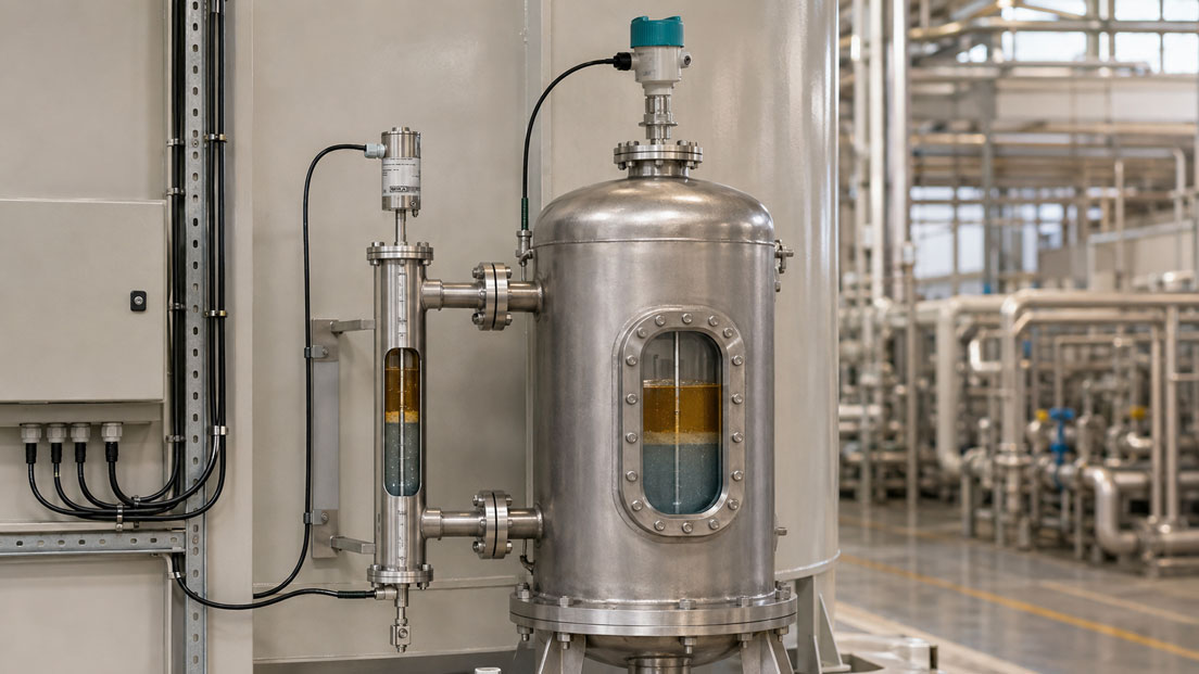
Separators, storage tanks and process vessels often contain two immiscible liquids. Typical examples include water beneath oil, condensate beneath fuel or an aqueous phase beneath an organic solvent. For a stable process, knowing only the total level in the vessel is not sufficient. It is also essential to know the height of the interface between the two liquids.
Incorrect interface measurement can result in valuable oil being discharged during dewatering, water entering a downstream process or a separator being operated outside its intended working range. Measurement becomes particularly challenging when an emulsion layer forms between the oil and water, densities fluctuate or deposits build up on the probe or guide tube.
Guided wave radar and float-based systems are among the technologies suitable for continuous oil-water interface measurement. An overview of suitable measuring methods can be found in the ICS category Continuous Level Measurement. Magnetostrictive transmitters, bypass indicators and other robust float solutions are summarised under WIKA KSR Kuebler Level Measurement Technology.
Table of Contents
- Distinguishing between total level and interface
- Which process data are required?
- How does guided wave radar work?
- When is TDR suitable for oil and water?
- How does measurement with two floats work?
- Correctly sizing density and floats
- Comparison of TDR and float systems
- Assessing emulsion, foam and transition layers
- Correctly planning probe length, installation and bypass
- Calibration, commissioning and diagnostics
- Typical interface measurement errors
- Practical example: Oil-water separator
- Which products and solutions are suitable?
- Conclusion
- Frequently asked questions
Distinguishing between total level and interface
In a vessel containing oil and water, there are at least two relevant levels:
- the total level at the surface between the gas space and the upper liquid,
- the interface between the upper and lower liquid phases.
For example, if a vessel contains 800 mm of water with 1,000 mm of oil above it, the oil-water interface is located 800 mm above the vessel bottom. The total level, however, is 1,800 mm. If the water layer rises while the total level remains unchanged, oil is displaced. A total level measurement alone would not detect this change.
Before selecting the instrument, it is therefore necessary to define which measured values are actually required:
| Measurement task | Required measured value | Typical purpose |
|---|---|---|
| Monitor vessel filling | Total level | Monitor overfilling and available volume |
| Drain water automatically | Oil-water interface | Control the dewatering valve |
| Balance both phases | Total level and interface | Calculate oil and water volumes separately |
| Monitor the emulsion layer | Multiple transitions or density profile | Assess separator performance and chemical dosing |
An interface measurement also does not automatically replace an independent overfill protection system or a separate point level switch. Whether additional safety equipment is required depends on the operational risk assessment and the requirements of the system.
Which process data are required?
Reliable selection begins with complete data for both liquids. The description “oil and water” alone is not sufficient because crude oil, lubricating oil, diesel, solvents and process oils can have very different properties.
At least the following information should be available for sizing:
- density of the upper and lower phases at minimum and maximum temperature,
- dynamic or kinematic viscosity of both liquids,
- electrical conductivity and relative permittivity, where available,
- temperature and pressure range,
- maximum and minimum height of the individual layers,
- expected thickness of an emulsion or transition zone,
- foam, gas bubbles, solids and deposits,
- chemical composition and material compatibility,
- tank height, nozzles, internal fittings, agitators and flow conditions,
- required output signals and integration into the control system.
The most unfavourable operating conditions are particularly important. The density of an oil can change with temperature, composition or absorbed water. The water layer may also contain salts, solids or chemicals. A measuring point that operates correctly with a clean reference medium will therefore not necessarily work reliably under actual process conditions.
How does guided wave radar work?
With guided wave radar, often referred to as TDR or Guided Wave Radar, short electromagnetic pulses are guided into the vessel along a rod, cable or coaxial probe. If the electrical properties of the surrounding medium change along the probe, part of the signal is reflected.
In an oil-water system, two relevant reflections can occur:
- at the surface between the gas space and the oil,
- at the interface between the oil and water.
The electronics calculate the distance to the respective layers from the signal travel time. Interface measurement requires a sufficient proportion of the signal to pass through the upper liquid so that the reflection from the lower phase can be evaluated clearly.
The main difference compared with non-contact radar measurement is that the signal is guided along a probe. This often makes the measurement less sensitive to inclined surfaces, narrow vessels or nearby internal fittings. However, the probe is in direct contact with the medium and can be affected mechanically or metrologically by heavy deposits.
When is TDR suitable for oil and water?
Oil above water is generally a favourable application for TDR because the two phases usually have distinctly different dielectric properties. However, the upper oil phase must allow the signal to pass through sufficiently. If the upper liquid is highly conductive or absorbs a large proportion of the signal, the surface reflection may become so dominant that the interface beneath it can no longer be detected reliably.
The following points are particularly important when sizing a TDR system:
Sufficient contrast between the phases
The reflection at the interface is caused by the difference in electrical properties. The greater this difference, the easier it is to detect the interface. If two liquids have similar properties, however, the interface echo may be very weak.
Minimum thickness of the upper layer
If the oil-water interface is very close to the upper product surface, the two reflections may overlap. The required minimum layer thickness depends on the instrument, probe, parameterisation and process conditions and must be checked for the specific device version.
Suitable probe design
| Probe design | Strengths | Points to consider |
|---|---|---|
| Rod probe | Mechanically stable and comparatively easy to clean | Sufficient installation space and vessel height required |
| Cable probe | Suitable for long measuring ranges and tall vessels | Check lateral movement, tensile forces and bottom anchoring |
| Coaxial probe | Very well-defined signal guidance and low influence from nearby internal fittings | Narrow gaps may become blocked by viscous or contaminated media |
Deposits and build-up
A thin, uniform film is not automatically critical. Thick, uneven or conductive deposits can, however, cause additional reflections, signal attenuation or an apparent extension of the probe. Cleanability and the tendency to form deposits must therefore be considered during the selection stage.
How does measurement with two floats work?
Float-based interface measurements use the buoyancy of the liquids. In a dual-float system, two differently designed floats are installed along a guide tube.
The upper float follows the surface of the lighter liquid and measures the total level. The second float sinks through the lighter oil phase but is supported by the denser water phase. It therefore follows the oil-water interface.
In a magnetostrictive level transmitter, the floats contain integrated magnets. A measurement pulse travels through a magnetostrictive wire inside the guide tube. At the position of a float, the interaction of the magnetic fields generates a mechanical torsional wave. The electronics calculate the float position from its travel time.
If the specific version supports multiple floats, the total level and interface can be measured with one sensor and transmitted to the control system, for example via HART or separate output signals.
Correctly sizing density and floats
For reliable interface measurement, each float must be suitable for the intended density range. In simplified terms, the following conditions apply:
Density of the total-level float < Density of the upper liquid
Density of the upper liquid < Density of the interface float < Density of the lower liquid
The interface float must therefore sink through the oil but obtain sufficient buoyancy on the water. In practice, more than the average float density is considered. The manufacturer adapts the shape, volume, mass, immersion depth and magnet position to the application.
Measurement becomes problematic when the densities of the two liquids approach each other. If, for example, the density of the oil phase increases due to water absorption, contamination or temperature changes, the interface float may sit higher within the oil phase. If the density of the water phase decreases at the same time, the available density difference becomes even smaller.
For sizing, the following limiting conditions should therefore be specified in addition to the nominal values:
- maximum density of the upper phase,
- minimum density of the lower phase,
- complete temperature range,
- possible changes in concentration and composition.
Viscosity is also relevant. Highly viscous oil can delay the movement of the float. Wax, resin, sludge or sticky deposits may prevent the float from moving freely along the guide tube.
Comparison of TDR and float systems
| Criterion | Guided wave radar | Magnetostrictive dual-float system |
|---|---|---|
| Physical principle | Dielectric contrast and signal travel time | Density difference, buoyancy and float position |
| Total level and interface | Evaluation of multiple reflections | Two suitably designed floats |
| Influence of density changes | Usually little direct influence | Can shift immersion depth and measuring position |
| Influence of electrical properties | Decisive for signal transmission and reflection | Largely irrelevant to the measuring principle |
| Foam on the surface | Depends on structure and signal absorption | Float usually sinks through light foam to the liquid surface |
| Emulsion layer | Broad or ambiguous echo possible | Float may settle within the density transition zone |
| Build-up | Can cause false echoes and attenuation | Can mechanically block the float |
| Long measuring ranges | Can be implemented effectively with a suitable cable probe | Guide tube, stability and installation effort must be considered |
| Commissioning | Parameterisation and echo profile required | Float sizing is decisive; parameterisation is often straightforward |
| Diagnostics | Echo curve, signal quality and reflection positions | Position values, plausibility and mechanical freedom of movement |
Neither method is fundamentally superior in every application. TDR is often advantageous when densities fluctuate but a clear dielectric contrast is present. A dual-float system is particularly robust when the densities are reliably known and electrical properties, foam or vapour vary significantly.
Assessing emulsion, foam and transition layers
In real separators, the boundary between oil and water is not always sharply defined. Pumps, agitators, surfactants or high flow velocities can create an emulsion zone. Density and electrical properties change continuously within this layer.
With TDR, a broad emulsion layer can produce an extended, attenuated or multiple reflection. The instrument must then decide which point is to be output as the interface. Depending on the parameterisation and signal processing, this may be the upper edge, the lower edge or the strongest echo within the transition zone.
An interface float settles at the position where buoyancy and weight are in equilibrium. In a broad density transition zone, this position may be located within the emulsion. It does not necessarily correspond to the visible lower or upper edge of the emulsion layer.
It must therefore be defined in advance what the process means by “interface”:
- the beginning of the water-rich phase,
- the end of the oil-rich phase,
- the centre of the emulsion zone,
- a specific density or electrical property,
- the permissible control position for the dewatering valve.
If the complete profile of oil, emulsion, water and sediment must be determined rather than a single interface, a simple two-point interface method may be insufficient. Additional sampling, multiple measuring principles or specialised density-profile measurement systems may then be required.
Correctly planning probe length, installation and bypass
Direct installation from above
A TDR probe or magnetostrictive guide tube can be installed directly into the vessel from above. The active measuring length must cover the entire relevant area. At the same time, the upper and lower dead zones, vessel bottom, internal fittings and the required removal clearance above the tank must be taken into account.
A rod probe must not be installed under mechanical stress or subjected to lateral loads caused by vessel movement. Cable probes must not strike internal fittings uncontrollably. In the presence of flow, turbulence or a strong inlet stream, a stilling tube or another form of mechanical calming may be required.
Measurement in a bypass or reference chamber
An external reference chamber is connected to the vessel through an upper and a lower connection. Under stable conditions, the levels in the reference chamber correspond to those in the main vessel. The sensor and floats are readily accessible there and can often be maintained more easily.
For interface measurement, however, both liquid phases must be able to enter and leave the chamber freely. A blocked lower connection can cause the water layer in the reference chamber to differ from the actual interface in the vessel. Connections that are too small, long pipes or high viscosity can also delay the response.
Where there is strong flow in the main vessel, the bypass can stabilise the measurement. At the same time, it must be checked whether the medium cools, degasses or separates differently in the external chamber than in the process vessel.
Calibration, commissioning and diagnostics
Commissioning should not be performed only with an empty and completely full vessel. For interface measurement, the total level and interface must be tested separately.
- Define reference levels: Clearly document the process connection, probe start, vessel bottom and zero point.
- Assign measuring ranges: Define which output transmits the total level and which output transmits the interface.
- Check the empty condition: Verify the zero point, dead zones, probe end and possible fixed false echoes.
- Fill with water only: Check the lower phase and the basic sensor function.
- Add oil gradually: Compare the total level and interface with an independent reference.
- Approach actual temperatures: Assess density changes, viscosity and signal stability.
- Check dynamic operation: Test inlet flow, dewatering, pumps and turbulence under real operating conditions.
- Verify alarm plausibility: Simulate signal loss, implausible layer thicknesses and limit-value violations.
A sight glass, defined sampling points, manual gauging or controlled filling with known volumes can be used as a reference. With a bypass, it must also be checked whether its indication follows the main vessel without delay.
For TDR, the echo profile should be stored under several operating conditions. This makes it possible to identify later changes in reflections, signal strength or false echoes. For float systems, the functional test should include free movement, the correct sequence of the floats and the plausibility of both position values.
Typical interface measurement errors
| Error | Possible consequence | Suitable measure |
|---|---|---|
| Only the total level is measured | A rising water layer remains undetected | Provide a separate interface measured value |
| Density specified only at room temperature | Interface float operates incorrectly at process temperature | Specify the density range for all temperatures |
| Upper phase attenuates the TDR signal too strongly | Interface echo is not detected | Check electrical properties or consider the float principle |
| Emulsion treated as a sharp boundary | Measured value does not match the operational expectation | Define the interface and emulsion width |
| Incorrect float installed | Float remains on the oil surface or sinks to the bottom | Size the float using both density ranges |
| TDR probe too short or dead zone overlooked | Interface is not detected in critical areas | Check the active measuring length and all dead zones |
| Deposits not considered | False echoes or blocked float | Provide a cleaning strategy and suitable design |
| Lower bypass connection blocked | Interface in the bypass differs from that in the tank | Inspect the connections and design them for flushing |
| Total level and interface interchanged in the PLC | Valve is controlled using the wrong measured value | Check signal assignment, scaling and designation |
Practical example: Oil-water separator
Oil-contaminated process water is separated in an industrial separator. The water phase is at the bottom, with an oil layer above it. The total level must be kept constant while a valve at the bottom of the vessel discharges the water phase in a controlled manner.
The density of the oil fluctuates depending on its composition and temperature. An emulsion layer with a thickness of 50 to 150 mm forms intermittently between the oil and water. Sludge and solids can also settle in areas with little movement.
For a TDR solution, a rigid rod probe is installed from above. The dielectric contrast between the oil and water phases is generally good. During commissioning, however, the echo profile shows that the interface reflection broadens when substantial emulsion forms. For this reason, both the measured value and the signal quality are monitored.
The control system does not open the dewatering valve immediately in response to every small change in the measured value. Instead, a permissible interface range, a time delay and a plausibility check using the total level are configured. A sudden change in the interface value while the process remains unchanged is treated as a diagnostic event.
A magnetostrictive dual-float system is assessed as an alternative. The upper float is sized for the minimum density of the oil phase. The interface float must sink through the oil but float reliably at the minimum expected density of the water phase.
Because the emulsion zone is sometimes broad, the float would also not provide a universally valid transition point. For process control, it is therefore defined that the measurement represents the position of a specified average density. Regular samples taken at the lower drain confirm whether the selected shut-off point prevents oil from being discharged with the water.
The final decision between TDR and float measurement is based on density fluctuations, the tendency to form deposits, maintenance accessibility and diagnostic requirements. In particularly critical systems, a combination of continuous interface measurement, a separate point level switch and sampling may be appropriate.
Which products and solutions are suitable?
SITRANS LG
The SITRANS LG operates according to the guided wave radar principle. The series is designed for continuous level, volume and interface measurement. For liquid and interface applications, a suitably configured version with an appropriate rod, cable or coaxial probe is particularly relevant.
When selecting the instrument, the probe design, measuring length, process connection, temperature, pressure, materials and electrical properties of both liquids must be considered together. During commissioning, the echo curve and the clear assignment of the total level and interface are particularly important.
WIKA FLM-S, FLM-T and FLM-P
The WIKA FLM-S, FLM-T and FLM-P models are magnetostrictive level transmitters for high-accuracy continuous liquid measurement. In a version designed for multiple floats, the total level and interface can be measured simultaneously.
The system is sized for the specific application. The floats, guide tube, process connection and materials must be suitable for the densities, viscosity, temperature, pressure and chemical composition of both media.
WIKA BZG Reference Chamber
The WIKA BZG reference chamber is connected to the side of the vessel through at least two process connections. Depending on the version, it can be combined with suitable level sensors or guided wave radar.
An external reference chamber often simplifies maintenance, retrofitting and mechanical calming of the measuring point. For oil-water interface measurement, the connection positions, pipe cross-sections, drainage, venting and possible deposits must be planned particularly carefully.
ICS Schneider Messtechnik provides support in selecting the measuring principle, assessing density and dielectric properties, sizing the probe and floats and configuring signal assignment, parameterisation and integration into a PLC or process control system.
Conclusion
Reliable oil-water interface measurement begins with a clear distinction between the total level, the actual phase boundary and any possible emulsion zone. The appropriate measuring principle can only be selected once it has been defined which transition is relevant to process control.
Guided wave radar uses the difference in dielectric properties. It is particularly suitable when the upper phase allows the signal to pass through sufficiently and a clear echo is generated at the interface. Magnetostrictive dual-float systems, by contrast, operate on the basis of the density difference and are largely independent of conductivity and permittivity.
TDR is sensitive to unsuitable electrical properties, overlapping reflections and substantial build-up. Float systems require sufficiently stable density differences and unrestricted mechanical movement. With both methods, a broad emulsion layer can result in the measurement of a defined point within the transition zone rather than a sharp boundary.
The correct solution therefore depends on density, dielectric contrast, emulsion behaviour, deposits, tank geometry, maintenance access and the required diagnostic functions. Verification under actual operating conditions is essential for critical separators and dewatering processes.
Frequently asked questions about oil-water interface measurement
Can a standard level sensor detect water beneath oil?
Not automatically. Many sensors detect only the upper product surface. To measure water beneath oil, the instrument must be explicitly suitable for interface measurement and correctly sized for both liquids.
Why is guided wave radar suitable for oil and water?
Oil and water usually have distinctly different electrical properties. This can generate an additional reflection at the interface. However, the oil phase must allow enough of the measurement signal to reach the water phase.
What density is required for an interface float?
The float must be designed to suit both liquids. It must sink through the lighter upper phase but obtain sufficient buoyancy on the denser lower phase. The specific design is based on the complete density ranges and process conditions.
Can an emulsion layer be measured precisely?
With a broad emulsion, a single interface measurement usually provides only a characteristic point within the transition zone. If the complete thickness or composition of the emulsion must be determined, additional measurements or specialised profiling methods are required.
Does foam affect interface measurement?
Foam on the upper surface can affect total level measurement. A suitably designed float often sinks through light foam to the liquid surface. With TDR, the influence depends on the density, moisture content, structure and electrical properties of the foam.
Is a bypass suitable for interface measurement?
A bypass can stabilise the measurement and simplify maintenance. However, it operates reliably only when both phases can communicate freely with the main vessel and the connections are not blocked by sludge, wax or deposits.
How can the measurement be checked during commissioning?
The total level and interface should be compared with independent references, such as a sight glass, sampling or controlled filling. For TDR, the echo profile must also be checked; for float systems, the free movement and correct signal assignment of both floats must be verified.
Which measurement method is better when the oil density fluctuates?
When density fluctuates significantly, TDR can be advantageous, provided that the electrical properties permit reliable interface reflection. With stable densities and changing conductivity or foam formation, a suitably designed float system may be more robust.