


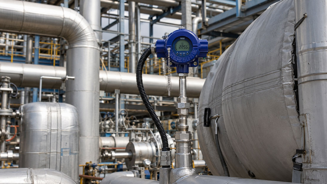
Thermocouples are frequently used in the chemical, petrochemical, power-generation and process industries at high temperatures and during rapid temperature changes. However, when the measuring point is located in a potentially explosive atmosphere, selecting the thermocouple type and measuring range alone is not sufficient.
Explosion-protection suitability applies to the complete measuring chain: measuring tip, sheath or thermowell, connection head, terminal block or head-mounted transmitter, cable gland, connecting cable, Ex barrier and evaluation instrument must be technically compatible and correctly documented.
Errors occur particularly during modifications, for example when an approved terminal block is subsequently replaced by an arbitrary transmitter, a cable gland is changed or the permissible ambient temperature of the connection head is not taken into account. The marking of an individual component does not automatically prove the suitability of the complete temperature measuring point.
Table of contents
- Why the complete Ex measuring chain must be considered
- Assigning the Ex zone, equipment category and EPL
- Intrinsic safety or flameproof enclosure?
- Selecting the thermocouple and measuring-point design
- Correctly designing the connection head and cable gland
- Head-mounted transmitter, barrier and current loop
- Temperature class and surface temperature
- Thermowell, sheath material and process loading
- Compensating cable, polarity and shielding
- Marking and documentation
- What must be considered during modifications
- Systematic commissioning
- Typical design and connection errors
- Practical example: Temperature measurement on a reactor
- Which measuring instruments / products are suitable?
- Conclusion
- Frequently asked questions about thermocouples in hazardous areas
Why the complete Ex measuring chain must be considered
An explosion-protected temperature measuring point consists of more than the thermocouple itself. Depending on the design, it includes:
- thermocouple and measuring junction
- sheath, neck tube or thermowell
- process connection
- connection head with terminal block or transmitter
- cable gland and blanking plugs
- compensating or thermocouple cable
- Ex barrier, isolating power supply or intrinsically safe input
- PLC, display or process control system
All components must be suitable for the intended application. Relevant factors include the zone, gas or dust group, type of protection, temperature class, ambient temperature and electrical connection values.
An ATEX-approved temperature transmitter does not automatically make an unsuitable connection head explosion-protected. Conversely, an approved Ex connection head must not be fitted with an arbitrary transmitter or a different cable gland without verification.
Assigning the Ex zone, equipment category and EPL
The operator must first define which potentially explosive atmosphere may occur at the measuring point. This determines the required equipment protection level.
| Area | Zone | Typical required EPL |
|---|---|---|
| Gas, vapour or mist | Zone 0 | Ga |
| Gas, vapour or mist | Zone 1 | Gb |
| Gas, vapour or mist | Zone 2 | Gc |
| Combustible dust | Zone 20 | Da |
| Combustible dust | Zone 21 | Db |
| Combustible dust | Zone 22 | Dc |
The sensor tip and connection head may be located in different areas. For example, the measuring tip may extend into Zone 0 while the connection head is installed in Zone 1. The marking of the selected equipment version must correspond exactly to this installation situation.
The gas group, for example IIA, IIB or IIC, or the corresponding dust group must also be considered. Approval for a less demanding group must not simply be transferred to a more demanding atmosphere.
Intrinsic safety or flameproof enclosure?
Intrinsic safety Ex i and flameproof enclosure Ex d are frequently used for industrial thermocouple measuring points. The two concepts use different protection principles.
Intrinsic safety Ex i
In an intrinsically safe circuit, voltage, current and power are limited so that no ignitable energy can occur under the defined fault conditions.
The electrical safety parameters of the connected devices form part of the design. In simplified terms, the maximum output values of the associated apparatus must be compatible with the permissible input values of the field device. The capacitance and inductance of the connecting cable must also be considered.
A separate barrier is not necessarily required in every system. It may already be implemented as a galvanic isolator, Ex input card or intrinsically safe transmitter power supply. The decisive factor is the documented verification of the complete circuit.
Flameproof enclosure Ex d
With Ex d, a possible ignition inside a suitably designed enclosure must not be transmitted to the surrounding atmosphere. The connection head, threads, cover, cable glands and blanking plugs form a certified system.
Ex d enclosures must not be modified arbitrarily or fitted with unverified entries. Opening the connection head in the hazardous area is also governed by the approval, operating instructions and operational safety rules.
Selecting the thermocouple and measuring-point design
The thermocouple type is selected according to the temperature range, atmosphere, accuracy and long-term stability. Types K, N and J are frequently used in the process industry, while noble-metal thermocouples are used at very high temperatures.
The design of the measuring junction is also important:
- isolated measuring junction
- measuring junction connected to the sheath
- exposed measuring junction
- single or dual thermocouple
A measuring junction connected to the sheath can respond particularly quickly. However, the electrical connection between the thermocouple and sheath may result in potential differences and grounding influences. With an isolated thermocouple, galvanic isolation from the sheath is better, but the response can be somewhat slower depending on the design.
In a hazardous area, this decision must not be based solely on response time. The measuring-junction design must correspond to the approved sensor version and electrical protection concept.
Correctly designing the connection head and cable gland
The connection head protects the terminal block or transmitter against environmental influences and is also part of the explosion-protection concept.
The following in particular must be checked during selection:
- Ex marking and type of protection
- permissible ambient temperature
- ingress protection against dust and moisture
- material and corrosion resistance
- space required by the head-mounted transmitter
- cable entry and cable diameter
- equipotential bonding or grounding connection
The cable gland must match the type of protection, connection head and cable used. An Ex-approved gland may lose its protective function if the cable diameter lies outside the approved clamping range.
Unused entries must be closed using suitable approved blanking plugs. An ordinary plastic plug is not an equivalent replacement.
Head-mounted transmitter, barrier and current loop
A head-mounted transmitter converts the low thermoelectric voltage into a robust output signal. A 4–20 mA signal, optionally with HART communication, is frequently used.
The transmitter provides several advantages:
- cold-junction compensation directly in the connection head
- linearisation of the thermocouple signal
- lower susceptibility to interference over long cable runs
- configurable measuring ranges
- sensor-break and fault diagnostics
For an intrinsically safe installation, the specific Ex version of the transmitter must be selected. In addition to its suitability for the thermocouple, its intrinsically safe connection values, permissible ambient temperature and installation conditions inside the connection head must be checked.
The transmitter is then supplied via a suitable isolating power supply or certified intrinsically safe analogue input. The electrical verification covers the transmitter, associated apparatus and the cable between them.
A 4–20 mA loop check can test the wiring, barrier, PLC input and scaling. However, it replaces neither the intrinsic-safety verification nor the temperature calibration of the sensor.
Temperature class and surface temperature
The temperature class of Ex equipment describes the maximum permissible surface temperature and must not be confused with the measuring range of the thermocouple.
A thermocouple may measure a process temperature of several hundred degrees Celsius, while the connection head must remain significantly cooler due to the required temperature class.
Several factors influence the surface temperature:
- process temperature
- heat conduction through the thermowell and neck tube
- ambient temperature
- self-heating of the transmitter
- mounting position and air circulation
- thermal insulation of the pipe
A sufficient neck length may be required to thermally isolate the connection head from the process. If a hot pipe is insulated right up to the connection head, the permissible housing or transmitter temperature may be exceeded.
The permissible temperature class and associated operating conditions can be found in the complete marking and supplementary Ex operating instructions.
Thermowell, sheath material and process loading
Explosion protection does not replace the mechanical and chemical design of the measuring point. The thermowell or sheath must permanently withstand pressure, flow, temperature, vibration and the process medium.
Important selection criteria include:
- process pressure and possible pressure surges
- flow velocity
- insertion length and diameter
- vibration and resonance loading
- corrosion, abrasion and diffusion
- required response time
A long, thin thermowell stem does not automatically improve the measurement. In rapidly flowing media, it may be exposed to considerable bending and vibration loads. Depending on the application, a thermowell calculation may be required.
The compatibility of the sheath or thermowell material with the medium must be confirmed by the plant operator or based on reliable process data.
Compensating cable, polarity and shielding
If the thermocouple signal is transmitted without a head-mounted transmitter, the correct thermocouple or compensating cable must be used. An ordinary copper cable creates additional junctions and can cause significant measuring errors.
The following are important:
- correct cable type for the thermocouple
- correct polarity
- suitable temperature class of the cable
- Ex-compliant routing and entry
- separation from power and motor cables
- shield connection in accordance with the system concept
The colour coding may differ depending on the applicable standard. The polarity should therefore not be assumed solely on the basis of a familiar cable colour.
With a head-mounted transmitter, the thermocouple signal is carried only over a short distance inside the connection head. A less interference-sensitive 4–20 mA signal can be used downstream of the transmitter.
Marking and documentation
The relevant documents for the Ex measuring point must be clearly assignable to the installed version. These typically include:
- rating plate and complete Ex marking
- EU declaration of conformity
- ATEX or IECEx certificate
- operating instructions and supplementary Ex operating instructions
- electrical verification of the intrinsically safe circuit
- connection and terminal diagram
- material and process data
- calibration and test certificates
An “X” following a certificate number indicates special conditions for safe use. These conditions must be considered during planning and operation.
A calibration certificate confirms metrological characteristics. It replaces neither the Ex approval nor verification of correct installation.
What must be considered during modifications
Modifications to an Ex temperature measuring point must not be performed in the same way as modifications to an ordinary sensor. Even minor changes can affect the approved configuration.
Critical changes include, for example:
- replacing the terminal block with a different transmitter
- replacing the cable gland or blanking plug
- changing the connection head
- changing the neck length or insertion length
- using a different thermocouple or dual thermocouple
- changing the shielding or grounding
- replacing the barrier or isolating power supply
Before a modification, it must be checked whether the new combination is covered by the certificate and manufacturer documentation. If this is not the case, a new technical assessment or a different certified equipment version may be required.
Systematic commissioning
- Identify the measuring point: Check the zone, EPL, substance group and temperature class.
- Compare the rating plate: Verify the marking against the design documents and certificate.
- Check the mechanical installation: Inspect the process connection, insertion length, thermowell and neck length.
- Inspect the connection head: Check the cover, seal, cable gland and blanking plugs.
- Check the wiring: Verify the thermocouple type, polarity, shielding and terminal assignment.
- Verify the Ex circuit: Document the transmitter, barrier and cable parameters.
- Check the scaling: Verify the measuring range, fault response and PLC indication.
- Perform a plausibility check: Compare the measured value with the process condition or a reference measurement.
- Complete the documentation: Assign the equipment data and test results to the measuring point.
Typical design and connection errors
| Error | Possible consequence | Better approach |
|---|---|---|
| Only the sensor has Ex approval | The connection head or transmitter does not match the zone | Check the complete equipment configuration |
| An arbitrary cable gland is installed | The type of protection or ingress protection is invalidated | Use an approved gland with the correct clamping range |
| The temperature class is confused with the measuring range | Impermissible surface temperature at the connection head | Assess heat conduction and ambient temperature |
| No calculation of the Ex i circuit | Intrinsic safety has not been verified | Document the electrical parameters including the cable |
| Incorrect compensating cable is used | Temperature-dependent measuring error | Select a cable suitable for the thermocouple type |
| Polarity is reversed | The measured value changes in the wrong direction or is implausible | Check the terminal marking and polarity |
| Pipe insulation extends up to the connection head | The permissible transmitter or housing temperature is exceeded | Provide sufficient thermal isolation |
| The transmitter is replaced later without verification | The approval and circuit verification are no longer valid | Use only a documented and approved configuration |
Practical example: Temperature measurement on a reactor
The product temperature in a chemical reactor is to be measured up to 450 °C. On the process side, the measuring tip is located in an area with demanding equipment-protection requirements, while the connection head is installed in Zone 1.
A type K process thermocouple with a suitable thermowell and sufficiently long neck extension is selected. This keeps the connection head within its permissible ambient-temperature range despite the high process temperature.
A 4–20 mA transmitter approved for the thermocouple and the Ex i application is installed in the head. The current loop is routed to the PLC via a galvanically isolated Ex transmitter power supply.
During review of the original design, it is found that the pipe insulation was intended to extend directly below the connection head. This would have resulted in a significantly higher housing temperature. The insulation is therefore modified and the neck length is assessed again from a thermal perspective.
Before commissioning, the rating plate, certificates, special conditions, transmitter parameters, isolating power supply and cable data are documented. A plausibility check of the complete measuring chain is then carried out.
The example shows that electrical intrinsic safety is not the only decisive factor. Heat transfer from the process can also affect the permissible Ex configuration.
Which measuring instruments / products are suitable?
The thermocouples category contains different sensor designs for the process industry, mechanical engineering and high-temperature applications.
Suitable head-mounted and rail-mounted transmitters and accessories are available in the temperature transmitters and accessories for temperature sensors category.
WIKA TC12-B and TC12-M for process applications
The WIKA TC12-B and TC12-M thermocouples are designed for installation in a thermowell or base module.
Depending on the configuration, different connection heads, transmitters and Ex versions are available. For selection, the process connection, thermowell, zone, EPL, temperature class and required output signal must be defined completely.
SITRANS TS500 for modular process measuring points
The SITRANS TS500 type 3G is a modular temperature sensor with an extension for industrial process applications.
Depending on the version, intrinsically safe and flameproof variants with ATEX or IECEx approval are available.
Straight thermocouples with connection head
The straight thermocouples in accordance with EN 50446 are suitable for industrial high-temperature measurements with a metallic thermowell and can be supplied with an integrated temperature transmitter.
Whether an Ex version is available and suitable for the specific zone must be checked based on the complete configuration.
WIKA T16 for thermocouples and 4–20 mA
The WIKA T16 processes signals from common thermocouples and converts them into a 4–20 mA signal.
Corresponding Ex versions are available for hazardous areas. The specific order variant, intrinsically safe connection values and permissible installation situation are decisive.
ICS Schneider Messtechnik assists with designing the complete temperature measuring point. The required information includes the thermocouple type, measuring range, process medium, pressure, flow, insertion length, zone, gas or dust group, temperature class, ambient temperature, type of protection and required output signal.
Conclusion: Explosion protection applies to the complete temperature measuring point
A thermocouple in a hazardous area must be considered as a complete system. The sensor, thermowell, connection head, transmitter, cable gland, cable and Ex barrier must all match the intended zone and type of protection.
For intrinsically safe circuits, the electrical safety parameters of all components, including the cable, must be verified. With flameproof versions, the housing, threads and cable entries must not be modified arbitrarily.
The temperature class describes the permissible surface temperature and not the measuring range of the thermocouple. High process temperatures, thermal insulation and an insufficient neck extension can cause the connection head to heat up beyond its permissible limit.
The thermowell material, flow loading, compensating cable, polarity and mechanical installation also influence safety and measuring quality.
Modifications should therefore only be made after reviewing the certificates and manufacturer documentation. A clearly documented overall design prevents a seemingly minor change from invalidating the Ex suitability of the measuring point.
Frequently asked questions about thermocouples in hazardous areas
Does every thermocouple in a hazardous area require its own ATEX approval?
This depends on the sensor design, type of protection and equipment configuration. The documented verification of the complete measuring point for the intended zone is decisive.
Can a thermocouple be connected directly to an Ex barrier?
This is possible only if the input, circuit and sensor design are intended and assessed for this purpose. An Ex i head-mounted transmitter is frequently used instead.
What is the advantage of a head-mounted transmitter?
It provides cold-junction compensation and linearisation and converts the sensitive thermocouple signal into a more robust 4–20 mA signal.
Can an ordinary transmitter be installed in an Ex connection head?
Not automatically. The transmitter, connection head and installation configuration must be covered by the approval and manufacturer documentation.
Is the temperature class the same as the maximum measuring range?
No. The temperature class limits the surface temperature of the equipment. Depending on the version, the thermocouple can measure considerably higher process temperatures.
Why is the neck length important at high temperatures?
It reduces heat conduction from the process to the connection head and protects the transmitter, cable gland and housing against impermissibly high temperatures.
Can an ordinary copper cable be used as an extension?
When transmitting the thermocouple signal directly, a suitable thermocouple or compensating cable is required. Copper cables can cause additional measuring errors.
Which information does ICS Schneider require for the design?
The required information includes the zone, EPL, gas or dust group, temperature class, process and ambient temperature, medium, pressure, installation situation, thermocouple type, type of protection, output signal and existing barrier or PLC input card.