


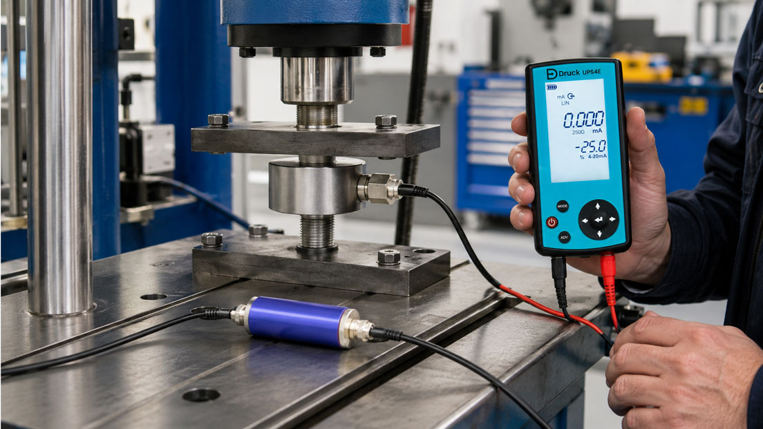
Force sensors are used in test benches, presses, joining fixtures, machines and lifting equipment. The mechanical design and measuring range are often the main considerations when selecting a sensor. However, the electrical output signal is at least equally important.
A conventional strain-gauge force transducer generally provides only a few millivolts and requires a stable bridge excitation voltage and a suitable measuring amplifier. By contrast, a sensor with a 4–20 mA or 0–10 V output can be connected directly to many PLC analogue inputs.
The easiest integration is not automatically the best solution. An unamplified mV/V signal can offer advantages for high-accuracy test benches. A 4–20 mA signal is usually more robust for long cable runs and industrial systems. A 0–10 V signal is particularly suitable for short distances within machines and control cabinets.
This article explains the differences and shows how the force sensor, measuring amplifier, PLC input and calibration can be combined to form a reliable measuring chain.
Table of contents
- How a strain-gauge force sensor works
- What an mV/V output signal means
- When a measuring amplifier is required
- Comparison of mV/V, 4–20 mA and 0–10 V
- When 4–20 mA is the best choice
- When 0–10 V is suitable
- Connecting a force sensor to a PLC
- Correctly implementing cabling, shielding and grounding
- Setting the zero point and scaling
- Distinguishing electrical signal testing from force calibration
- Typical errors when selecting the signal
- Practical example: Force monitoring on a joining fixture
- Which measuring instruments / products are suitable?
- Conclusion
- Frequently asked questions about force-sensor output signals
How a strain-gauge force sensor works
Many electrical force transducers use strain gauges. They are applied to an elastically deformable measuring body and connected to form a Wheatstone bridge.
When a tensile or compressive force acts on the measuring body, very small elastic deformations occur. This changes the resistance of the strain gauges. The measuring bridge generates an electrical differential voltage that is proportional to the applied force.
The sensor requires bridge excitation for this purpose. Typical measuring chains consist of:
- force transducer with a full strain-gauge bridge
- stable excitation voltage
- measuring amplifier or strain-gauge input
- display, data-acquisition system or PLC
The mechanical installation remains decisive regardless of the output signal. Transverse forces, bending moments, an inclined force application or an unsuitable mounting surface can cause greater errors than the downstream electronics.
What an mV/V output signal means
The sensitivity of a strain-gauge force transducer is frequently specified in millivolts per volt. A sensor with a rated output of 2 mV/V provides an output voltage of 2 mV per volt of bridge excitation at nominal force.
With an excitation voltage of 10 V, this results in:
2 mV/V × 10 V = 20 mV at nominal force
At half the nominal force, the ideal output signal is approximately 10 mV. In the unloaded condition, it is close to zero, although a small zero offset may be normal.
The mV/V ratio has the advantage that the sensor signal is referenced to the actual excitation voltage. If the bridge is excited with 5 V instead of 10 V, the absolute output voltage is halved, but the rated output in mV/V remains unchanged.
An mV/V sensor is particularly suitable when:
- high measuring accuracy is required
- fast dynamic acquisition is needed
- a suitable strain-gauge measuring amplifier is already available
- several sensors are connected to a specialised data-acquisition system
- excitation, filtering and scaling must be freely configurable
A conventional PLC voltage input for 0–10 V is normally unable to evaluate a signal of, for example, 0–20 mV with sufficient accuracy. A strain-gauge measuring amplifier is required between the sensor and the PLC.
When a measuring amplifier is required
The measuring amplifier supplies the strain-gauge bridge with a stable voltage and amplifies the small differential signal to an industrially usable range.
Depending on the version, it performs the following functions:
- bridge excitation
- amplification of the mV/V signal
- zero-point and span adjustment
- filtering and interference suppression
- galvanic isolation
- conversion to 4–20 mA or 0–10 V
The amplifier can be integrated directly into the sensor, in an in-line cable housing, on a DIN rail or in a measuring instrument.
Installing it close to the force transducer is often advantageous. The sensitive millivolt signal then only has to be transmitted over a short distance. A more robust standard signal is available downstream of the amplifier.
When selecting the amplifier, the rated output of the sensor, bridge resistance, excitation voltage and required output type must be compatible with the amplifier.
Comparison of mV/V, 4–20 mA and 0–10 V
| Characteristic | mV/V | 4–20 mA | 0–10 V |
|---|---|---|---|
| Signal level | Only a few millivolts | 4 to 20 mA | 0 to 10 V |
| Additional electronics | Strain-gauge amplifier or special measuring input required | Can often be connected directly to a PLC | Can often be connected directly to a PLC |
| Long cable runs | Only with careful design | Very suitable | Better suited to short or medium distances |
| Interference resistance | Sensitive | High | Moderate interference resistance |
| Cable faults detectable | Depends on the evaluation system | 4 mA live zero simplifies diagnostics | 0 V can represent either a measured value or a fault |
| Dynamic response | Potentially very high, depending on the amplifier | Depends on the integrated electronics | Depends on the integrated electronics |
| Typical application | Test bench and precision measurement | Industrial system and long cables | Machine and control cabinet |
The output signal does not change the mechanical accuracy of the force transducer. However, it influences how effectively the sensor signal can be transmitted, resolved, tested and processed by the control system.
When 4–20 mA is the best choice
The 4–20 mA signal is particularly robust against electrical interference and voltage drops over longer cable runs. The decisive variable is the loop current rather than the voltage at the PLC input.
The signal has a so-called live zero. The measuring range begins at 4 mA rather than 0 mA. This makes it easier to distinguish a valid zero-force value from a cable break or power-supply failure.
A typical scaling is:
| Force | Output signal |
|---|---|
| 0 kN | 4 mA |
| 50% of nominal force | 12 mA |
| 100% of nominal force | 20 mA |
4–20 mA is frequently suitable for:
- long cable runs
- machines with frequency converters and large motors
- remotely installed force transducers
- connection to PLCs and process control systems
- continuous process and overload monitoring
Before commissioning, it must be clarified whether the force sensor or measuring amplifier has an active or passive current output. The PLC input must be wired and supplied accordingly.
When 0–10 V is suitable
A 0–10 V signal can be connected easily to many PLC, controller and data-acquisition inputs. It is particularly suitable for short cable runs within a machine or control cabinet.
Its advantages include simple wiring and straightforward measurement using a multimeter. However, voltage drops, potential differences and induced interference voltages have a more direct influence on the measuring result than with a current loop.
0–10 V is frequently suitable when:
- the sensor, amplifier and PLC are located close together
- a suitable voltage input is already available
- fast analogue transmission is required
- the wiring is installed in a controlled EMC environment
With unipolar scaling, a compressive force of 0 to 100 kN can correspond to 0 to 10 V, for example. For tensile and compressive force measurements in both directions, a bipolar range such as −10 to +10 V may be more suitable. This requires a correspondingly suitable amplifier and analogue input.
Connecting a force sensor to a PLC
Before connection, it must be checked which signal the force transducer actually provides. Specifications such as “strain-gauge sensor”, “4-wire” or “10 V supply” are not sufficient on their own.
Direct mV/V signal
The PLC requires a special strain-gauge or load-cell module. It must be capable of exciting the bridge and evaluating the differential millivolt signal. Alternatively, an external measuring amplifier is connected upstream.
4–20 mA signal
The sensor or amplifier is connected to a current analogue input. The supply, load resistance, active or passive loop and common reference potentials must be considered.
0–10 V signal
The output signal is connected to a voltage input. The signal ground and supply potential must be implemented so that no unwanted equalising currents occur.
The sampling rate of the PLC must match the measuring task. Slow process monitoring requires a different temporal resolution from capturing a brief press-fitting force peak.
Correctly implementing cabling, shielding and grounding
The unamplified signal from a strain-gauge bridge is particularly sensitive to electromagnetic interference. The sensor cable should therefore be routed separately from motor, contactor and frequency-converter cables.
Important measures include:
- using a shielded and twisted sensor cable
- connecting the shield in accordance with the manufacturer’s instructions
- avoiding unnecessary cable extensions
- providing strain relief at the sensor
- avoiding additional terminal points where they are not required
- separating signal and power cables physically
A 6-wire system may be useful for long strain-gauge cables. Two additional sense wires measure the excitation voltage actually present at the sensor. The amplifier can therefore compensate for voltage drops along the cable.
Incorrectly connecting the shield at both ends can cause equipotential bonding currents. The implementation must therefore match the machine’s grounding and EMC concept.
Setting the zero point and scaling
After mechanical installation, a force transducer often indicates a small initial value. Possible causes include dead weight, preload, mounting stresses and electrical zero offset.
Zero adjustment must only be performed once the mechanical condition has been clearly defined. An actual preload must not accidentally be removed from the measurement.
The following applies to linear scaling:
Force = (measured signal − signal at zero force) × measuring span ÷ signal span
For a sensor with a range of 0 to 50 kN and a 4–20 mA output, for example:
- 4 mA = 0 kN
- 12 mA = 25 kN
- 20 mA = 50 kN
The PLC should check values below and above the regular signal range for plausibility. A current significantly below 4 mA may indicate a cable break, missing power supply or defective measuring amplifier.
Distinguishing electrical signal testing from force calibration
During troubleshooting, the mechanical sensor must be distinguished from the downstream signal chain.
Testing the PLC input
The UPS4E loop calibrator can generate defined currents such as 4, 12 and 20 mA. This allows the wiring, PLC input, display and scaling to be tested without applying a load to the force sensor.
The UPS4E can also measure the output current of a 4–20 mA measuring amplifier. With a voltage output, the output voltage can be checked.
Testing the measuring amplifier
To test the measuring amplifier completely, a defined strain-gauge bridge signal must be provided at its input. A suitable strain-gauge or mV/V simulator is required for this purpose.
A conventional loop calibrator does not replace this bridge simulation.
Mechanical calibration
During force calibration, the transducer is loaded with known, traceable forces. The complete measuring chain consisting of the sensor, amplifier, display and, where applicable, PLC is assessed.
Only this test identifies, among other things:
- sensitivity deviation of the force transducer
- hysteresis
- linearity deviation
- zero return
- mechanical installation influences
A correct 4–20 mA output therefore does not automatically prove that the force actually applied is being measured correctly.
Typical errors when selecting the signal
| Error | Possible consequence | Better approach |
|---|---|---|
| mV/V sensor connected directly to a 0–10 V input | No usable measured value or a highly noisy signal | Use a strain-gauge amplifier or special PLC module |
| 4–20 mA confused with 0–20 mA | Incorrect zero point and scaling | Clearly document the output range |
| Active output connected to a sourcing input | Malfunction or possible damage | Check whether the signal is active or passive |
| Long mV/V cable routed next to motor cables | Unstable and load-dependent interference signals | Install the amplifier close to the sensor and shield the cable |
| 0–10 V transmitted over a long distance | Errors caused by potential differences and voltage drops | Assess 4–20 mA or galvanic isolation |
| Only the PLC input is simulated electrically | A mechanical sensor fault remains undetected | Perform an additional force calibration |
| Zero adjustment performed under an unknown preload | The actual initial force is removed from the measurement | Define the mechanical zero condition beforehand |
Practical example: Force monitoring on a joining fixture
A maximum press-fitting force of 20 kN is to be monitored on a joining fixture. The force transducer is located directly at the press, while the PLC is approximately 25 m away in the control cabinet.
A force sensor with a direct mV/V signal is initially planned. However, the long sensor cable would have to be routed through a cable duct containing motor and valve cables.
For the final design, a strain-gauge force transducer with a cable measuring amplifier mounted close to the sensor is selected. The amplifier converts the bridge signal into 4–20 mA.
The PLC is scaled as follows:
- 4 mA = 0 kN
- 20 mA = 25 kN
The measuring range therefore provides reserve above the normal maximum press-fitting force. A warning is triggered at 18 kN and shutdown occurs at 22 kN.
During commissioning, a loop calibrator is first used to check whether 4, 12 and 20 mA are displayed correctly by the PLC as 0, 12.5 and 25 kN. The complete measuring chain is then loaded with defined reference forces.
This separation allows errors in the PLC scaling to be distinguished clearly from errors in the mechanical force measurement.
Which measuring instruments / products are suitable?
The force sensors, force measuring instruments and other mechanical sensors category contains solutions for mechanical engineering, test benches, automation and industrial process monitoring.
A selection of force transducers for tensile and compressive forces can be found in the tension and compression force transducers category.
WIKA F2812 for compact tension and compression force measurements
The WIKA F2812 is a compact tension and compression force transducer for measuring ranges from 0 to 50 N up to 0 to 1,000 N.
It is suitable for testing, joining and monitoring tasks in which the force transducer is installed directly in the load path. The output signal can be processed using suitable evaluation electronics.
WIKA F1222 for very confined installation spaces
The WIKA F1222 force transducer is designed for low installation heights and compressive-force measurements from low nominal forces.
It can optionally be combined with an in-line cable amplifier that provides a 4–20 mA or 0–10 V signal for further evaluation.
WIKA B1940 for converting mV/V
The WIKA B1940 amplifies the signal from a strain-gauge measuring bridge and converts it, depending on the version, into 0/4–20 mA or 0–10 V.
Its compact design and IP67 ingress protection enable installation close to the force transducer. This keeps the interference-sensitive mV/V signal path short.
WIKA E3906 for portable mV/V measurements
The WIKA E3906 strain-gauge handheld indicator is suitable for the portable display of force transducers and load cells with an mV/V output.
It is particularly suitable for service applications, test setups and applications that do not require permanent PLC integration.
UPS4E for the 4–20 mA signal chain
The UPS4E loop calibrator can measure and simulate 4–20 mA signals. This allows the measuring amplifier, wiring, PLC input and scaling to be tested selectively.
ICS Schneider Messtechnik assists with selecting the force transducer, measuring range, output signal, amplifier, display and calibration. The required information includes tensile or compressive force, maximum overload, dynamic response, installation space, cable length, environmental conditions and available PLC inputs.
Conclusion: The output signal must match the complete force measuring chain
An mV/V force transducer provides a flexible and precise basis for test benches and demanding measuring systems. However, it requires suitable bridge excitation and a strain-gauge measuring amplifier.
For long cable runs, industrial interference sources and direct PLC connection, 4–20 mA is frequently the most robust solution. The live zero also simplifies the detection of electrical faults.
A 0–10 V signal is easy to integrate and is particularly suitable for short signal paths within a machine or control cabinet.
With all versions, the signal type, supply, input resistance, scaling, shielding and required dynamic response must be coordinated.
An electrical signal test checks the wiring and evaluation system. Whether the force transducer measures the actual force correctly can only be demonstrated by mechanically calibrating the complete measuring chain.
Frequently asked questions about force-sensor output signals
Can an mV/V force sensor be connected directly to a PLC?
Only if the PLC has a special strain-gauge or load-cell module. A measuring amplifier is required for a conventional 0–10 V or 4–20 mA input.
What does a sensitivity of 2 mV/V mean?
At nominal force, the sensor provides an output voltage of 2 mV per volt of excitation voltage. With a bridge excitation of 10 V, the output is therefore 20 mV.
Which signal is suitable for long cables?
4–20 mA is generally the most suitable because cable resistance and induced interference voltages have comparatively little influence on the loop current.
Is 0–10 V faster than 4–20 mA?
Not necessarily. The actual bandwidth depends on the sensor, measuring amplifier, filtering and analogue input.
What is the difference between an active and passive 4–20 mA output?
An active output generates the loop current using its own power supply. A passive two-wire output requires an external loop supply.
Can the UPS4E test an mV/V force sensor?
Not completely. It is suitable for testing 4–20 mA signals and PLC inputs. A suitable mV/V simulator or strain-gauge test setup is required for a strain-gauge bridge.
How is a force sensor calibrated?
The sensor is loaded with known reference forces. The display or output signal is assessed at several measuring points with increasing and often also decreasing force.
Why does the sensor not indicate exactly zero without a load?
Possible causes include dead weight, preload, mounting stresses, temperature and the electrical zero offset of the strain-gauge bridge.
Which information does ICS Schneider require for selection?
The required information includes the measuring direction, nominal force, possible overload, static or dynamic application, installation situation, cable length, required output signal, available PLC input and required accuracy.