


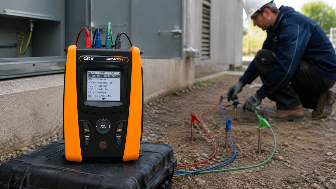
An effective earthing system is an essential part of protection against electric shock, overvoltages and fault currents. The condition of the earth electrode must be assessed regularly, particularly in TT systems, outdoor installations, construction sites, industrial buildings and lightning-protection systems.
Many modern installation testers include a function for measuring earth resistance. Nevertheless, not every measuring method produces the same value. Measurements using auxiliary probes, loop measurements via the power supply network and earth clamps measure different current paths.
An unusually low measured value is therefore not automatically proof of a particularly effective earth electrode. Parallel pipes, foundation earth electrodes, cable shields or additional electrodes can influence the measured value. Conversely, unsuitable probe spacing, dry soil or a poorly positioned auxiliary probe can produce an excessively high or unstable value.
This article explains the most important measuring methods and shows when an installation tester is sufficient, when auxiliary probes are required and when a specialised earth and soil resistivity tester is the better choice.
Table of contents
- What is actually measured during an earth resistance test
- Why earth resistance is particularly important in a TT system
- When an installation tester is sufficient
- Three-pole earth resistance measurement using auxiliary probes
- Correctly applying probe spacing and the 62% method
- Limitations of the two-pole method
- Parallel paths and external earth connections
- Selective earth resistance measurement without disconnection
- Earth resistance measurement using a clamp
- Determining the earth resistance via the fault loop
- Soil moisture, temperature and seasonal influences
- Safety when installing probes and disconnecting the earth electrode
- Documenting measured values traceably
- Typical measuring errors and their causes
- Practical example: Differing measured values in a TT installation
- Which measuring instruments / products are suitable?
- Conclusion
- Frequently asked questions about earth resistance measurement
What is actually measured during an earth resistance test
In simplified terms, earth resistance describes the resistance between an earth electrode and the sufficiently remote reference potential of the earth. It does not consist solely of the metallic resistance of the electrode.
The following factors are particularly important:
- contact resistance between the earth electrode and the soil
- specific resistivity of the surrounding soil
- shape, length and installation depth of the earth electrode
- number and spacing of multiple earth electrodes
- moisture, temperature and compaction of the soil
- parallel metallic connections to earth
The largest proportion of the resistance often occurs not in the metal of the earth electrode but in the surrounding soil. The current spreads spatially from the electrode through the ground. As the distance increases, the area of soil carrying the current becomes larger, so the additional resistance contribution becomes progressively smaller.
For a correct measurement, the test instrument must therefore pass a test current through the earth electrode and the soil while simultaneously measuring the voltage drop against a reference potential that is influenced as little as possible.
An ordinary ohmmeter is not suitable for this purpose. It only measures the resistance between its two terminals and cannot determine the resistance of the soil without a suitable return-current path.
Why earth resistance is particularly important in a TT system
In a TT system, the consumer installation has its own installation earth electrode. The protective conductor of the installation is not connected directly to the earthed star point of the supply network. In the event of a fault, the fault current therefore returns through the installation earth electrode, the soil and the supply network earth electrode.
Because this current path usually has a significantly higher resistance than the metallic fault loop of a TN system, residual current devices are generally used in TT systems.
The following condition is frequently used to coordinate the earthing system and the RCD:
RA × IΔn ≤ UL
The variables mean:
- RA: resistance of the earth electrode including the associated protective-conductor path
- IΔn: rated residual operating current of the residual current device
- UL: permissible touch voltage, usually 50 V AC
A lower permissible touch voltage may apply in special locations. The specific protection concept and the applicable standards are always decisive.
The purely calculated condition may result in relatively high permissible earth resistance values. In practice, however, measurement uncertainty, seasonal fluctuations, corrosion, ageing and operational safety margins must also be considered.
A universal limit of, for example, 10 Ω therefore does not apply to every earthing system. The permissible or target value depends on whether the system is used for protective earthing, lightning protection, functional earthing, a high-voltage installation or a TT system.
When an installation tester is sufficient
An installation tester is useful when earth resistance measurement forms part of a complete electrical installation test. In addition to the earth resistance, it can be used to test protective-conductor continuity, insulation resistance, loop impedance and RCD tripping, for example.
Depending on the instrument, different earth-measuring functions may be available:
- measurement of the total earth resistance via the supply network
- two-pole or three-pole measurement using auxiliary probes
- selective measurement using an additional current clamp
- storage and documentation of results
Before testing, it must therefore be verified which method the installation tester actually supports. The term “earth resistance measurement” alone does not indicate whether a genuine probe measurement or only a network-dependent determination of the earth loop is possible.
A specialised earth resistance tester is advantageous when:
- very high or very low earth resistance values are expected
- measurements must be performed in the presence of significant interference voltages
- different test frequencies are required
- selective measurements on interconnected earth electrodes are needed
- the specific soil resistivity must be determined
- earth-electrode coupling or complex earthing networks must be investigated
Three-pole earth resistance measurement using auxiliary probes
The conventional three-pole or fall-of-potential method uses two auxiliary probes in addition to the earth electrode being tested.
| Connection | Function |
|---|---|
| E | Connection to the earth electrode being tested |
| S or P | Potential probe for measuring the voltage drop |
| H or C | Auxiliary current electrode for injecting the test current |
The measuring instrument injects a defined alternating current between the earth electrode E and the auxiliary current electrode H. At the same time, it measures the voltage between earth electrode E and potential probe S.
The instrument calculates the earth resistance from voltage and current:
RE = UES ÷ IEH
The potential probe must be positioned in an area that is not significantly influenced by either the potential gradient of the earth electrode being tested or that of the auxiliary current electrode.
To measure an individual earth electrode, it normally has to be disconnected from parallel earth connections. Otherwise, the measurement covers not only the individual electrode but the entire interconnected earthing system.
Correctly applying probe spacing and the 62% method
In the widely used 62% method, the earth electrode, potential probe and auxiliary current electrode are arranged in as straight a line as possible. The potential probe is positioned at approximately 62% of the distance between the earth electrode being tested and the auxiliary current electrode.
However, the 62% position only provides a reliable value under suitable conditions. These include reasonably homogeneous soil, sufficient spacing and the absence of large underground metallic structures within the measuring area.
A single measurement at exactly 62% should therefore not be accepted without verification. A control measurement is recommended in which the potential probe is moved slightly towards the earth electrode and then slightly towards the auxiliary current electrode.
Example with a distance of 30 m between the earth electrode and auxiliary current electrode:
- first measurement at approximately 52%, or 15.6 m
- main measurement at approximately 62%, or 18.6 m
- third measurement at approximately 72%, or 21.6 m
If the three results are close together, the potential probe is probably located in a sufficiently flat section of the potential curve. If the measured value changes significantly, the distance to the auxiliary current electrode must be increased or the measuring direction changed.
The frequently quoted probe spacings are therefore not fixed universal values. Large earth electrodes, ring electrodes, foundation earth electrodes or extensive earthing networks may require significantly greater distances than a single short earth rod.
Limitations of the two-pole method
In a two-pole measurement, the unknown earth electrode is measured against a second known or assumed good electrode. The result therefore includes both earth resistances as well as possible cable and contact resistances.
In simplified form, the measured value is:
Rmeasurement = Rearth electrode + Rreference earth + Rcables
Only if the resistance of the reference earth is negligibly small compared with that of the earth electrode being tested does the measured value approximate the required earth resistance.
The two-pole method is therefore more suitable for:
- indicative comparative measurements
- testing connection and contact resistances
- situations involving a demonstrably very low-resistance reference earth
For accurate assessment of an individual earth electrode, the three-pole method is generally more informative.
Parallel paths and external earth connections
In existing buildings, the earth electrode is frequently connected to numerous other conductive systems. These include:
- additional rod, ring or foundation earth electrodes
- metallic building structures
- cable shields and PEN or PE connections
- pipes and equipotential bonding systems
- lightning-protection systems
- earthing systems of neighbouring buildings or installation sections
These parallel paths can reduce the measured total resistance significantly. The measured value then describes the effectiveness of the complete interconnected earthing system rather than the condition of an individual earth electrode.
Depending on the objective of the test, this may be correct or incorrect. If the protective performance of the entire installation is being assessed, the total value may be relevant. If an individual earth rod is to be tested for corrosion or interruption, however, its contribution must be determined selectively.
An extremely low value should always be checked for plausibility. If the measuring clamp has accidentally been placed around an equipotential bonding conductor or if a metallic short-circuit path exists, the result may say little about the actual contact between the earth electrode and the soil.
Selective earth resistance measurement without disconnection
Selective measurement combines a conventional probe measurement with a current clamp. The test current is still injected via the auxiliary current electrode and potential probe. However, the clamp measures only the current flowing through the earth electrode under investigation.
This allows the resistance of an individual earth electrode within a parallel interconnected earthing system to be determined without disconnecting the earth conductor.
This is particularly advantageous for:
- lightning-protection systems with multiple down conductors
- industrial installations with interconnected earthing networks
- antenna and radio systems
- substations and power installations
- buildings in which protective earthing must not be interrupted during the test
The current clamp must fully enclose the conductor of the earth electrode being tested. Parallel conductors must not pass through the clamp together, as the measured currents may otherwise be superimposed or cancel one another.
Earth resistance measurement using a clamp
An earth resistance clamp does not require auxiliary probes. It induces an alternating voltage in the enclosed earth conductor and measures the resulting current. From this, it determines the resistance or impedance of the closed earthing loop.
This method only functions if a closed return-current path is present. This is the case, for example, when several earth electrodes are connected in parallel.
With a single completely isolated earth electrode, no closed measuring circuit exists. A clamp measurement is then impossible or does not provide a meaningful earth resistance value.
The clamp also does not measure only the resistance of the enclosed earth electrode. The measured loop value includes:
- the earth electrode being tested
- the additional earth electrodes connected in parallel
- the resistance of the soil between the electrodes
- conductor and connection resistances
If there are many low-resistance parallel earth electrodes, their combined resistance may be small compared with the individual electrode. The measured value then approaches the resistance of the enclosed electrode.
If there are only two similarly sized earth electrodes, however, the clamp measures approximately the sum of the two resistances. This value must not be assigned to one individual electrode without further assessment.
Determining the earth resistance via the fault loop
Some installation testers determine the total resistance of the earth loop in an energised TT installation via the line conductor and protective conductor.
The test current flows through:
- the line conductor of the supply network
- the internal test path of the measuring instrument
- the protective conductor and installation earth electrode
- the soil and supply network earth electrode
- the transformer winding back to the line conductor
The measured value therefore includes more than the installation earth electrode. The supply network earth electrode, network impedance and possible parallel paths also influence the result.
This method is practical when auxiliary probes cannot be installed. It is suitable for assessing the complete fault loop and coordinating it with an RCD protective device.
However, it does not automatically replace the conventional measurement of an individual earth electrode. A suitable test method must also be used that does not unintentionally trip the installed RCD.
Soil moisture, temperature and seasonal influences
The specific soil resistivity can change significantly over the course of the year. Moist, mineral-rich soil usually conducts better than dry sand, gravel or frozen ground.
Important influencing factors include:
- rainfall and groundwater level
- frost and soil temperature
- salt and mineral content
- soil compaction
- corrosion and ageing of the earth electrode
- construction work and changes to the surrounding area
Measured values from different years should be recorded under comparable conditions wherever possible. If this is not possible, the weather, soil condition and temperature must also be documented.
A good value immediately after heavy rainfall may conceal the least favourable conditions during a dry summer. For safety-relevant installations, the expected seasonal variation must therefore be considered in addition to the current measured value.
Safety when installing probes and disconnecting the earth electrode
Earth resistance measurements may only be performed by appropriately qualified personnel. Before installing auxiliary probes, it must be established that there are no electrical cables, gas pipes, water pipes or other utilities in the ground.
Particular care is required in the following situations:
- thunderstorms and atmospheric overvoltages
- high-voltage installations and substations
- railway installations and large industrial systems
- possible equalising currents and stray currents
- visibly damaged earth conductors
Before touching or disconnecting an earth conductor, any possible voltage between the parts to be separated must be checked. Opening the connection can interrupt the protective equipotential bonding and create a dangerous touch voltage.
If disconnection is required for the measurement, the system condition must allow this to be carried out safely. In many existing installations, a selective measurement without disconnection is the safer and more practical solution.
Documenting measured values traceably
An earth resistance value is only comparable over the long term if the measuring method used is also documented.
A meaningful test report should include at least:
- designation and location of the tested earth electrode
- measuring instrument, accessories and calibration status
- measuring method used
- measuring direction and probe spacings
- individual values with the potential probe in offset positions
- condition of parallel connections
- soil and weather conditions
- measured interference or external voltage
- assessment and applied limit value
A value of 4.2 Ω obtained using a clamp measurement, for example, is not directly comparable with 4.2 Ω obtained from a three-pole measurement of an individual electrode. The measuring method must therefore always be considered together with the result.
Typical measuring errors and their causes
| Observation | Possible cause | Better approach |
|---|---|---|
| Measured value changes significantly when the probe is moved | Spacing too small or potential zones overlap | Move the auxiliary current electrode further away and repeat the series of measurements |
| Unusually low measured value | Parallel earth electrode, pipe or equipotential bonding path | Check the current paths and perform a selective measurement where necessary |
| Instrument reports high probe resistance | Dry soil or poor contact of the auxiliary probe | Drive the probe deeper, change its position or improve the contact |
| Clamp measurement produces no value | No closed earthing loop is present | Use a probe measurement |
| Clamp value corresponds approximately to the sum of two earth electrodes | Only two comparable electrodes form the loop | Assess the result as a loop value or perform a selective measurement |
| Measured value fluctuates significantly | Interference currents, mains frequency or inductive coupling | Adjust the measuring frequency or use a more interference-resistant earth tester |
| Loop measurement and probe measurement produce different results | Different current paths and parallel paths | Assess the measuring principles separately |
| Value is significantly higher in summer | Dry soil and lower soil moisture | Document the season and provide an adequate safety margin |
Practical example: Differing measured values in a TT installation
During the periodic inspection of a commercial outdoor installation with a TT system, the earth resistance is checked. A network-dependent measurement using the installation tester produces a total earth resistance value of 6.8 Ω.
For verification, the installation earth electrode is disconnected under a suitable safe system condition and measured using auxiliary probes. A value of 18.5 Ω is obtained with the potential probe at the 62% position.
Control measurements with the potential probe moved slightly in each direction produce values of 18.1 Ω and 18.9 Ω. The probe spacing is therefore plausible, and the resistance of the individual earth electrode is approximately 18.5 Ω.
The difference from the first measurement is explained by additional parallel paths. Under normal operating conditions, the foundation earth electrode of a neighbouring building, metallic cable shields and further equipotential bonding connections are connected to the earthing system.
Both values can therefore be technically correct:
- 6.8 Ω describes the effectiveness of the complete interconnected earth loop during normal operation
- 18.5 Ω describes the separately measured individual installation earth electrode
The measuring method, switching condition and existing parallel connections are therefore recorded in the documentation. During subsequent periodic inspections, it is then possible to identify whether the individual earth electrode or the complete earthing system has changed.
Which measuring instruments / products are suitable?
The installation testers and electrical installation testing in accordance with VDE 0100 category contains multifunction testers for testing electrical installations.
Specialised instruments for probe measurements, selective tests, earth loops and soil resistivity are available in the earth and soil resistivity testers category.
COMBI521 for complete installation testing
The COMBI521 installation tester combines determination of the total earth resistance with protective-conductor, insulation, loop-impedance and RCD tests.
The instrument is particularly suitable when the earth resistance is to be tested and documented together with the other protective measures of an electrical installation.
CA 6117 for earth and selective earth resistance measurements
In addition to the standard installation tests, the CA 6117 installation tester also supports earth and selective earth resistance measurements.
This makes it suitable for comprehensive testing in TT, TN and IT systems as well as installations in which individual earth electrodes must be assessed despite the presence of parallel connections.
C.A 6471 for demanding earthing systems
The C.A 6471 earth tester supports conventional three- and four-wire methods, selective measurements, earth-coupling measurements and determination of specific soil resistivity.
The instrument is particularly suitable for industrial installations, lightning-protection systems, complex earthing networks and planning measurements before new earth electrodes are installed.
C.A 6417 for rapid measurements on interconnected earthing systems
The C.A 6417 earth clamp measures the resistance or impedance of a closed earthing loop without auxiliary probes and without disconnecting the earth conductor.
It is suitable for installations with several parallel earth electrodes. The clamp method cannot be used for a single isolated earth electrode.
Accessory kit for probe measurements
The earth resistance measurement accessory kit contains the required cables and auxiliary probes for conventional earth resistance measurements. The cable lengths and probe design must be suitable for the size of the earthing system being tested.
ICS Schneider Messtechnik assists with selecting the appropriate measuring method and test instrument. The required information includes the network configuration, type and size of the earth electrode, existing parallel connections, required measuring accuracy, accessibility of the soil and documentation requirements.
Conclusion: The measured value is only meaningful together with the measuring method
An earth resistance measurement using an installation tester can form part of a complete installation test. Before assessing the result, however, it must be clarified whether the instrument measures an individual earth electrode, the complete earthing system or a network-dependent fault loop.
The conventional three-pole measurement using an auxiliary current electrode and potential probe enables reliable determination of the earth resistance. The 62% position is only a starting point and should be confirmed by control measurements with the probe moved to different positions.
Selective measuring methods enable individual earth electrodes to be tested without disconnecting the earthing system. An earth clamp is particularly fast but requires a closed loop through several parallel earth connections.
Soil moisture, temperature, probe spacing, parallel metallic connections and interference currents can significantly influence the result. A low value must therefore be checked for plausibility just as carefully as an unexpectedly high value.
For a test result to remain useful over the long term, the measuring method, probe positions, system condition and environmental conditions must be documented together with the measured value.
Frequently asked questions about earth resistance measurement
Can every installation tester measure an earth electrode using auxiliary probes?
No. Some instruments determine only the total earth resistance via the supply network. Suitable terminals and measuring functions are required for a conventional probe measurement.
Why are two auxiliary probes required?
One probe injects the test current into the soil. The second measures the reference potential from which the voltage drop and therefore the earth resistance are calculated.
Must the potential probe always be positioned at exactly 62%?
The 62% position is an established starting point under suitable soil and spacing conditions. The value should be confirmed by measurements with the probe moved slightly in each direction.
Why does a clamp measurement produce a different value from a probe measurement?
The clamp measures a closed earthing loop including parallel earth electrodes and connections. A conventional probe measurement can instead measure an individual disconnected earth electrode.
Can a single earth rod be measured using an earth clamp?
Only if a suitable parallel return-current path exists. The pure clamp method does not work with a completely isolated single-electrode system.
Does a ring earth electrode automatically produce a very low resistance?
Not necessarily. Soil resistivity, installation depth, dimensions, corrosion and moisture influence the result just as much as the length of the earth electrode.
Is an earth resistance below 10 Ω always required?
No. The required value depends on the installation and protection concept. Different assessment principles apply to TT systems, lightning-protection systems and functional or operational earthing.
Why is the earth resistance often higher in summer?
Dry soil usually has a higher specific resistivity. The measured earth resistance may therefore increase significantly compared with wetter seasons.
May the earth conductor be disconnected while the installation is operating?
Only if this is permitted safely on the basis of the risk assessment and installation condition. Disconnecting it can interrupt protective functions and create dangerous potential differences.
Which information does ICS Schneider require for selecting the instrument?
The required information includes the type of earth electrode, network configuration, expected resistance range, existing parallel paths, possibility of installing probes, need for selective measurement and required storage or documentation functions.