


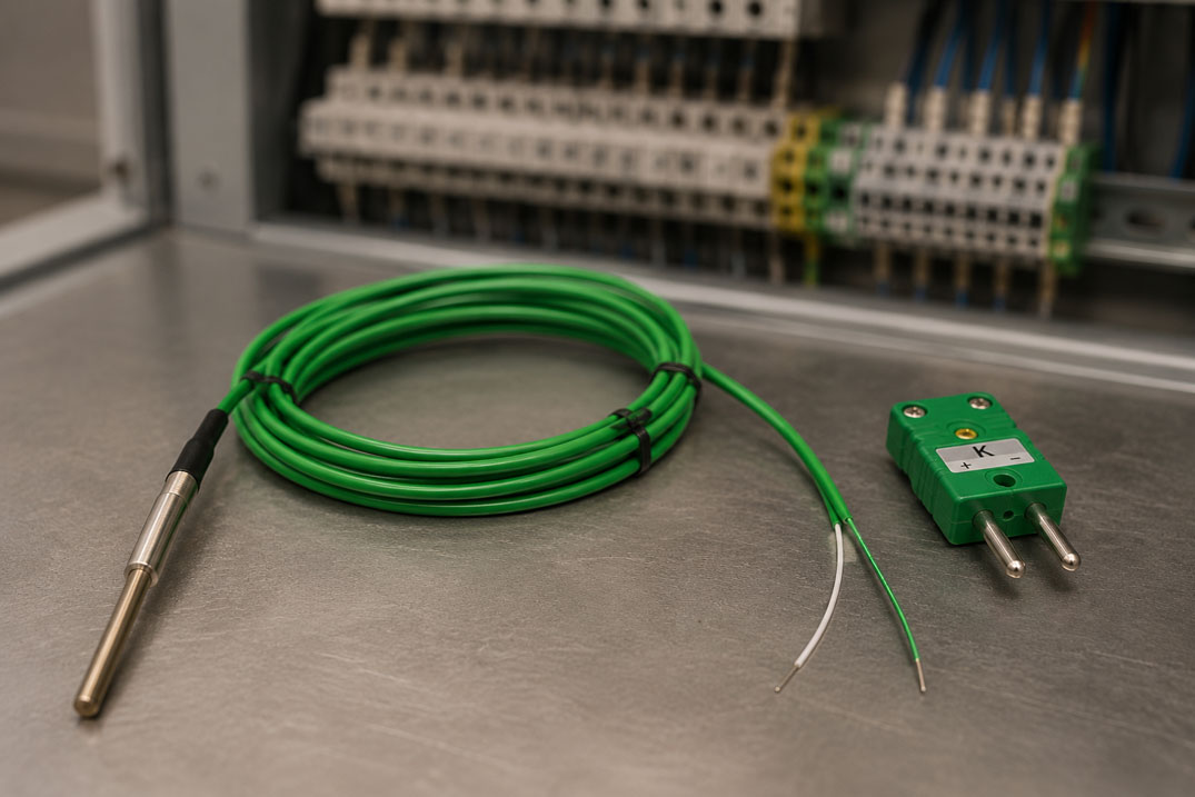
Thermocouples are often used in industrial plants where high temperatures, fast temperature changes or robust sensor designs are required. In practice, however, measurement errors repeatedly occur as soon as a thermocouple is extended or connected to a control system, display or transmitter.
A particularly common mistake is extending a thermocouple with normal copper cable. At first glance, this seems obvious: two wires are extended and connected to the evaluation unit. With thermocouples, however, temperature measurement works differently than with a Pt100. Therefore, an incorrect cable, incorrect polarity or unsuitable terminal point can lead to significantly incorrect measured values.
This article explains why thermocouples require special thermocouple cables or compensating cables, what role polarity plays and which connection errors occur particularly often in practice.
You can find an overview of suitable sensors in our category
Thermocouples.
Suitable transmitters and accessories can also be found in the category
Temperature transmitters and accessories for temperature sensors.
Table of contents
- Why is normal copper cable a problem with thermocouples?
- Basic principle: How does a thermocouple measure temperature?
- Thermocouple cable or compensating cable: What is the difference?
- Polarity with thermocouples: Why plus and minus are important
- Correctly executing terminal points, connectors and transitions
- Understanding cold junction compensation correctly
- Typical fault patterns and causes
- Connection examples: right and wrong
- When a thermocouple transmitter is useful
- Which thermocouples and transmitters are suitable?
- Practical examples from industrial plants
- Checklist for wiring
- Conclusion
- FAQ: Frequently asked questions about extending thermocouples
Why is normal copper cable a problem with thermocouples?
A thermocouple does not provide a resistance signal like a Pt100, but a very small thermoelectric voltage. This thermoelectric voltage is generated by the combination of two different metallic conductors and depends on the temperature difference between the measuring junction and the reference junction.
If a thermocouple is simply extended with normal copper cable, additional transitions between different materials are created. If these transitions are located at points with different temperatures or are not correctly taken into account by cold junction compensation, additional thermoelectric voltages are generated. The result is incorrect or unstable measured values.
- Wrong cable: Normal copper cable does not match the thermocouple type.
- Additional transitions: Every material combination can generate a thermoelectric voltage.
- Temperature differences at terminal points: Transitions at different temperatures cause measurement errors.
- Incorrect polarity: Swapped wires lead to incorrect temperature indication.
- Missing cold junction compensation: The evaluation unit must know where the transition to the reference junction is located.
Normal copper cable is therefore generally not suitable for directly extending a thermocouple signal. It can only be used sensibly after suitable signal conversion, for example after a transmitter with a 4 … 20 mA output.
Basic principle: How does a thermocouple measure temperature?
A thermocouple consists of two different metallic conductors. These are connected to each other at the measuring junction. When the measuring junction is heated or cooled, a temperature-dependent electrical voltage in the millivolt range is generated.
The evaluation unit measures this thermoelectric voltage and converts it into a temperature using the characteristic curve of the respective thermocouple type. The device must also take the temperature at the connection point into account. This correction is called cold junction compensation.
| Component | Task | Typical error |
|---|---|---|
| Measuring junction | This is where the process temperature is detected. | Sensor is positioned incorrectly or has poor thermal contact. |
| Thermocouple conductors | Generate the temperature-dependent thermoelectric voltage. | Wrong thermocouple type or wrong material. |
| Extension cable | Transmits the thermocouple signal to the evaluation unit. | Normal copper cable instead of thermocouple or compensating cable. |
| Terminal point | Connects sensor, cable and evaluation unit. | Wrong material, temperature gradient or swapped polarity. |
| Cold junction compensation | Corrects the temperature at the connection point. | Reference junction is not located where the device compensates. |
| Evaluation unit / transmitter | Converts thermoelectric voltage into temperature or standard signal. | Wrong thermocouple type or wrong measuring range set. |
The decisive point is: the thermocouple, extension, terminal points and evaluation unit together form one measuring system. If one part is executed incorrectly, the entire measured value can be wrong.
Thermocouple cable or compensating cable: What is the difference?
When extending thermocouples, a distinction is often made between thermocouple cable and compensating cable. Both are used to route the thermocouple signal to the display, PLC or transmitter. However, they are not identical.
| Cable type | Description | Typical use |
|---|---|---|
| Thermocouple cable | Consists of the same or very similar materials as the thermocouple. | For accurate extension of the thermocouple signal over longer distances. |
| Compensating cable | Consists of substitute materials with similar thermal behavior in the specified temperature range. | For defined temperature ranges and more cost-effective extensions. |
| Copper cable | Normal electrical cable without suitable thermoelectric properties. | Not suitable for directly extending a thermocouple signal. |
| Signal cable after transmitter | Transmits a converted signal, e.g. 4 … 20 mA. | After the transmitter, normal signal cable can be used. |
It is important that the thermocouple cable or compensating cable matches the thermocouple type used. A type K thermocouple requires a suitable type K thermocouple cable or a suitable type K compensating cable. The same applies to type J, type T, type N or other thermocouple types.
| Thermocouple type | Important when extending | Typical error |
|---|---|---|
| Type K | Use suitable type K thermocouple or compensating cable. | Extension with copper cable or incorrect polarity. |
| Type J | Cable must match the type J characteristic curve. | Confusion with type K or incorrect terminal connection. |
| Type T | Pay particular attention to correct material pairing. | Copper content leads to the false assumption that normal copper cable is suitable. |
| Type N | Suitable cable and evaluation for type N required. | Transmitter or display set to the wrong type. |
Polarity with thermocouples: Why plus and minus are important
Thermocouples have polarity. If the positive and negative wires are swapped, the sign of the thermoelectric voltage changes. In practice, this causes the temperature indication to react incorrectly or apparently decrease when heated.
A polarity error is particularly noticeable when the display moves in the wrong direction as the sensor is heated. Depending on the device and temperature range, the measured value can deviate significantly or appear completely implausible.
| Error | Effect | Check |
|---|---|---|
| Plus and minus swapped | Temperature moves in the wrong direction when heated. | Check polarity at sensor, connector, terminal and measuring device. |
| Color coding interpreted incorrectly | Wires are connected incorrectly at the evaluation unit. | Check standard, data sheet and cable type. |
| Connector wired incorrectly | Measured value jumps or is permanently incorrect. | Check thermocouple plug and socket for matching type. |
| Several terminal points swapped | Error is difficult to trace. | Trace wiring step by step from sensor to transmitter. |
Typical indications of incorrect polarity
- The measured value decreases although the sensor is being heated.
- The display reacts in the wrong direction.
- After an extension or repair, the measured value is suddenly implausible.
- The correct type is set on the transmitter, but the display remains incorrect.
- The error only occurs after a connector, terminal or extension.
Correctly executing terminal points, connectors and transitions
With thermocouples, terminal points and connectors are particularly critical. Every connection between different metals can generate an additional thermoelectric voltage. If both transitions are at the same temperature and are correctly compensated, this can be manageable. However, if temperature differences exist, measurement errors occur.
Terminal points in areas with strong temperature gradients are particularly problematic, for example near furnaces, heating tapes, machine housings, pipelines or poorly ventilated control cabinets.
| Connection point | Typical risk | Good practice |
|---|---|---|
| Connection head on sensor | Temperature at the connection head influences the reference junction. | Use suitable connection head position and suitable cable. |
| Terminal box | Different temperatures at terminals generate errors. | Keep terminals as evenly tempered and protected as possible. |
| Thermocouple connector | Wrong connector type or wrong material. | Select connector to match the thermocouple type. |
| Control cabinet terminal | Transition to copper before cold junction compensation. | Provide transition only at the measuring device or transmitter. |
| Repair point | Wrong wires or mechanically poor connection. | Connect thermocouple cable professionally and with matching type. |
With longer cable runs, the thermocouple signal should not be routed repeatedly through normal terminals, copper cables and intermediate connectors. A clean, continuous thermocouple or compensating cable to the point where cold junction compensation takes place is better.
Understanding cold junction compensation correctly
A thermocouple does not simply measure an absolute temperature at the tip. It provides a voltage that depends on the temperature difference between the measuring junction and the reference junction. In order for the evaluation unit to calculate the actual measuring junction temperature, the temperature at the reference junction must be taken into account.
This correction is called cold junction compensation. Depending on the design, it is located in the measuring device, in the temperature transmitter or in a separate reference junction. If the thermocouple is incorrectly transferred to copper beforehand, the actual reference junction may no longer be located where the device expects it to be.
| Situation | What happens? | Possible consequence |
|---|---|---|
| Thermocouple cable routed to transmitter | Cold junction compensation takes place at the transmitter. | Clean and common solution. |
| Thermocouple transferred to copper cable in the field | New transition point is created in the field. | Measurement error if this point is not compensated. |
| Terminal point is located in warm environment | Reference junction is not stable. | Measured value shifts with ambient temperature. |
| Transmitter installed in connection head | Thermocouple signal is converted directly at the sensor. | From there, a standard signal can be transmitted. |
| Standard signal 4 … 20 mA is transmitted | Thermoelectric voltage has already been evaluated. | Normal signal cable can be used. |
A sensible solution is often to place the transmitter as close as possible to the sensor or in the connection head. This means the sensitive thermocouple signal is only routed over a short distance. Afterwards, a more robust standard signal such as 4 … 20 mA can be transmitted to the PLC.
Typical fault patterns and causes
Many errors when extending thermocouples do not immediately appear as a complete failure. Often the measuring point continues to deliver values, but these are shifted, unstable or react implausibly to temperature changes.
| Fault pattern | Possible cause | Practical check |
|---|---|---|
| Measured value permanently too high or too low | Wrong compensating cable or incorrect cold junction compensation | Check cable type, terminal point and device setting. |
| Measured value decreases when heated | Polarity swapped | Check plus and minus over the entire connection path. |
| Measured value jumps or fluctuates | Loose terminal, broken cable or poor plug connection | Tighten terminals, move cable, check connector. |
| Measured value changes with control cabinet temperature | Transition to copper at the wrong point | Assess cold junction compensation and terminal point. |
| Display shows sensor break | Interruption in sensor or cable | Check continuity and cable to the measuring point. |
| Value is wrong after extension | Copper cable, wrong type or incorrect polarity used | Compare extension cable and wiring diagram. |
| Measured value drifts over the long term | Sensor ageing, unsuitable cable or thermal stress | Check sensor, cable and operating temperature. |
Connection examples: right and wrong
When extending a thermocouple, the entire connection path matters. The following examples show typical correct and incorrect wiring arrangements.
| Setup | Assessment | Why? |
|---|---|---|
| Type K thermocouple → suitable type K compensating cable → type K transmitter | Correct | Cable, sensor and evaluation match. |
| Type K thermocouple → copper cable → measuring device with cold junction compensation at the device | Incorrect | Transition to copper is before the compensated reference junction. |
| Type J thermocouple → type K compensating cable → type J display | Incorrect | Cable type does not match the thermocouple characteristic curve. |
| Thermocouple → transmitter in connection head → 4 … 20 mA to PLC | Correct | Thermoelectric voltage is converted early; normal signal cable is then possible. |
| Thermocouple → suitable thermocouple cable → thermocouple connector of the same type → display | Correct | Material pairing and connection path remain suitable. |
| Thermocouple → screw terminal in warm machine room → copper cable to PLC | Incorrect | Uncontrolled reference junction and temperature gradient cause measurement errors. |
The safest approach is to always consider the sensor, cable, connector and evaluation unit as one complete measuring system. The thermocouple type must be clearly continuous from the sensor to the cold junction compensation.
When a thermocouple transmitter is useful
A thermocouple transmitter converts the sensitive millivolt signal of the thermocouple into a more robust standard signal, for example 4 … 20 mA. This is particularly useful when longer distances to the PLC must be bridged or when electrical interference is to be expected.
The transmitter should be installed at a suitable location if possible, for example in the connection head, in the field housing or in the control cabinet. It is important that the thermocouple signal is correctly routed up to the cold junction compensation.
| Situation | Why transmitter useful? | Advantage |
|---|---|---|
| Long cable to PLC | Thermoelectric voltage is sensitive to connection errors and interference. | 4 … 20 mA signal is more robust over longer distances. |
| Many terminal points in the control cabinet | Several transitions can generate thermoelectric voltages. | Early signal conversion reduces error sources. |
| Interference-prone industrial environment | Motors, frequency converters or power cables can influence measuring signals. | Electrical isolation and standard signal improve measurement reliability. |
| PLC has no thermocouple input | Direct connection is not possible. | Transmitter provides a standardized input signal. |
| Parameterization and diagnostics desired | Measuring range and sensor type should be flexibly adjustable. | Digital transmitters simplify commissioning and service. |
For thermocouples, for example, the
Thermocouple transmitter DT 45800
can be used. For more universal applications with Pt, Ni, KTY, TC, resistance, potentiometer or mV signals, the
Temperature transmitter DT 45000
can be a suitable solution.
Which thermocouples and transmitters are suitable?
The right selection depends on whether the measuring point is to be implemented directly in the process, in a thermowell, on a machine, in the plastics industry or as a cable thermocouple. In addition, it must be decided whether the thermocouple signal is evaluated directly or converted into a standard signal via a transmitter.
| Product | Especially relevant for | Note |
|---|---|---|
| WIKA Type TC40 cable thermocouple | Flexible temperature measuring points with connection cable | Relevant when a compact thermocouple solution with suitable cable is required. |
| WIKA Type TC10-C screw-in thermocouple | Direct process connections on vessels, pipelines or plant components | Suitable when a thermocouple with process connection and thermowell is required. |
| WIKA Type TC10-A measuring insert for thermocouple | Replaceable measuring inserts for thermocouples | Useful when measuring inserts are installed in existing assemblies or thermowells. |
| Type TC47-MB screw-in melt thermocouple | Plastics industry and special applications on extrusion machines | Relevant for temperature measurements on machine components and melt applications. |
| Thermocouple transmitter DT 45800 | Conversion of thermocouple signals into standard signals | Suitable when TC signals need to be electrically isolated and processed robustly. |
| Temperature transmitter DT 45000 | Universal temperature and mV signal acquisition | Useful when different sensor signals need to be flexibly converted into standard signals. |
| WIKA Type T16 digital temperature transmitter | Thermocouple connection in head-mounted or rail-mounted version | Interesting when a temperature transmitter specifically for thermocouples is required. |
You can find a complete overview in the category
Thermocouples
as well as in the category
Temperature transmitters and accessories for temperature sensors.
Practical examples from industrial plants
Example 1: Type K thermocouple extended with copper cable
A type K thermocouple is extended in a plant with normal copper cable up to the control cabinet. After the extension, the control system displays significantly deviating temperatures. The cause is the transition from thermocouple material to copper at an uncompensated terminal point. The solution is a suitable type K thermocouple or compensating cable up to the cold junction compensation.
Example 2: Display falls when heated
After replacing a sensor, the display decreases although the measuring point is being heated. In this case, the polarity is often swapped. Positive and negative wires must be checked at the thermocouple, extension cable, connector and measuring device.
Example 3: Measured value fluctuates with control cabinet temperature
A thermocouple is transferred to copper cable in the field and the cable continues into the control cabinet. The measured value changes with the ambient temperature at the terminal point. However, cold junction compensation only takes place at the evaluation unit. As a result, the temperature is compensated at the wrong point.
Example 4: Type K sensor on type J input
A type K thermocouple is connected to a transmitter that is accidentally set to type J. The display does provide values, but they are incorrect. Sensor type, cable type and transmitter parameterization must always match.
Example 5: Long cable near frequency converters
A thermocouple signal is routed over a long cable near motor cables and frequency converters. The measured value jumps or fluctuates. In addition to the correct thermocouple or compensating cable, shielding, cable routing and a transmitter close to the sensor can help stabilize the measurement.
Checklist for wiring
This checklist can be used to systematically check thermocouple wiring before commissioning or during troubleshooting.
| Check question | Why important? | Assessment |
|---|---|---|
| Which thermocouple type is installed? | Type K, J, T, N or other types have different characteristic curves. | Check nameplate, data sheet or order code. |
| Does the extension cable match the thermocouple type? | Wrong cable causes measurement errors. | Use thermocouple or compensating cable suitable for the sensor type. |
| Was normal copper cable used directly? | Copper cable is usually unsuitable before cold junction compensation. | Replace with suitable thermocouple or compensating cable. |
| Is the polarity correct? | Swapped wires lead to incorrect temperature response. | Check plus and minus at sensor, cable, connector and device. |
| Is cold junction compensation located at the correct point? | Wrong reference junction shifts the measured value. | Trace setup from sensor to evaluation unit. |
| Are terminal points evenly tempered? | Temperature gradients at transitions generate errors. | Position terminal points protected and appropriately. |
| Is the evaluation unit parameterized correctly? | Thermocouple type and measuring range must be correct. | Compare parameterization with sensor and cable. |
| Is the cable protected against interference? | Millivolt signals are sensitive. | Check shielding, cable routing and distance from power cables. |
| Would a transmitter close to the sensor be useful? | Standard signals are more robust over longer distances. | Check 4 … 20 mA conversion or field transmitter. |
Conclusion: Only extend thermocouples with suitable cable
A thermocouple must not be treated like a simple electrical contact. Temperature measurement is based on a very small thermoelectric voltage and on the material combination of the conductors used. Therefore, extension with normal copper cable can lead to significant measurement errors.
For reliable measurement, thermocouple type, thermocouple cable or compensating cable, polarity, connectors, terminal points, cold junction compensation and evaluation unit must match. Especially with longer cable runs or interference-prone industrial environments, a thermocouple transmitter close to the sensor can significantly improve measurement reliability.
You can find a suitable preselection in the categories
Thermocouples
and
Temperature transmitters and accessories for temperature sensors.
FAQ: Frequently asked questions about extending thermocouples
Can a thermocouple be extended?
Yes, a thermocouple can be extended. However, a suitable thermocouple cable or compensating cable should be used that matches the respective thermocouple type. Normal copper cable is generally not suitable for direct extension.
Why should a thermocouple not simply be extended with copper cable?
The transition from thermocouple material to copper creates additional reference junctions. If these are not correctly compensated or have different temperatures, measurement errors occur. Therefore, the thermocouple signal must be routed suitably up to the cold junction compensation.
What is a compensating cable for a thermocouple?
A compensating cable is a special cable whose thermoelectric properties match the thermocouple type in the specified temperature range. It is used to correctly route the thermocouple signal to the measuring device or transmitter.
What is the difference between thermocouple cable and compensating cable?
A thermocouple cable consists of the same or very similar materials as the thermocouple. A compensating cable consists of substitute materials with similar thermal behavior in the specified temperature range. Both must match the thermocouple type.
What happens if the polarity of the thermocouple is incorrect?
If plus and minus are swapped, the display reacts incorrectly. Often the measured value falls when heated or shows implausible temperatures. Polarity must therefore be consistently correct from the sensor to the evaluation unit.
What does cold junction compensation mean?
Cold junction compensation takes into account the temperature at the reference junction, i.e. the point where the thermocouple signal is evaluated or transitions to another material. Without correct cold junction compensation, the temperature measurement is faulty.
Do I need special thermocouple connectors?
Yes, connectors should match the thermocouple type. Incorrect connectors or unsuitable materials can cause additional thermoelectric voltages and thus measurement errors.
When should a thermocouple transmitter be used?
A transmitter is useful if the sensitive thermocouple signal is to be transmitted over longer distances, if interference is to be expected or if the PLC requires a standard signal such as 4 … 20 mA. Examples are the
Thermocouple transmitter DT 45800
or the
Temperature transmitter DT 45000.
What happens if thermocouple type and transmitter do not match?
If, for example, a type K thermocouple is evaluated on a type J input, the device calculates with the wrong characteristic curve. This results in incorrect measured values. Sensor type, cable and parameterization must always match.
Where can I find suitable thermocouples and transmitters?
You can find an overview in the categories
Thermocouples
and
Temperature transmitters and accessories for temperature sensors.