


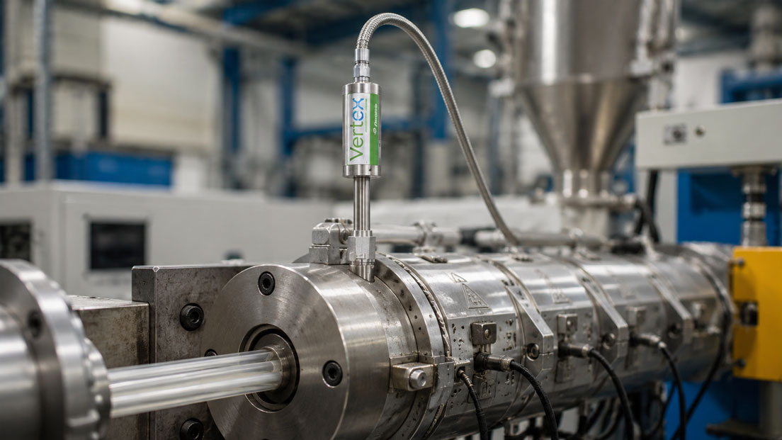
In melt pressure sensors and melt pressure transducers, the diaphragm is positioned directly at one of the most critical points of the process: it separates the hot plastic melt, polymer or other process medium from the internal measuring system and at the same time transmits the pressure to the measuring cell. If the diaphragm does not match the medium, temperature, abrasion or chemical load, measurement errors, drift, damage or premature sensor failure can occur.
Especially in plastics processing, the diaphragm is often subjected to heavy stress. Polymers can contain fillers, glass fibers, mineral components, additives, flame retardants, color masterbatches or abrasive recycled content. In addition, high temperatures, high pressures, pressure spikes, cleaning processes and mechanical loads during installation also act on the sensor. It is therefore not sufficient to select a melt pressure sensor only according to pressure range, output signal and insertion length.
This article explains why diaphragm material is so decisive in melt pressure sensors. The focus is on standard diaphragms, DyMax®-coated stainless steel, Inconel, Hastelloy, titanium nitride or TiAlN coatings, abrasive polymers, elastomers, fillers, glass fibers, corrosion, cleaning, service life, typical damage patterns and correct selection based on medium, process and application.
Table of contents
- Basics: what is the function of the diaphragm in a melt pressure sensor?
- Process loads: temperature, pressure, abrasion and chemistry
- Standard diaphragm: when a classic version is sufficient
- Coatings: DyMax®, TiN, TiAlN and abrasive applications
- Diaphragm materials: stainless steel, Inconel, Hastelloy and special materials
- Assessing polymers, elastomers and fillers correctly
- Abrasion: why glass fibers, minerals and recycled material are critical
- Corrosion and chemical stress on the diaphragm
- Cleaning, deposits and product changes
- Installation and mounting: avoiding diaphragm damage
- Measurement stability, output signal and troubleshooting
- Typical diaphragm damage and possible causes
- Practical example: abrasive polymer with glass fiber content
- Which measuring instruments / products are suitable?
- Conclusion: always derive diaphragm material from medium and process
- FAQ: frequently asked questions about diaphragm material in melt pressure sensors
Basics: what is the function of the diaphragm in a melt pressure sensor?
The diaphragm of a melt pressure sensor is the wetted component that absorbs the process pressure. It is located at the front end of the sensor and comes into direct contact with the plastic melt, polymer or respective process medium. The pressure causes minimal deformation of the diaphragm. This deformation is converted into an electrical signal via the internal transmission system and measuring cell.
The diaphragm must meet two requirements at the same time. It must be sensitive enough to transmit the process pressure precisely, and robust enough to withstand temperature, pressure, mechanical stress and the medium. This exact conflict of objectives makes the selection of the diaphragm material so important. A very sensitive diaphragm can be damaged more quickly in abrasive media, while a more robust version may need to be designed differently for certain measuring ranges or applications.
In practice, the diaphragm is often only considered once a sensor fails. Typical signs include drift, unstable measured values, zero point shift, implausible pressure indication or visible damage to the diaphragm. Such errors can be caused by incorrect material selection, unsuitable coating, abrasive media, corrosion, improper cleaning or incorrect installation.
The diaphragm should therefore already be considered during sensor selection. The decisive question is not only whether the sensor mechanically fits into the bore, but whether its wetted design matches the actual melt, additives, temperature, cleaning process and required service life.
| Function of the diaphragm | Meaning for measurement | Practical consequence |
|---|---|---|
| Pressure pickup | Diaphragm transmits process pressure to the measuring system | Damage directly leads to measurement errors or failure. |
| Media separation | Protects the internal sensor system from the melt | Material must be chemically and thermally suitable. |
| Contact surface to the polymer | Medium can adhere, rub or chemically attack | Coating and surface must match the application. |
| Mechanical element | Deforms in a controlled way under pressure | Installation errors or pressure spikes can be critical. |
| Long-term stability | Influences drift and repeatability | Material selection affects service life and maintenance. |
Process loads: temperature, pressure, abrasion and chemistry
Melt pressure sensors often operate in very demanding process environments. In extrusion lines, injection molding machines, compounding systems or recycling processes, high temperatures and pressures occur. At the same time, the medium may be highly viscous, contain fillers or act differently on the diaphragm during start-up and cooling.
The load on the diaphragm is therefore not only a question of maximum pressure. Pressure spikes, pulsations, local temperature differences, vibrations, shear forces, deposits and cleaning processes also influence service life. A sensor may generally be suitable for the pressure range, but still wear prematurely due to abrasive fillers or a corrosive polymer mixture.
Applications with glass fiber reinforced plastics, mineral fillers, ceramic additives, recycled material, carbon black, flame retardants or highly filled compounds are particularly critical. These components can act on the diaphragm like an abrasive medium. Depending on flow, installation position and process control, the diaphragm is continuously subjected to mechanical stress.
Chemical influences must also not be underestimated. Fluoropolymers, aggressive additives, decomposition products, cleaning media or thermally decomposed polymers can attack certain materials. The selection of the diaphragm material should therefore always consider medium, temperature, additives, fillers and process states together.
| Load | Typical cause | Effect on the diaphragm |
|---|---|---|
| Temperature | Hot plastic melt, heating and cooling phases | Thermal stress, drift, material aging. |
| Pressure | Extrusion, injection molding, start-up, clogging | Mechanical deformation or overload. |
| Abrasion | Glass fibers, fillers, recycled material, minerals | Material removal, scratches, diaphragm wear. |
| Corrosion | Additives, fluoropolymers, aggressive decomposition products | Chemical attack, pitting, material weakening. |
| Deposits | Sticky polymers, elastomers, unsuitable surface | Measured value distortion, cleaning damage, diaphragm deformation. |
Standard diaphragm: when a classic version is sufficient
A standard diaphragm can be sufficient in many classic plastics applications if the medium is relatively homogeneous, not highly abrasive and chemically uncritical. Typical examples include standard polymers without high filler content, clean production conditions and processes in which no unusual cleaning or corrosion loads occur.
The advantage of a standard version often lies in availability, cost-effectiveness and proven use. For many standard extrusion processes, a classic diaphragm design is technically sensible as long as pressure range, temperature, insertion length, thread, signal and medium match. Nevertheless, even here, the polymer name alone should not be considered. A polyamide without glass fiber content must be assessed differently from a glass fiber reinforced polyamide. A standard polypropylene without aggressive additives is different from a highly filled or recycled material.
A standard diaphragm becomes problematic when abrasion, adhesion or chemical attack increase. Scratches, material removal, damage or drift can then develop more quickly. Frequent product changes and cleaning processes can also make a different diaphragm design useful.
In practice, the question should therefore not be whether a standard diaphragm is fundamentally good or bad. The decisive point is whether it matches the specific application. For simple, known media, it can be the right choice. For abrasive, sticky or chemically demanding media, a coated or alternative diaphragm should be checked.
Coatings: DyMax®, TiN, TiAlN and abrasive applications
Coatings are used to make the diaphragm more resistant to certain loads. Depending on the application, the focus may be on abrasion resistance, corrosion resistance, reduced adhesion or a combination of these properties. In melt pressure sensors, coatings are therefore an important selection point when the standard diaphragm is unlikely to be sufficient.
DyMax®-coated wetted parts are used in various Dynisco melt pressure sensors. Such coatings are particularly interesting when abrasion resistance and durability in more demanding plastics processes need to be improved. In sensors such as the Vertex sensor, for example, a robust Inconel diaphragm with DyMax® coating is described, which can be relevant for applications with higher mechanical and chemical stress.
Titanium nitride or TiAlN coatings can also play a role when adhesion, abrasion or certain polymer conditions are critical. However, the suitable coating depends strongly on the medium. A coating that works very well with one polymer is not automatically the best solution for another medium. Temperature, cleaning method and process control also influence suitability.
Important: a coating is not universal protection against all damage. It can significantly improve service life if it is correctly matched to the application. However, if the cause is incorrect installation, excessive pressure, incorrect bore, mechanical collision or unsuitable cleaning, even a high-quality coating only provides limited protection.
| Version / coating | Typical benefit | Important to check |
|---|---|---|
| Standard diaphragm | Proven solution for many standard polymers | Check abrasion, additives and cleaning conditions. |
| DyMax® coating | Increased resistance in demanding applications | Compare suitability for medium, temperature and fillers. |
| TiN / TiAlN coating | Can be advantageous for adhesion and abrasion | Assess polymer, cleaning method and process conditions. |
| Armoloy coating | Can improve abrasion resistance and thread behavior | Check compatibility with medium and installation situation. |
| Special coating | Adaptation to critical media or special processes | Select only after concrete application assessment. |
Diaphragm materials: stainless steel, Inconel, Hastelloy and special materials
In addition to the coating, the base material of the diaphragm is decisive. Stainless steel is used in many standard applications and is suitable for numerous polymers. However, for higher chemical or mechanical requirements, materials such as Inconel, Hastelloy or other special materials may become necessary.
Inconel often becomes interesting where high temperatures, mechanical stress or more demanding media occur. In certain sensor series, Inconel 718 is used as diaphragm material, sometimes in combination with a DyMax® coating. This combination can offer higher robustness in demanding applications than simple standard versions.
Hastelloy may become relevant for chemically more critical media, for example when certain polymers, additives or decomposition products create a stronger corrosion load. However, selection should never be made as a blanket decision. The actual medium, temperature and concentrations or cleaning substances are decisive.
For special materials, the basic rule is: the operator or user must provide the most accurate information possible about the medium. Manufacturer data, experience from similar processes and material approvals should be considered together. Without precise information on polymer, additives, fillers, temperature and cleaning, no reliable selection of the diaphragm material is possible.
| Diaphragm material | Typical application idea | Limit / check point |
|---|---|---|
| Stainless steel | Standard applications with less critical media | Not automatically suitable for corrosion or strong abrasion. |
| Inconel | More demanding thermal and mechanical conditions | Medium and coating still need to be checked separately. |
| Hastelloy | Chemically more critical applications | Assess concrete media resistance based on process data. |
| Coated stainless steel | Improved abrasion or surface properties | Coating must match melt and cleaning. |
| Special material | Special media or extreme process conditions | Project-specific clarification with manufacturer and operator required. |
Assessing polymers, elastomers and fillers correctly
The statement “plastic melt” is not sufficient for selecting the diaphragm material. The decisive factor is which polymer is processed and which components it contains. Polyethylene, polypropylene, polyamide, polycarbonate, PET, PVC, PEEK, PTFE, elastomers or engineering compounds behave differently. Additives, fillers and processing temperatures additionally change the load.
Elastomers and sticky media can adhere to the diaphragm and thereby influence measured values or cause cleaning problems. Some materials tend to stick to certain surfaces. As a result, the diaphragm can no longer react freely or is mechanically stressed during cleaning attempts.
Filled polymers often represent a significantly higher load. Glass fibers, carbon fibers, mineral fillers, talc, chalk, ceramic particles or metal powder can act abrasively. The higher the filler content and the more unfavorable the flow at the sensor, the more strongly the diaphragm can wear.
Recycled material also deserves special attention. Recyclates can contain fluctuating compositions, foreign particles, contamination or unexpected filler contents. A sensor that works reliably with virgin material can be subjected to higher stress with recycled material. Material changes and recipe changes should therefore always be included in sensor selection.
Abrasion: why glass fibers, minerals and recycled material are critical
Abrasion is one of the most important reasons for using special diaphragm materials or coatings. It occurs when hard particles or fillers flow past the diaphragm and mechanically stress its surface. At high pressures, high viscosity and unfavorable flow conditions, this effect can increase significantly.
Glass fiber reinforced plastics are a typical example. The glass fibers can attack the diaphragm surface over a long period of time. Mineral fillers such as talc, chalk or other hard particles can also act abrasively. This load is particularly relevant in compounding systems, recycling processes and engineering plastics.
The consequences often appear gradually. Initially, the sensor may still measure stably; later, drift, noisy signals or changed response behavior occur. Visible inspection may reveal scratches, dull areas, material removal or mechanical damage. If the diaphragm is severely weakened, the sensor can fail permanently.
For abrasive applications, it should therefore be checked early whether a coated diaphragm or a more robust diaphragm material is required. At the same time, the installation situation must be considered. If the diaphragm protrudes unfavorably directly into a heavily loaded flow zone or the bore is incorrectly executed, abrasion can be additionally intensified.
| Abrasion source | Typical application | Selection note |
|---|---|---|
| Glass fibers | Engineering plastics, PA-GF, PBT-GF, PP-GF | Check coated or more robust diaphragm. |
| Mineral fillers | Talc, chalk, ceramic additives | Assess abrasion resistance and flow at the measuring point. |
| Recycled material | Regranulate, mixed material, contaminated batches | Consider fluctuating composition and foreign particles. |
| Color masterbatch | Pigments and additive concentrates | Check adhesion, abrasion and cleaning. |
| Highly filled compounds | Automotive, electrical, engineering applications | Select sensor not only according to polymer base, but according to recipe. |
Corrosion and chemical stress on the diaphragm
In addition to mechanical wear, chemical attack can damage the diaphragm. Corrosion does not only occur through classic liquids or acids, but can also be relevant in plastics processes. Certain polymers, additives, flame retardants, halogen-containing materials, fluoropolymers or decomposition products can attack the wetted parts.
PTFE and other fluoropolymers are examples of applications where material selection must be carried out particularly carefully. Depending on the process conditions, corrosive properties or decomposition products may become relevant. In such cases, alternative materials such as Hastelloy or Inconel are often checked.
Temperature also plays an important role. A medium can be uncritical at moderate temperature, but become significantly more aggressive at higher processing temperature. Thermal decomposition, longer residence times, oxygen ingress or cleaning processes can increase chemical stress.
For selecting the diaphragm material, this means: chemical resistance must be assessed based on the specific process data. This includes polymer, additives, fillers, processing temperature, residence time, cleaning chemistry and possible decomposition conditions. Without this information, no reliable statement on media compatibility should be made.
Cleaning, deposits and product changes
Cleaning processes can place heavy stress on the diaphragm. Mechanical scraping, unsuitable tools, aggressive cleaning chemicals or thermal changes can cause damage. Trying to remove adhering material directly from the diaphragm is particularly dangerous. The diaphragm is a sensitive measuring component and must not be treated like a robust metal surface.
Deposits often occur with sticky polymers, elastomers, color changes, temperature deviations or longer downtimes. If material remains on the diaphragm, it can influence pressure transmission. During restart, solid residues can also create mechanical loads.
Product changes are also relevant. Different materials can adhere differently, be differently abrasive or require different cleaning temperatures. If a line frequently switches between materials, the diaphragm material should be assessed not only for the main product, but for all relevant media and cleaning states.
In practice, gentle cleaning is decisive. If sensors must be regularly removed or cleaned, mounting bore, installation position, tool access and cleaning method should be considered from the beginning. An incorrect cleaning strategy can quickly damage an otherwise suitable diaphragm.
Installation and mounting: avoiding diaphragm damage
Many types of damage to melt pressure sensors are not caused by the medium, but by installation errors. The diaphragm is located at the sensitive front end of the sensor. If the mounting bore is too short, too narrow, dirty, damaged or not correctly executed, the diaphragm can be mechanically stressed or directly damaged.
Incorrect bore depth or an unsuitable seat is particularly critical. If the sensor does not seat correctly or protrudes too far into the process, the diaphragm can come into contact with solid components, tools or material accumulations. Excessive tightening torque can also mechanically stress the sensor.
Before installation, the bore should be clean, dimensionally correct and free of solidified material. The sensor should be installed with suitable tools and according to the manufacturer’s specifications. If an old sensor has been damaged, a new sensor should not simply be screwed in without checking the bore and installation situation. Otherwise, the new sensor may suffer the same damage.
Caution is also required during removal. If plastic has solidified, the sensor can be damaged when unscrewed. In many applications, the plant must be brought to a suitable temperature before the sensor is removed. Installation and removal should therefore be considered part of the sensor’s service life.
| Mounting point | Possible error | Effect |
|---|---|---|
| Bore depth | Sensor sits too deep or too shallow | Diaphragm stress, incorrect pressure contact, damage. |
| Thread / seating surface | Dirty, damaged or not dimensionally correct | Leakage, incorrect seating, mechanical stress. |
| Tightening torque | Too high or uneven | Mechanical stress on the sensor. |
| Solidified material | Sensor is removed cold | Diaphragm or stem can be damaged. |
| Cleaning the bore | Residues remain in the installation space | New sensor can be damaged again immediately. |
Measurement stability, output signal and troubleshooting
Diaphragm damage does not always immediately appear as complete failure. The problem often starts with zero point shift, unstable measured values, slow response behavior or drift. Such symptoms can come from the diaphragm, but can also be caused by signal wiring, evaluation device, temperature drift, incorrect parameterization or process instability.
For this reason, the entire measuring chain should be considered during troubleshooting. The sensor itself, diaphragm, installation, medium, temperature, output signal and evaluation must be checked together. Especially with transmitters with 4–20 mA output, the sensor may be mechanically intact, while scaling, supply, load or signal cable cause problems.
The UPS4E loop calibrator is helpful for testing 4–20 mA signals. It can be used to measure or simulate current loops and detect scaling errors between melt pressure transmitter, display, PLC and control system. This makes it easier to distinguish whether the problem is in the electrical measuring chain or in the mechanically stressed diaphragm.
With mV/V sensors, excitation, shunt calibration, bridge signal, display instrument and cable routing must also be checked. A damaged sensor element, deformed diaphragm or error in the evaluation can produce similar symptoms. Systematic testing reduces unnecessary sensor replacement and helps identify the actual cause.
Typical diaphragm damage and possible causes
The diaphragm can be damaged in different ways. Abrasion often leads to visible surface wear, scratches or a dull surface. Depending on the medium, corrosion appears as discoloration, pitting or material attack. Mechanical damage is often caused by incorrect installation, tool contact, solidified material or improper cleaning.
A deformed diaphragm is particularly critical. It can be caused by overpressure, pressure spikes, incorrect bore, mechanical contact or deposits. If the diaphragm is permanently deformed, the zero point shifts or the sensor no longer measures correctly. In many cases, such a sensor can no longer be used reliably.
Deposits can also act like damage, even if the diaphragm itself is not initially destroyed. If material sticks to the diaphragm or hardens, pressure transmission is changed. If this deposit is removed with an unsuitable tool, it often results in actual diaphragm damage.
The process should therefore always be considered during root cause analysis. A single defective sensor is not only a spare part issue. It can be an indication of incorrect material selection, changed recipe, increased filler content, incorrect cleaning, unfavorable installation or process disturbances.
| Damage pattern | Possible cause | Test approach |
|---|---|---|
| Scratched diaphragm | Abrasive fillers or mechanical cleaning | Check fillers, coating and cleaning method. |
| Deformed diaphragm | Overpressure, installation error, solidified material | Check pressure spikes, bore and installation. |
| Corrosion / pitting | Chemically unsuitable material | Compare polymer, additives, temperature and material. |
| Deposits | Sticky polymers, incorrect temperature, product changes | Assess surface, coating and process control. |
| Drift / unstable measured value | Diaphragm damage, temperature, signal error or process instability | Check sensor, installation, signal path and process together. |
Practical example: abrasive polymer with glass fiber content
In an extrusion line, an engineering plastic with a high glass fiber content is processed. The installed melt pressure sensor has a standard diaphragm. After an initially stable operating phase, measured value fluctuations increasingly occur. Later, the zero point shifts, and inspection shows visible wear marks on the diaphragm.
The analysis shows that the process is no longer operated with the originally assumed standard polymer. The glass fiber content was increased, and color masterbatches are also used. As a result, the diaphragm was exposed to a higher abrasive load than expected. In addition, the measuring point is located in an area with unfavorable flow, causing particles to pass the diaphragm with high stress.
For the replacement measuring point, medium, filler content, temperature, pressure range, installation position and cleaning process are reassessed. It is checked whether a DyMax®-coated version, a more robust Inconel diaphragm or another coated diaphragm design better suits the application. In addition, the mounting bore is checked so that the new sensor is not damaged by a mechanical fault.
The example shows: the correct diaphragm selection depends not only on the base polymer. Fillers, recipe changes, installation position and cleaning can significantly influence the sensor’s service life.
Which measuring instruments / products are suitable?
The ICS page selection of the right diaphragm material for melt pressure sensors and melt pressure transmitters is a useful starting point when the diaphragm is to be assessed specifically according to medium, polymer, abrasion or corrosion risk. It helps to view selection not only via pressure range, but via the wetted design.
The category Dynisco melt pressure sensors includes various sensor series for melt pressure measurements in extrusion, injection molding, compounding and plastics processing. Depending on the series, different pressure ranges, accuracies, diaphragm designs, coatings and designs are available.
For applications with increased requirements for signal transmission and industrial integration, the category Dynisco melt pressure transmitters is also relevant. Transmitters with amplified output signal can be particularly useful when measured values are to be transmitted directly to PLCs, controllers or control systems.
The Vertex sensor is particularly interesting when a robust fill-free version with Inconel 718 diaphragm with DyMax® coating is required. Such versions can play an important role in demanding applications with abrasion, corrosion or sustainability requirements.
If melt pressure transmitters with 4–20 mA output are integrated into a control system, the UPS4E loop calibrator is a helpful test tool. It can be used to check whether transmitter, display, PLC and control system use the same scaling and whether the electrical measuring chain is working correctly.
| Product / area | Typical use | Particularly relevant for |
|---|---|---|
| Selection of the right diaphragm material | Guidance for diaphragm selection | Polymer, abrasion, corrosion, coating and material selection |
| Dynisco melt pressure sensors | Melt pressure measurement with mV/V signal | Extrusion, injection molding, compounding and plastics processing |
| Dynisco melt pressure transmitters | Melt pressure measurement with amplified output signal | PLC connection, controllers, control systems and industrial process monitoring |
| Vertex sensor | Robust fill-free melt pressure transmitter | Demanding applications, DyMax® coating, Inconel diaphragm and HART communication |
| UPS4E loop calibrator | Testing and simulation of 4–20 mA signals | Commissioning, scaling check, troubleshooting and signal comparison |
Conclusion: always derive diaphragm material from medium and process
The diaphragm material in melt pressure sensors is not a minor detail, but a decisive factor for service life, measurement stability and operational safety. The diaphragm is directly in the process and must withstand pressure, temperature, abrasion, adhesion, cleaning and chemical stress. Incorrect selection can lead to drift, damage or premature failure.
Especially with abrasive polymers, glass fiber reinforced plastics, filled compounds, elastomers, fluoropolymers, recycled material or frequent product changes, the diaphragm design should be checked specifically. Standard diaphragm, coated diaphragm, DyMax® coating, Inconel, Hastelloy or other special versions must be assessed based on the specific application.
The most important recommendation is: do not select diaphragm material as a blanket rule, but always derive it from medium, additives, fillers, temperature, pressure range, installation situation and cleaning. In addition, mounting bore, installation and signal path should be checked, because many sensor failures are caused not only by the medium, but by the interaction of process, mechanics and measuring chain.
FAQ: frequently asked questions about diaphragm material in melt pressure sensors
Why is the diaphragm so important in melt pressure sensors?
The diaphragm is the wetted component that absorbs the process pressure. If it is damaged, worn or chemically attacked, this directly affects the measurement.
What happens if the wrong diaphragm material is selected?
Drift, unstable measured values, corrosion, abrasion, deposits, diaphragm deformation or complete sensor failure can occur.
Is a standard diaphragm sufficient for all plastic melts?
No. A standard diaphragm can be sufficient for many simple applications, but it is not automatically suitable for abrasive, sticky or corrosive media.
When is a coated diaphragm useful?
A coated diaphragm is useful when abrasion, adhesion or chemical stress would place too much load on the standard diaphragm.
What is DyMax® in melt pressure sensors?
DyMax® is a coating used for wetted parts in certain Dynisco sensors. It can improve resistance to abrasion and corrosion in demanding applications.
When is Inconel interesting as a diaphragm material?
Inconel can be interesting under higher thermal or mechanical requirements, especially when an additional suitable coating is used.
When should Hastelloy be checked?
Hastelloy may become relevant for chemically more critical media. Suitability must always be checked based on medium, temperature, additives and process data.
Why are glass fiber reinforced plastics critical?
Glass fibers act abrasively and can mechanically attack the diaphragm surface over a longer period of time. This can cause the diaphragm to wear or become damaged.
Are recycled materials more problematic for the diaphragm?
Recycled materials can contain fluctuating compositions, foreign particles or abrasive components. This can expose the diaphragm to greater stress than defined virgin material.
What role do elastomers play?
Elastomers or sticky media can adhere to the diaphragm and influence pressure transmission. Cleaning can also become more difficult.
Can corrosion also occur with plastic melts?
Yes. Certain polymers, additives, flame retardants, fluoropolymers or decomposition products can chemically attack wetted materials.
Why does PTFE require special attention in material selection?
Fluoropolymers such as PTFE can generate corrosive properties or critical decomposition products depending on process conditions. Material selection should therefore be checked carefully.
Can a coating prevent all diaphragm damage?
No. A coating can improve service life, but it does not reliably protect against incorrect installation, mechanical collision, incorrect bore or unsuitable cleaning.
What typical damage can be seen on diaphragms?
Typical damage includes scratches, abrasion, deformation, corrosion, deposits, pitting or visible mechanical damage.
Why is the mounting bore so important?
An incorrect, dirty or damaged mounting bore can mechanically stress or directly damage the diaphragm. The bore must therefore be checked before sensor installation.
Can a sensor be damaged by cleaning?
Yes. Mechanical scraping, unsuitable tools or aggressive cleaning conditions can damage the diaphragm. Cleaning must match the diaphragm and the medium.
How can you tell whether an error comes from the diaphragm or from the signal?
Sensor, diaphragm, installation, process and electrical measuring chain should be checked together. With 4–20 mA transmitters, a loop calibrator can help rule out signal and scaling errors.
What information is required for selecting the diaphragm material?
Important information includes polymer, additives, fillers, glass fiber content, temperature, pressure range, cleaning, installation situation, product changes and desired service life.
Who decides on final media compatibility?
The final assessment should be based on manufacturer data, operator experience and specific process data. Without precise information about the medium, no safe selection is possible.
When is the Vertex sensor particularly interesting?
The Vertex sensor is particularly interesting when a robust fill-free version with Inconel 718 diaphragm and DyMax® coating is required for demanding applications.