


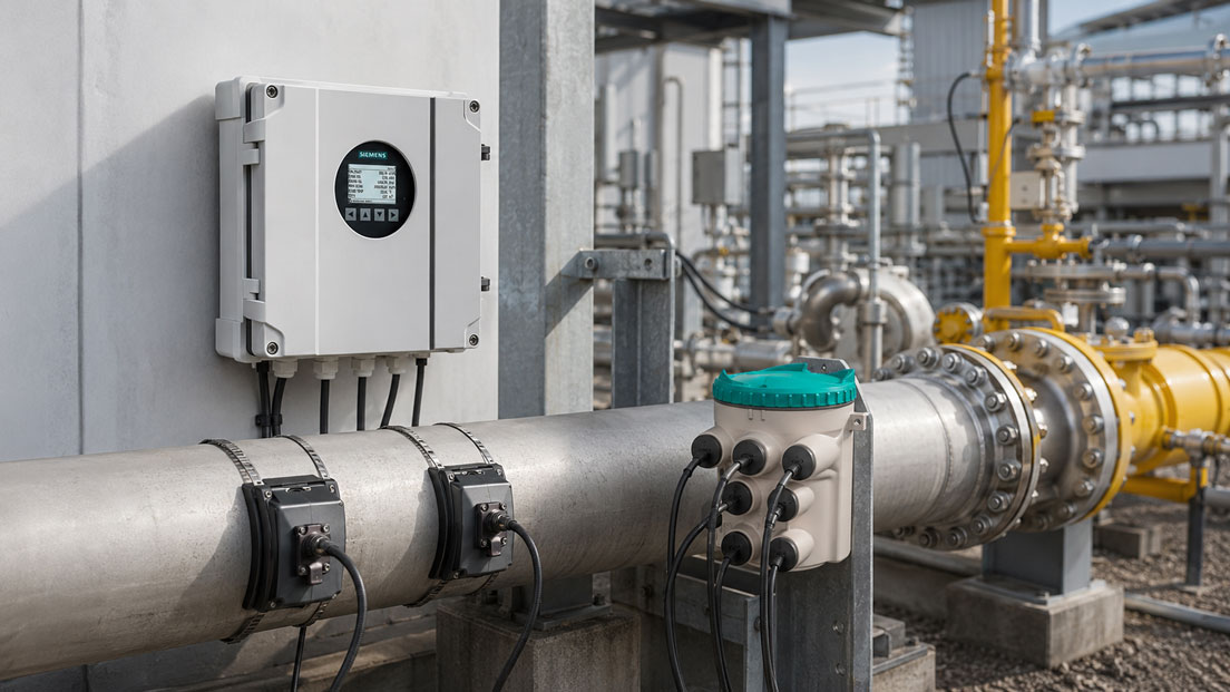
Ultrasonic flowmeters can measure gas flow without moving parts and, in the case of clamp-on systems, even without interfering with the pipeline. The sensors are mounted externally on the pipe, so the line does not need to be opened and no additional pressure loss is generated.
However, what works comparatively easily with liquids is significantly more demanding with gases. The low density of the gas, the acoustic properties of the pipe wall, the operating pressure, the gas composition and the flow velocity determine whether a sufficiently strong and stable ultrasonic signal can be produced.
An ultrasonic gas measurement system should therefore not be selected solely according to pipe diameter and maximum flow. Before configuration, the gas type, operating pressure, temperature, pipe material, wall thickness, installation conditions and required measured variable must be known. Particularly in clamp-on applications, this preliminary assessment determines whether reliable measurement is possible.
Table of Contents
- How does transit-time measurement work with gases?
- Why is gas measurement more difficult than liquid measurement?
- Clamp-on or in-line?
- When is ultrasonic flow measurement useful for gases?
- Correctly considering gas type, pressure and temperature
- Which pipe data are required?
- Installation location and flow profile
- Minimum velocity and measuring range
- Distinguishing between actual volume flow, standard volume flow and mass flow
- Signal strength, speed of sound and diagnostic values
- Typical causes of unstable measured values
- Commissioning and plausibility checks
- Practical example on a process-gas pipeline
- Selecting an ultrasonic flowmeter for gas
- Which measuring instruments / products are suitable?
- Conclusion
- Frequently asked questions
How does transit-time measurement work with gases?
With transit-time measurement, at least two ultrasonic sensors transmit signals diagonally through the pipe and the flowing gas. One signal travels in the direction of flow, while the other travels against the direction of flow.
The signal travelling with the flow reaches the opposite sensor slightly earlier. The signal travelling against the flow takes correspondingly longer. From this transit-time difference, the transmitter calculates the average flow velocity along the ultrasonic path.
The volume flow under the current operating conditions is calculated from the flow velocity and the unobstructed pipe cross-sectional area:
Volume flow = average flow velocity × unobstructed pipe cross-sectional area
The actual transit-time difference is usually very small. The measuring system must therefore determine the signal transmission, pipe geometry and transit times precisely. Inaccurate pipe data or a weak received signal can significantly affect the calculated flow.
Multi-path in-line instruments or advanced clamp-on systems use several ultrasonic paths. This allows the flow profile to be detected more accurately and reduces sensitivity to asymmetrical flow conditions.
Why is gas measurement more difficult than liquid measurement?
Liquids have a significantly higher density than gases and generally transmit ultrasonic signals much more effectively. With clamp-on gas measurement, the signal must first pass through the pipe wall into the gas and then return through the gas into the opposite pipe wall.
A considerable proportion of the acoustic energy is lost at the transitions between the metal pipe and the gas. The lower the gas density, and often therefore the operating pressure, the weaker the received signal may be.
Further differences compared with liquids include:
- The speed of sound depends more strongly on the gas composition and temperature.
- Pressure changes affect gas density and standard volume calculations.
- Low flow velocities produce only very small transit-time differences.
- Pressure-control valves and compressors can generate significant acoustic interference.
- Liquid droplets, condensate or two-phase flow alter the signal.
- The pipe wall, coating and corrosion have a major influence on signal coupling.
An ultrasonic instrument designed for water or other liquids cannot therefore automatically be used for gas. Gas pipelines require special sensors, mounting arrangements and evaluation algorithms.
Clamp-on or in-line?
| Criterion | Clamp-on measurement | In-line measurement |
|---|---|---|
| Installation | Sensors mounted externally on the existing pipeline | The measuring section is installed in the pipeline |
| Process interruption | Generally not required | Required for installation and removal |
| Pressure loss | No additional pressure loss | Usually very low because no components need to protrude into the flow cross-section |
| Measuring geometry | Depends on the existing pipeline and known pipe data | Defined measuring geometry known at the factory |
| Measurement uncertainty | More dependent on the application and installation | Generally more clearly defined and reproducible |
| Typical task | Retrofitting, check metering, process monitoring and temporary measurement | Permanent process measurement, balancing and custody-transfer applications |
Clamp-on measurement is particularly useful when a gas pipeline must not be opened, a measuring point needs to be retrofitted or no additional pressure loss is acceptable. Large nominal pipe sizes and remote measuring points can also be covered economically.
For billing-related measurements, very low measurement uncertainty or difficult low-pressure applications, an in-line ultrasonic meter is often the more suitable solution. Its sensor positions, path lengths and pipe geometry are clearly defined and can be tested or calibrated at the factory.
When is ultrasonic flow measurement useful for gases?
Typical industrial applications include:
- natural-gas and process-gas pipelines,
- utility lines within production plants,
- check metering and comparison with existing gas meters,
- distribution of fuel gas to individual consumers,
- gas supply to power plants, burners or furnaces,
- storage, production and transport pipelines,
- leakage and balance investigations,
- temporary measurement campaigns,
- measurements on large pipelines without interrupting the process.
Clamp-on measurement is particularly advantageous when the existing pipeline is to remain unchanged. The sensors have no direct contact with the gas and are exposed neither to the process pressure nor to chemical attack from the medium.
The method may be less suitable at very low gas pressures, extremely low flow velocities, on severely corroded or acoustically unfavourable pipelines, or where the gas composition varies significantly. Whether measurement is still possible must be assessed using the specific application data.
Correctly considering gas type, pressure and temperature
The precise gas type must be known for configuration. The description “gas” or “process gas” is not sufficient. Natural gas, nitrogen, hydrogen, biogas, compressed air and variable process gases have different speeds of sound, densities and acoustic properties.
For gas mixtures, the composition and expected range of variation should be specified wherever possible. If the composition changes, the speed of sound also changes. This can be relevant both for parameterisation and plausibility checking.
The operating pressure has a particular influence on signal transmission in clamp-on systems. As the gas density increases, the acoustic coupling between the pipe wall and gas often improves. Nevertheless, no universal minimum pressure can be specified because the required conditions depend on the gas, pipe material, wall thickness, sensor frequency and pipe diameter.
At least the following information is therefore required:
- gas type or gas composition,
- minimum, normal and maximum operating pressure as absolute pressure,
- minimum, normal and maximum gas temperature,
- possible moisture or condensate formation,
- expected changes in composition,
- required actual or standard reference conditions.
Condensate can be problematic even when the pressure is generally suitable. Liquid droplets alter the acoustic conditions and may indicate that the gas phase is not homogeneous. With wet gases, it must therefore be checked whether the specific measuring system is suitable for these conditions.
Which pipe data are required?
With clamp-on measurement, the existing pipeline forms part of the measuring system. The transmitter calculates the sensor spacing, acoustic path and unobstructed cross-sectional area from the pipe data.
Important information includes:
- exact outside pipe diameter,
- wall thickness,
- pipe material,
- any internal lining and its thickness,
- external coating or insulation,
- pipe condition, corrosion and deposits,
- nominal pipe size and pressure rating,
- available pipe circumference for sensor installation.
The nominal pipe size alone is not sufficient. Pipes with the same nominal size may have different outside and inside diameters depending on the material, standard and pressure rating.
An incorrect wall thickness changes the calculated ultrasonic path and unobstructed pipe cross-section. This can affect both the signal quality and the calculated volume flow.
For older pipelines, a wall-thickness measurement at the intended sensor position is advisable. Rust, weld seams, paint layers and uneven surfaces must be taken into account before installation. The sensors require a clean and sufficiently smooth contact surface.
Installation location and flow profile
The ultrasonic sensors detect the flow only along their defined measuring paths. A highly asymmetrical or swirling flow profile can therefore lead to deviations.
Disturbances occur particularly downstream of:
- pipe bends and out-of-plane double bends,
- partially closed valves,
- pressure reducers and control valves,
- compressors and blowers,
- T-pieces and pipe junctions,
- sudden changes in cross-section,
- filters or internal components.
The required upstream and downstream straight runs depend on the measuring instrument, the number of paths and the type of disturbance. General specifications stated in pipe diameters can only serve as initial guidance. The manufacturer’s instructions and the specific flow conditions are decisive.
With single-path measurement, the installation location should be as far away from disturbances as possible. Multi-path systems can detect a distorted flow profile more effectively, but do not replace the correct selection of the measuring location.
Pressure-control valves can additionally generate strong ultrasonic or structure-borne noise. The sensors should therefore not be mounted directly adjacent to such a source of interference. During commissioning, it must be checked whether the useful signal is sufficiently distinct from the interference signal.
Minimum velocity and measuring range
The lower the flow velocity, the smaller the transit-time difference between the signal travelling with the flow and the signal travelling against it. At some point, this difference becomes comparable with the signal noise, timing resolution and zero-point stability.
There is therefore no universal minimum velocity for all ultrasonic gas measurements. It depends, among other things, on:
- the measuring system and signal processing,
- pipe diameter and path length,
- number and arrangement of the measuring paths,
- gas type and operating pressure,
- signal-to-noise ratio,
- flow profile and pipe vibration,
- required measurement uncertainty.
During configuration, not only the maximum and normal flow must be specified. The minimum flow that still needs to be measured reliably is equally important. A system may operate very well at normal plant output while providing only unstable values during partial-load operation.
For applications with a wide measuring range, a multi-path system or a sensor specifically designed for low gas velocities may be useful.
Distinguishing between actual volume flow, standard volume flow and mass flow
An ultrasonic flowmeter initially determines the flow velocity and uses it to calculate the volume flow under the current conditions in the pipeline. This value is referred to as the actual or operating volume flow.
With gases, the volume changes with pressure and temperature. A standard or reference volume flow is therefore often required for comparing consumption quantities.
At least the following values are required for conversion:
- absolute operating pressure,
- absolute gas temperature,
- specified standard pressure,
- specified standard temperature,
- where applicable, compressibility factors or a gas model.
In simplified form:
Standard volume flow = actual volume flow × pressure ratio × inverse temperature ratio × compressibility correction
Pressure values must be absolute and temperatures must be expressed in Kelvin. The applicable reference conditions must also be clearly defined. Depending on the application, 0 °C, 15 °C or other standard conditions may be used.
Mass flow can be calculated from the actual volume flow and operating density, or from the standard volume flow and standard density. Unlike a Coriolis flowmeter, an ultrasonic gas meter does not normally measure mass flow directly.
Signal strength, speed of sound and diagnostic values
With ultrasonic gas measurement, the displayed flow should not be considered in isolation. Diagnostic values indicate whether the acoustic signal and measuring conditions are plausible.
| Diagnostic value | Meaning | Possible response |
|---|---|---|
| Signal strength | Amplitude of the received ultrasonic signal | Check the sensor position, coupling, pipe condition and operating pressure |
| Signal-to-noise ratio | Separation between the useful signal and acoustic interference | Increase the distance from valves, compressors or vibration sources |
| Measured speed of sound | Acoustic property of the current gas | Compare it with the expected value for the gas composition and temperature |
| Signal quality | Overall assessment of the transit-time measurement | Do not continue using the measured value without checking it if the quality is poor |
| Path comparison | Comparison of the measured values from several ultrasonic paths | Check the flow profile, contamination or a faulty path |
| Zero-point stability | Behaviour when the gas is genuinely stationary | Check for valve leakage, convection, vibration or incorrect parameterisation |
The measured speed of sound is a particularly valuable plausibility value. If it differs significantly from the value expected for the gas, temperature and composition, possible causes include incorrect gas data, condensate, a changed composition or incorrect path assignment.
With changing gas mixtures, the speed of sound itself can provide important process information. However, it does not replace complete gas analysis.
Typical causes of unstable measured values
The operating pressure is too low for the clamp-on application
At low gas density, only a very weak signal may be transmitted through the pipe wall. The instrument loses the received signal or indicates poor signal quality.
The pipe wall or coating attenuates the signal
Thick steel pipes, corrosion, multi-layer coatings or loose linings can impair ultrasonic transmission.
The pipe data are inaccurate
An incorrect outside diameter or wall thickness results in incorrect sensor spacing, acoustic path and pipe cross-section.
The flow velocity is too low
At very low velocities, the transit-time difference becomes too small to be evaluated reliably against zero-point drift and interference.
The sensors are located too close to a control valve
Acoustic noise and a severely distorted flow profile may interfere with the useful signal.
The gas contains condensate or liquid droplets
A non-homogeneous phase alters the speed of sound, signal strength and flow profile. The measured value may therefore fluctuate or be marked as invalid.
The standard volume calculation uses incorrect pressure values
If gauge pressure is used instead of absolute pressure, or the reference conditions are set incorrectly, the standard volume flow can deviate significantly.
Commissioning and plausibility checks
A systematic procedure is recommended when commissioning a clamp-on gas measurement system:
- Document the gas type, pressure, temperature and flow range.
- Verify the outside pipe diameter, wall thickness, material and coating.
- Select a suitable straight pipe section.
- Prepare the pipe surface and mount the sensors at the calculated spacing.
- Check the signal strength and signal-to-noise ratio.
- Compare the measured speed of sound with the expected value for the gas.
- Check the flow direction and zero point.
- Compare the actual volume flow with the plant output or a reference value.
- For standard volume flow, check the pressure and temperature signals.
- Document the diagnostic values and limits for subsequent operation.
If a complete shutdown is possible, the zero point can be checked with the pipe closed and pressurised. It must be ensured that no gas is actually flowing. Leaking valves, thermal convection or pressure-equalisation processes may otherwise produce an apparent flow.
For important balance or consumption measurements, the ultrasonic measurement should, wherever possible, be compared with a known reference value. A plausible display reading alone does not prove that the required measurement uncertainty has been achieved.
Practical example: Clamp-on measurement on a process-gas pipeline
In a production plant, the nitrogen consumption of one section of the system is to be determined. The existing steel pipeline must not be opened. A clamp-on ultrasonic measuring system is therefore retrofitted on a straight pipe section.
The following data are recorded for configuration:
- Gas: nitrogen,
- Operating pressure: 7 bar absolute,
- Gas temperature: approximately 25 °C,
- Pipe: steel, DN 100,
- Measured outside diameter and wall thickness,
- Flow range: 80 to 900 m³/h under operating conditions.
During the first installation, the signal-to-noise ratio is low and the displayed flow fluctuates. The sensors are located only a few pipe diameters downstream of a pressure-control valve.
After the sensors are relocated to a longer straight pipe section, the signal quality improves significantly. The measured speed of sound corresponds to the expected value for nitrogen at the existing temperature.
The actual volume flow is then converted into the standard volume flow used by the company using the absolute pressure and gas temperature. The measurement is used for internal allocation of consumption and not for legal-metrology billing.
The example shows that not only the type of measuring instrument but especially the pipe data, pressure and installation location determine the quality of a clamp-on gas measurement.
Selecting an ultrasonic flowmeter for gas
At least the following information is required for a reliable instrument configuration:
- gas type and gas composition,
- minimum, normal and maximum operating pressure,
- minimum, normal and maximum gas temperature,
- minimum, normal and maximum flow,
- required output as actual volume flow, standard volume flow or mass flow,
- pipe material, outside diameter and wall thickness,
- lining, coating and pipe condition,
- available straight pipe sections,
- possible moisture or condensate formation,
- required measurement uncertainty,
- temporary, permanent or custody-transfer measurement,
- outputs and communication,
- Ex zone and required approvals.
A clamp-on solution should be technically configured before it is ordered. Particularly at low pressures, with thick pipe walls, low flow rates or unusual gases, the acoustic feasibility must be checked.
Which measuring instruments / products are suitable?
Ultrasonic flowmeters
The ultrasonic flowmeters category includes stationary and portable in-line and clamp-on systems for liquids and selected gas applications.
A system specifically suitable for gas must be selected. An ultrasonic flowmeter for water or other liquids is not automatically suitable for the significantly more demanding signal transmission in gas pipelines.
SITRANS FS230 clamp-on ultrasonic flowmeter
The SITRANS FS230 is a stationary clamp-on system for demanding measurements on liquid and gas pipelines. It is suitable for applications including natural gas, process gases, check metering, distribution, production and storage.
The sensors are mounted externally on the pipeline. Depending on the version and configuration, several measuring paths, bidirectional measurement and values for actual volume flow, standard volume flow, mass flow and speed of sound can be provided.
For gas applications, the system must be configured according to the pipe data, gas, pressure, temperature and flow velocity. For Ex applications, the versions of the sensors, digital sensor module and transmitter, as well as their respective zone approvals, must also be considered.
WIKA Type FLC-UFL
The WIKA Type FLC-UFL is a permanently installed multi-path ultrasonic flowmeter for gases and custody-transfer applications.
The instrument operates with two or more ultrasonic paths and provides the gas flow together with values including speed of sound, signal strength and signal-to-noise ratio for condition monitoring. Pressure and temperature sensors can be connected for integrated volume conversion.
The FLC-UFL is particularly suitable for industrial gases, oil and gas, petrochemicals, energy supply and the process industry where a permanently defined measuring section and low, traceable measurement uncertainty are required.
Flow measurement technology using alternative measuring principles
In addition to ultrasonic systems, the flow measurement technology category includes thermal mass flowmeters, Coriolis systems, vortex flowmeters and other measuring principles.
If reliable clamp-on ultrasonic measurement is not possible due to low gas pressure, an unsuitable pipeline or very low flow, a different measuring principle may be more suitable. The selection depends on the gas, flow range, pressure loss, accuracy and installation conditions.
Conclusion: Ultrasonic gas measurement operates reliably when the application and acoustics are compatible
Transit-time measurement enables wear-free and largely pressure-loss-free measurement of industrial gas flows. Clamp-on systems additionally offer the advantage that they can be retrofitted without opening the pipeline.
However, gases transmit ultrasound significantly less effectively than liquids. The operating pressure, gas composition, pipe material, wall thickness, flow velocity and installation location must therefore be checked before selecting the instrument.
The measured value should always be assessed together with the signal strength, signal-to-noise ratio and measured speed of sound. These diagnostic values often provide an early indication that the process conditions, gas composition or signal transmission have changed.
A dedicated clamp-on gas system such as the SITRANS FS230 may be suitable for check metering, consumption allocation and retrofitting. For custody-transfer applications or particularly precisely defined measuring points, a permanently installed multi-path gas meter such as the WIKA FLC-UFL is the more suitable option.
Frequently asked questions about ultrasonic flow measurement for gases
Can every clamp-on ultrasonic flowmeter also measure gas?
No. Most simple clamp-on instruments are designed for liquids. Gas requires special sensors and evaluation methods because the acoustic coupling between the pipe wall and gas is significantly more difficult.
What minimum pressure is required for clamp-on gas measurement?
There is no universal minimum pressure. The required gas density depends on the gas type, pipe material, wall thickness, diameter, sensor and measuring system. The application must be technically configured.
Can the flow be measured at atmospheric pressure?
This may be possible with certain gases, pipe materials and specialised systems, but it is often very demanding on metallic pipelines. The signal transmission must always be assessed.
Does an ultrasonic gas meter directly measure standard cubic metres per hour?
The measuring principle initially determines the actual volume flow. Standard volume flow additionally requires the absolute pressure, gas temperature, reference conditions and, where applicable, a gas model or compressibility factors.
Why is the measured speed of sound important?
It serves as a plausibility and diagnostic value. Deviations may indicate a changed gas composition, incorrect parameterisation, condensate or inadequate signal evaluation.
Does a pressure-control valve affect the measurement?
Yes. Control valves can severely distort the flow profile and generate acoustic interference. The sensors should be installed at a sufficient distance from such disturbances.
When is an in-line instrument better than a clamp-on system?
An in-line system is often more suitable where low and traceable measurement uncertainty, custody-transfer billing, very low flow or permanently defined measuring geometry are required.
Which information does ICS Schneider require for product selection?
The required information includes the gas type and composition, operating pressure, temperature, flow range, required unit and reference conditions, pipe material, outside diameter, wall thickness, coating, installation conditions, Ex requirements, required outputs and the required measurement uncertainty.