


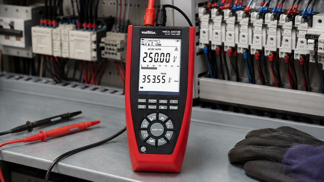
Operating errors occur particularly frequently when measuring current with a multimeter. Unlike a voltage measurement, the instrument is not connected in parallel across two measuring points but inserted into the circuit. The conductor must therefore be interrupted at a suitable point so that the entire current being measured flows through the multimeter.
Many multimeters also have separate input sockets for microampere, milliampere and high-current measurements. If the wrong socket is used, the internal fuse may blow, the measured value may be unusable or the instrument may be damaged in the event of a high-energy operating error. It is particularly dangerous to connect a multimeter prepared for current measurement in parallel with a voltage source as if carrying out a voltage measurement.
Before every current measurement, the expected current level, the correct socket, the appropriate measuring range, the rating of the internal fuse and the electrical measurement category must therefore be clarified. For industrial 4–20 mA current loops, it must also be decided whether the current only needs to be measured or whether a signal must additionally be simulated and the loop supplied with power.
Table of Contents
- Why is current measured in series?
- Distinguishing between voltage and current measurement
- Using the COM, µA, mA and A input sockets correctly
- Selecting the µA, mA and 10 A ranges
- What is the purpose of the internal fuses?
- How can a blown mA fuse be identified?
- How does the multimeter affect the circuit?
- Carrying out current measurements safely
- Typical operating errors
- Measuring 4–20 mA current loops correctly
- Special considerations for µA measurements
- When is a current clamp more suitable?
- Practical example on a 4–20 mA transmitter
- Selecting a multimeter for current measurements
- Which measuring instruments / products are suitable?
- Conclusion
- Frequently asked questions
Why is current measured in series?
Electrical current describes the quantity of electric charge flowing through a conductor or circuit. If this current is to be measured with a multimeter, it must pass through the instrument’s internal measuring path.
To achieve this, the circuit is opened at a suitable point and the multimeter is inserted in series. The current then flows from the circuit through the red test lead, through the multimeter’s internal current-measuring resistor and back into the circuit through the COM lead.
The multimeter does not determine the current directly. Internally, it evaluates the voltage drop across a small measuring resistor known as a shunt. The instrument calculates the current from the resistance and measured voltage.
The shunt must be designed for the respective measuring range. A different internal measuring circuit is used for small currents than for currents in the ampere range. This is why many multimeters have separate sockets and fuses.
Distinguishing between voltage and current measurement
| Criterion | Voltage measurement | Current measurement |
|---|---|---|
| Connection | In parallel with the load or voltage source | In series in the circuit |
| Internal resistance | As high as possible | As low as possible |
| Typical red socket | V/Ω | µA/mA or A/10 A |
| Open the circuit | Not required | Generally required |
| Risk of incorrect connection | Incorrect measuring range or overvoltage | Near short circuit when connected in parallel |
During voltage measurement, the multimeter has a high input resistance and draws only a very small current from the circuit. During current measurement, however, the internal resistance is low so that the voltage drop remains as small as possible.
If a multimeter set for current measurement is connected in parallel with a voltage source, the low internal resistance connects the two measuring points almost directly. The internal fuse is intended to interrupt this fault current. At high energy levels, however, such incorrect operation can still be dangerous.
Using the COM, µA, mA and A input sockets correctly
The black test lead is normally connected to the socket marked COM. Depending on the multimeter, several inputs may be available for the red test lead.
| Input socket | Typical use | Important note |
|---|---|---|
| V/Ω | Voltage, resistance, continuity, diode and, where applicable, frequency | Do not use for direct current measurement |
| µA/mA | Small direct or alternating currents | Usually separately fused and only suitable up to the specified limit |
| mA | Milliampere measurements and frequently 4–20 mA signals | Observe the maximum current and fuse rating |
| A or 10 A | Higher currents | Measurement duration is often limited; the fuse design depends on the model |
The labelling differs depending on the instrument. Some multimeters have one shared socket for µA and mA, while others separate the two ranges. The maximum rating may also be 400 mA, 600 mA or another instrument-specific value.
Automatic range selection does not replace selecting the correct socket. The multimeter may automatically select the appropriate numerical range, but it cannot internally transfer the red test lead from the V/Ω socket to the mA input.
The combination of socket, rotary-switch position and expected current level must therefore always be checked before measurement.
Selecting the µA, mA and 10 A ranges
For good resolution, the smallest measuring range that still safely covers the expected current should be used. If the current is unknown, however, the measurement should initially be started with the highest suitable current range.
The units are related as follows:
- 1 A = 1,000 mA
- 1 mA = 1,000 µA
- 1 A = 1,000,000 µA
A current of 0.015 A therefore corresponds to 15 mA or 15,000 µA.
The 10 A input is not automatically the best choice for every current measurement. A value of 12 mA will often only be displayed with poor resolution in this range. The fused mA input is therefore normally more suitable for a 4–20 mA current loop.
Conversely, an unknown load current must not be tested through the sensitive µA or mA socket. If it exceeds the permissible input current, the fuse will blow. If an unsuitable fuse is installed or the instrument limits are exceeded, the multimeter may be damaged.
For high currents, the permissible duty cycle must also be observed. Some multimeters allow measurements in the 10 A range only for a limited period and require a cooling interval afterwards. The operating instructions for the specific instrument are decisive.
What is the purpose of the internal fuses?
The fuses protect the current-measuring inputs against overload and incorrect operation. They form part of the multimeter’s safety concept and must be suitable for the possible voltage, breaking capacity and measurement category.
High-quality multimeters intended for high-energy measuring environments often use ceramic high-performance fuses with a defined breaking capacity. A visually similar glass fuse is not a permissible replacement if the manufacturer specifies a different type.
When replacing a fuse, all specifications must correspond:
- rated current,
- rated voltage,
- tripping characteristic,
- breaking capacity,
- dimensions and design,
- manufacturer approval or instrument specification.
A blown fuse must never be bridged or replaced with wire. This would disable the protective function. In the event of another operating error, PCB tracks, test leads or the housing could carry the fault current.
The A or 10 A input is also not fused in the same way on every multimeter. Some instruments have a separate high-current fuse, while others have different operating limits. The instrument marking and operating instructions must therefore always be observed.
How can a blown mA fuse be identified?
After an overload, it is often only the current measurement function that stops working. Voltage, resistance and continuity measurements may continue to operate normally because they use a different input path.
Typical indications of a blown mA fuse include:
- The multimeter permanently displays 0 mA despite a closed circuit.
- The connected 4–20 mA loop is interrupted by the multimeter.
- A measurement through the A input works, but not through the mA input.
- The circuit works again as soon as the multimeter is bypassed or removed.
- The instrument’s internal fuse test reports a fault.
All test leads must be removed before opening the multimeter. The fuse must only be checked and replaced in accordance with the operating instructions. For multimeters intended for high measurement categories, the repair should, in case of doubt, be carried out by a suitable service centre.
A new fuse should only be installed once the cause has been identified. A common cause is that voltage was measured while the red lead was still inserted in the mA socket.
How does the multimeter affect the circuit?
During current measurement, the multimeter has an internal shunt as well as additional resistances from the fuse, leads and contacts. This causes an additional voltage drop, also known as burden voltage.
In a high-power circuit, this voltage drop is often small in relation to the supply voltage. In electronic circuits with a low supply voltage or very small sensor signals, however, it can noticeably affect operation.
Possible effects include:
- The supply voltage at the load decreases.
- A sensor no longer starts correctly.
- The current consumption appears lower than during normal operation.
- A battery-powered circuit changes to a different operating state.
- The measured value changes when switching between the µA and mA ranges.
For sensitive µA measurements, a multimeter with low burden voltage and suitable resolution is therefore important. The relevant value should be checked in the data sheet for the measuring range being used.
Carrying out current measurements safely
Measurements on high-energy or live circuits may only be carried out by appropriately qualified persons. Wherever possible, the circuit should be isolated before the leads are reconnected and the instrument is installed.
- Determine the measurement task: Clarify whether the current is AC or DC, its expected level and the required resolution.
- Check the instrument: The measurement category, maximum voltage, current range and fuse must be suitable for the application.
- Isolate the circuit: Switch off the voltage and establish a safe condition before opening the conductor path.
- Connect the test leads: Black to COM and red to the appropriate µA, mA or A socket.
- Select the measuring function: Set direct or alternating current and initially choose a sufficiently high range.
- Open the circuit: Insert the multimeter in series at a suitable point.
- Secure the connections: Wherever possible, use suitable test clips before energising the circuit.
- Carry out the measurement: Switch on the circuit and observe the measured value and any warning indications.
- Isolate the circuit again: Switch it off again before removing the test leads.
- Reset the multimeter: Afterwards, return the red test lead to the V/Ω socket.
The final step prevents one of the most common operating errors: voltage is measured during the next task while the red lead is still connected to the low-resistance current input.
Typical operating errors
The multimeter is connected in parallel with a voltage source
The current input has a very low resistance. A parallel connection can therefore cause a short circuit and blow the internal fuse.
The red lead is still inserted in the mA socket
The rotary switch is set to voltage, but the lead remains in the current input. Depending on the instrument, merely contacting the measuring point may cause a fault current.
An unknown current is measured in the µA range
If the actual current is significantly higher than expected, the sensitive measuring range is overloaded. For unknown values, a sufficiently high range should initially be selected.
The 10 A range is subjected to continuous load
Many handheld multimeters are not designed for unlimited high-current measurement. The permissible measurement duration and required cooling interval must be observed.
An incorrect replacement fuse is used
A fuse of the correct physical size but with insufficient breaking capacity may fail at high fault currents. Only the specified type may be installed.
The multimeter is used in an unsuitable measurement category
A sufficient current range provides no information about the permissible transient stress at the measuring point. The CAT rating and nominal voltage must also be suitable.
AC and DC measurement are confused
Direct current measured in the AC range or alternating current measured in the DC range may result in zero, fluctuating or significantly incorrect readings. Not every multimeter supports both current types in every measuring range.
Measuring 4–20 mA current loops correctly
In a 4–20 mA current loop, the process value is transmitted as a direct current. A value of 4 mA normally represents the lower range value and 20 mA the upper range value of the transmitter.
The measuring instrument must also be connected in series here. Connecting it in parallel across the signal terminals would almost short-circuit the loop and could affect the measurement, power supply or analogue input.
There are several possible measurement methods:
- Open the circuit at a suitable disconnect terminal and insert the multimeter in series,
- use existing mA test sockets or test terminals,
- measure the current indirectly as a voltage across a designated measuring resistor,
- use a specialised current-loop calibrator.
The percentage process value can be calculated from the measured current:
Percentage value = (current − 4 mA) / 16 mA × 100%
A current of 12 mA therefore corresponds to 50 per cent of the configured measuring range.
A multimeter can measure the existing loop current. However, it cannot normally simulate a transmitter, power a passive loop or generate an automatic signal ramp. For commissioning, loop checks and troubleshooting, the Druck UPS4E current-loop calibrator is therefore more suitable.
Special considerations for µA measurements
Microampere currents occur, for example, in quiescent-current measurements, battery-powered devices, ionisation monitoring systems and sensitive electronic circuits.
Small interference effects have a greater influence during these measurements:
- leakage currents across contaminated circuit boards or damp surfaces,
- electromagnetic interference,
- unsuitable or long test leads,
- contact resistance and unstable clips,
- the multimeter’s burden voltage,
- changing operating states of the device under test.
Devices with a sleep mode must also be measured over a sufficiently long period. A brief average may be unusable if a quiescent current of only a few microamperes alternates with brief current peaks in the milliampere range.
The measuring range must tolerate both conditions. Otherwise, the µA fuse may blow when the device wakes up or the display may indicate overload.
When is a current clamp more suitable?
A current clamp detects the magnetic field around a conductor. The circuit does not need to be opened. This is an important advantage, particularly for higher currents, operating machinery and high-energy installations.
A current clamp is often more suitable for:
- motor and heating currents,
- distribution boards and supply cables,
- currents in the single- or double-digit ampere range,
- measurements without interrupting the process,
- current profiles when loads are started.
A conventional current clamp is generally not sufficiently sensitive for µA or low mA currents. Special leakage-current clamps can measure significantly smaller alternating currents, but they do not automatically replace direct DC measurement in a 4–20 mA loop.
Practical example: Testing the 4–20 mA signal from a transmitter
A pressure transmitter is configured for a measuring range of 0 to 10 bar. The PLC continuously indicates 0 bar even though the process pressure is approximately 5 bar.
The technician safely isolates the circuit, opens the current loop at a disconnect terminal and connects the multimeter in series using the COM and mA sockets. After switching the circuit back on, the instrument displays 12.02 mA.
This value corresponds to approximately 50 per cent of the measuring range and therefore around 5 bar. The transmitter and loop current are initially plausible. The fault is probably located in the analogue input, the wiring downstream of the measuring point or the PLC scaling.
To narrow down the fault further, the multimeter is removed and a current-loop calibrator is connected. Values of 4 mA, 12 mA and 20 mA are then simulated in succession.
The PLC correctly indicates 0 bar at 4 mA, but only 3 bar at 12 mA and 6 bar at 20 mA. The check reveals that the analogue input in the PLC was scaled for 0 to 20 mA instead of 4 to 20 mA.
The example illustrates the difference between current measurement and signal simulation: the multimeter checks the current actually present, while the current-loop calibrator tests the downstream input independently of the transmitter.
Selecting a multimeter for current measurements
The following points in particular should be checked when selecting a suitable multimeter:
- smallest and largest required current range,
- resolution in the µA and mA ranges,
- support for AC, DC or AC+DC,
- separate and fused current sockets,
- type and breaking capacity of the fuses,
- permissible measurement duration in the high-current range,
- burden voltage in the low-current ranges,
- TRMS measurement for non-sinusoidal alternating currents,
- measurement category and nominal voltage,
- warning for incorrectly inserted test leads,
- MIN/MAX, peak or data-logging functions,
- degree of protection and mechanical robustness.
A particularly high ampere range is not automatically more important than good resolution in the mA or µA range. The measuring instrument should be selected to suit the tasks that actually occur.
Which measuring instruments / products are suitable?
Digital multimeters
The digital multimeters category includes instruments for maintenance, troubleshooting and electrical measurements in a variety of applications.
The models differ in their current ranges, resolution, fuse design, measurement category, TRMS function, input protection and additional functions. Before selection, it should therefore be checked whether the specific instrument has a suitable µA or mA input and the required fuse protection.
Druck UPS4E current-loop calibrator
The Druck UPS4E is specifically designed for testing and troubleshooting 0–20 mA and 4–20 mA current loops.
It can measure existing current signals and output defined mA values. It can also provide a 24 V loop supply. This allows transmitters, PLC inputs, indicators and actuators to be tested more specifically than with a conventional multimeter.
A suitable digital multimeter remains the more versatile instrument for general voltage, resistance and current measurements. For recurring work on industrial current loops, however, a current-loop calibrator provides more specialised functions.
Conclusion: The correct socket is just as important as the measuring range when measuring current
Current is measured with the multimeter connected in series. The instrument must become part of the circuit. A parallel connection, as used for voltage measurement, can cause a short circuit and blow the internal fuse.
Before measurement, the red test lead must be inserted into the appropriate µA, mA or A socket and a sufficiently high measuring range selected. For unknown currents, the highest suitable range should initially be used.
The internal fuses are safety-critical components. They must only be replaced with the specified type and must never be bridged. After the mA fuse has blown, other multimeter functions may continue to operate even though current measurement is no longer possible.
For small currents, the burden voltage must also be considered. The multimeter may affect the circuit under test so significantly that its current consumption changes during the measurement.
A suitable multimeter can be used for a straightforward check of existing 4–20 mA signals. If current signals need to be simulated, passive loops supplied with power or automatic test sequences carried out, a specialised current-loop calibrator is the better solution.
Frequently asked questions about mA and µA measurement with a multimeter
Why must the multimeter be connected in series for current measurement?
The current being measured must flow through the multimeter’s internal measuring resistor. The circuit is therefore opened and the instrument inserted into the conductor path.
What happens if I measure current in parallel with a voltage source?
The low-resistance current input creates an almost direct short circuit. In the best case, the internal fuse blows. At high energy levels, electrical arcing, instrument damage or injury may also occur.
Why does voltage measurement still work even though the mA range is defective?
Voltage and current measurements use different internal input paths. A blown mA fuse may therefore interrupt only the current-measuring range.
Can I install any fuse in the multimeter?
No. The rated current, voltage, tripping characteristic, breaking capacity and dimensions must comply with the manufacturer’s specification. A simple glass fuse may be unsuitable even if it has the correct dimensions.
Should I use the 10 A input for 20 mA?
The measured value may fall within the range, but it will often be recorded with significantly lower resolution. The fused mA input is normally more suitable for 4–20 mA signals.
How do I measure a 4–20 mA signal?
The measuring instrument is inserted in series into the current loop. The loop must be opened at a suitable disconnect point. The mA input must not be connected in parallel across the signal terminals.
Why does the current change as soon as I connect the multimeter?
The internal shunt creates an additional voltage drop. Particularly in circuits with a low supply voltage or high resistance, this burden voltage can alter the operating state.
When should a current-loop calibrator be used instead of a multimeter?
A current-loop calibrator is useful when 4–20 mA signals need not only to be measured but also simulated, generated or supplied using an internal loop power supply.