


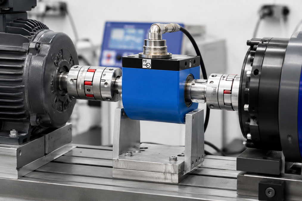
A torque sensor in a test bench is not merely an electrical measuring instrument. It is installed as a mechanical component directly in the power transmission path between the drive, the device under test and the loading machine. Its design therefore influences not only the measuring range and accuracy, but also the shaft spacing, coupling selection, alignment, permissible rotational speed, torsional stiffness and the dynamic behaviour of the entire test bench.
For rotating measurement tasks, the main options are measuring shafts, measuring flanges and sensors with adapted coupling or hub systems. A compact measuring shaft can often be installed easily between two shaft ends. A measuring flange offers advantages at high torques and where the available axial installation length is limited. A coordinated coupling system can simplify mechanical integration, but it must be suitable for the rotational speed, misalignment, torsional stiffness and load changes.
The selection must therefore not be based solely on the nominal torque. A sensor with a sufficient measuring range may still be unsuitable if its maximum rotational speed is too low, the couplings introduce excessive transverse forces or a torsional resonance lies within the operating range of the test bench.
Suitable products can be found in the torque sensors category. Further sensors for rotational speed, force, displacement and vibration are grouped together in the displacement, force, rotational-speed, torque and vibration sensors section.
Contents
- What does a torque sensor measure?
- Distinguishing between static and dynamic torque
- Measuring shaft: universal and easy to integrate
- Measuring flange: compact at high torques
- Torque sensor with coupling system
- Comparing measuring shafts, measuring flanges and coupling systems
- Selecting the measuring range and overload correctly
- Measuring rotational speed and mechanical power
- Bandwidth, load changes and torsional vibrations
- Alignment and unwanted forces
- Sizing couplings correctly
- Defining the installation position in the test bench
- Output signals and data acquisition
- Calibration and zero-point verification
- Practical example: Motor and gearbox test bench
- Selection guide for torque sensors
- Which products are suitable?
- Conclusion
- Frequently asked questions
What does a torque sensor measure?
Torque describes the turning effect of a force on a shaft. It is specified in newton metres and is fundamentally derived from the force and effective lever arm:
M = F × r
Where:
- M = torque in Nm,
- F = tangential force in N,
- r = effective lever arm in m.
In a rotating torque sensor, the torque is usually measured via the slight elastic torsion of a defined measuring body. Strain gauges are installed on this measuring body. The twisting changes their electrical resistance. A measuring bridge and the downstream electronics convert this change into a usable output signal.
For rotating measurement, the signal must be transmitted from the rotating measuring body to the stationary data-acquisition system. Depending on the sensor, this can be achieved using slip rings, inductive transmission, telemetry or electronics fully integrated into the rotor.
Alternatively, a reaction torque sensor can be used. It is not located in a freely rotating shaft, but measures the reaction torque on a stationary housing, bearing arrangement or loading device. This solution must be assessed differently from a rotating measuring shaft from a design perspective.
Distinguishing between static and dynamic torque
A constant torque changes only slightly during the measurement period under consideration. Typical examples include a continuously loaded drive, a slow-running agitator or the determination of a steady-state operating point.
Dynamic torque, by contrast, changes rapidly. It occurs, for example, during:
- start-up and braking processes,
- rapid load changes,
- gear-changing processes,
- combustion or compression cycles,
- screwdriving processes,
- periodic pump and compressor loads,
- torsional vibrations in the drivetrain.
For dynamic measurement, high static accuracy alone is not sufficient. The sensor, amplifier and data-acquisition system must also provide sufficient bandwidth and sampling rate. A heavily filtered signal may appear very stable at constant torque while completely suppressing short torque peaks.
Before selecting the instrument, it must therefore be clarified whether only mean values and steady-state characteristic curves are required or whether rapid peaks, vibrations and load changes are to be investigated.
Measuring shaft: universal and easy to integrate
A measuring shaft has mechanical shaft connections on both sides. It is installed directly in the rotating drivetrain and connected to the drive and load using couplings. Depending on the version, keyed shafts, clamping hubs, splines or other shaft-hub connections are available.
The measuring shaft is particularly suitable for:
- motor and gearbox test benches,
- friction-torque measurements on bearings and gearboxes,
- testing pumps and compressors,
- screwdriving and assembly tools,
- temporary measurements on rotating machinery,
- production and end-of-line testing.
A major advantage is the comparatively straightforward mechanical integration. The sensor can often be installed between two commercially available flexible couplings. However, the shaft ends, coupling bores and axial installation length must be carefully matched.
At high rotational speeds, the mass and diameter of the measuring shaft become increasingly important. The complete rotor consisting of the sensor, couplings and connection hubs must be adequately balanced. The permissible rotational speed of the couplings and clamping sets must also not be lower than the sensor speed.
A measuring shaft usually requires more axial installation length than a measuring flange. In return, it is often flexible to use at low and medium torques and can be converted more easily for changing test tasks.
Measuring flange: compact at high torques
A measuring flange is installed directly in the drivetrain via flange connections. Instead of long shaft ends, it has short, large-area connection geometries. This enables the sensor to achieve a short axial installation length despite a high torque capacity.
Measuring flanges are particularly suitable for:
- high nominal torques,
- high-performance motor and gearbox test benches,
- limited axial installation space,
- high requirements for torsional stiffness,
- permanently installed production or development test benches.
The large connection geometry enables rigid torque transmission. This can be advantageous for dynamic measurements because the additional elastic twisting of the sensor and its connections remains low.
However, the mechanical design is more demanding than with a small measuring shaft. The flange pattern, centring, bolts, preload and contact surfaces must be precisely defined. Even minor contamination or damage on the centring surfaces can impair runout and alignment.
Measuring flanges are often more closely integrated into a specific test bench. Changing to a different torque range at a later stage may therefore require more extensive mechanical modifications.
Torque sensor with coupling system
With a coordinated coupling system, the sensor, couplings and, where applicable, connection hubs are considered as a single mechanical unit. This does not necessarily mean that the coupling is permanently integrated into the sensor. The decisive factor is that all components are matched in terms of torque, rotational speed, stiffness, misalignment and mass moment of inertia.
Such a system can simplify installation and reduce typical sizing errors. Particularly in compact test benches or frequently repeated setups, it is advantageous if the shaft connections, coupling distances and mounting arrangements have already been defined.
A coupling performs several functions:
- transmitting torque without backlash or with defined backlash,
- compensating for small axial, radial or angular misalignment,
- keeping unwanted bending and axial forces away from the sensor,
- enabling assembly and disassembly,
- electrically or thermally isolating the drivetrain where required.
However, a coupling system must not be regarded as a substitute for correct alignment. Flexible couplings can compensate for only limited deviations. Significant alignment errors increase bearing forces, heating and vibration and may damage the sensor.
Comparing measuring shafts, measuring flanges and coupling systems
| Criterion | Measuring shaft | Measuring flange | Coordinated coupling system |
|---|---|---|---|
| Typical application | Universal test benches and rotating machinery | High torques and permanently installed test benches | Compact or recurring installation situations |
| Axial installation length | Usually greater | Frequently short | Depends on the complete system |
| Mechanical adaptability | Good due to different couplings | Flange geometry largely fixed | Optimised for defined connections |
| Torsional stiffness | Depends on the shaft and couplings | Frequently high | Determined jointly by the sensor and couplings |
| Conversion for other devices under test | Comparatively flexible | Often requires greater modification | Simple if suitable interchangeable hubs are provided |
| High rotational speeds | Possible with suitable balancing | Well suited with the appropriate approval | All individual components must be approved |
| Installation effort | Moderate | High demands on centring and bolted assembly | Lower if fully preconfigured |
The design alone does not determine the measurement quality. A correctly installed measuring shaft can provide better results than a high-quality measuring flange with inadequate centring. Conversely, at very high torques, a rigid measuring flange may be considerably more suitable from a design perspective than a long shaft arrangement.
Selecting the measuring range and overload correctly
The nominal torque range should match the actual operating range as closely as possible. Although a very large sensor provides high mechanical load capacity, only a small proportion of its output signal is used at low torques.
If, for example, a 1,000 Nm sensor is operated continuously at only 20 to 50 Nm, this corresponds to just 2 to 5% of full scale. Accuracy, zero-point and hysteresis components specified as percentages of full scale then have a comparatively strong effect on the measured value.
At least the following information is required for selection:
- lowest relevant torque,
- typical operating torque,
- maximum steady-state torque,
- short-term load and start-up peaks,
- torque in both directions of rotation,
- possible blocking or fault conditions.
The measuring range and permissible overload are not the same. The overload limit describes a short-term permissible load at which the sensor is not immediately damaged. It is not an additional measuring range in which the specified accuracy continues to apply.
In the event of sudden blocking, considerably higher torques can occur than during normal operation. If such events are possible, mechanical overload protection, a slipping clutch, torque limitation or a rapid shutdown function must be provided.
Measuring rotational speed and mechanical power
Mechanical shaft power cannot be determined from torque alone. The corresponding rotational speed at the same point in time is also required.
For a rotating shaft:
P = M × ω
With torque in Nm and rotational speed in min−1, the power can be calculated as follows:
P [kW] = M [Nm] × n [min−1] / 9,550
At 100 Nm and 3,000 min−1, for example:
P = 100 × 3,000 / 9,550 = 31.41 kW
Some torque sensors additionally provide a rotational-speed or pulse signal. Alternatively, a separate rotational-speed sensor can be used.
For dynamic tests, torque and rotational speed must be acquired synchronously. Different sampling rates, filter times or time stamps can produce incorrect power peaks and even apparent efficiencies of more than 100%.
Bandwidth, load changes and torsional vibrations
The drivetrain of a test bench consists of several elastic and inertial components. The motor rotor, couplings, sensor, device under test and loading machine together form a torsionally flexible mechanical system.
This system has natural frequencies. If they are excited by load changes, gear meshing, combustion impulses or controller movements, torsional vibrations can occur. The torque at the sensor may then fluctuate considerably more than the mean value suggests.
For dynamic measurements, the following must therefore be considered:
- measurement bandwidth of the sensor,
- sampling rate of the data-acquisition system,
- analogue and digital filters,
- torsional stiffness of the couplings,
- mass moments of inertia of all rotating components,
- possible natural frequencies of the shaft train,
- maximum amplitude of short-term torque peaks.
A soft coupling can damp vibrations or decouple the drivetrain. At the same time, however, it changes the natural frequency and can cause additional twisting. A particularly rigid coupling improves direct transmission, but transfers shocks more strongly to the sensor.
Alignment and unwanted forces
The measuring body of a torque sensor is designed for torsion. Additional axial forces, radial forces and bending moments can influence the measured value and place a load on the bearings or measuring structure.
The installation must therefore be as coaxial and free from mechanical stress as possible. The following must be checked:
- radial parallel misalignment,
- angular misalignment,
- axial position of the shaft ends,
- radial runout of the connection surfaces,
- axial runout of flanges,
- thermally induced changes in length,
- bearing movement under load.
Alignment should not be performed only when the system is cold and stationary. As the system heats up, the motor, gearbox and bearing blocks may expand and change position. In demanding test benches, alignment under operating-temperature conditions must therefore be taken into account.
The sensor housing must also not be subjected to excessive mechanical stress. For sensors with a stationary housing section, the torque support or housing mounting must be installed in accordance with the assembly instructions.
Sizing couplings correctly
The coupling must be capable of transmitting at least the maximum operating torque and peak torque. The maximum rotational speed, permissible misalignment, torsional stiffness, mass moment of inertia and balancing quality must also be checked.
Typical coupling designs include:
- metal bellows couplings for backlash-free and torsionally rigid connections,
- disc couplings for high rotational speeds and torques,
- elastomer couplings for damping shocks and vibrations,
- Oldham or compensating couplings for limited parallel misalignment,
- rigid couplings for very precisely aligned shafts.
Two couplings are frequently required between the sensor and the test bench. They reduce the transmission of unwanted forces and simplify installation. The sensor must not be used as a mechanical bearing unless its design expressly permits this.
Clamping hubs and shrink discs often enable backlash-free connections. Keyed connections are robust and simple, but depending on the design, they may produce backlash or local stress concentrations under alternating loads.
Defining the installation position in the test bench
The sensor always measures the torque at its actual installation position. Losses in bearings, couplings, belts or gearbox stages between the sensor and the device under test are either included or excluded from the result, depending on which side of the sensor they are located.
A typical arrangement is:
Drive → coupling → torque sensor → coupling → device under test → loading machine
For a gearbox test bench, a second measuring point may be required for direct efficiency determination:
Drive → input torque sensor → gearbox → output torque sensor → loading machine
With synchronously measured rotational speed, the input and output power can be calculated. The mechanical efficiency is:
η = Pout / Pin × 100%
The installation position should also provide safe access to cables, connectors and mounting points. Rotating parts require a suitable protective cover. This must not touch the sensor and must provide adequate protection even in the event of a coupling failure.
Output signals and data acquisition
Depending on the design, torque sensors can provide different signals. These include, for example:
- unamplified strain-gauge bridge signals,
- analogue voltage or current signals,
- frequency or pulse signals,
- manufacturer-specific sensor interfaces,
- digital communication interfaces.
When selecting the system, the signal type is not the only important factor. The data-acquisition system and measuring amplifier must also be suitable for the bandwidth, power supply, electrical isolation and required number of channels.
For power calculations, the torque and rotational-speed channels should use the same time base. Where several sensors are used, for example at the input and output of a gearbox, synchronous multi-channel acquisition is particularly important.
The raw values should also be stored. If only the calculated power is recorded, subsequent anomalies caused by signal filters, speed dropouts or torque peaks are difficult to trace.
Calibration and zero-point verification
A torque sensor is usually calibrated using defined torques. For this purpose, a known force is applied through a known lever arm or a suitable torque reference. The sensor value is compared with the reference.
The calibration can assess, among other things:
- zero point,
- sensitivity and span,
- linearity,
- hysteresis,
- repeatability,
- behaviour in both directions of rotation.
After installation, the zero point should be checked with the drivetrain completely unloaded. A significant zero-point offset may indicate mechanical stress, cable problems, unsuitable housing mounting or a residual load that is still present.
An electronic zero adjustment must not simply conceal mechanical preloading. It must first be checked whether the test bench is genuinely unloaded and correctly aligned.
The calibration interval depends on the frequency of use, load spectrum, overloads, required measurement uncertainty and internal test-equipment monitoring. After a significant overload or mechanical damage, the sensor should be checked regardless of the regular interval.
Practical example: Motor and gearbox test bench
An electric motor is to be tested together with a reduction gearbox. During normal operation, 60 to 180 Nm is present at the motor output at speeds of up to 5,000 min−1. During rapid acceleration, approximately 260 Nm may occur briefly.
A sensor with a nominal torque of 1,000 Nm is initially considered. It provides a large overload reserve, but would be utilised at only 6 to 18% during normal operation. This would unnecessarily increase the relative measurement uncertainty.
Instead, a rotating measuring shaft is selected with a measuring range that covers the normal operating range well while providing sufficient reserve for the known start-up peaks. The actual overload limit is also compared with a possible blocking condition.
The sensor is installed between the motor and gearbox. Two backlash-free compensating couplings reduce the introduction of bending and axial forces. The motor, sensor bearing block and gearbox are first aligned geometrically and then checked at operating temperature.
The rotational speed is measured using a separate pulse encoder. The torque and speed channels are recorded synchronously so that the instantaneous input power can be calculated. A second coordinated measuring point is provided at the output to determine the gearbox efficiency.
During the initial load changes, noticeable periodic torque peaks occur. A frequency analysis reveals a torsional resonance close to a frequently used operating speed. The critical range is shifted by adjusting the coupling stiffness and controller parameters.
This example shows that selecting a torque sensor is not complete once the correct Nm range has been chosen. The sensor, couplings, speed measurement, mechanics and data acquisition form a complete test-bench system.
Selection guide for torque sensors
For reliable sizing, at least the following information should be available:
- minimum, typical and maximum torque,
- expected torque and shock peaks,
- measurement in one or both directions of rotation,
- minimum, normal and maximum rotational speed,
- static or dynamic measurement task,
- required measurement bandwidth and sampling rate,
- available axial and radial installation space,
- shaft or flange dimensions,
- permissible parallel, angular and axial misalignment,
- required coupling design,
- ambient and operating temperature,
- ingress protection and environmental conditions,
- required output signal,
- additional speed or direction-of-rotation measurement,
- calibration and documentation requirements.
These data can be used to determine whether a compact measuring shaft, a rigid measuring flange or a coordinated sensor-coupling system is the better solution.
Which products are suitable?
The torque sensors category contains rotating sensors for test benches, machinery and industrial monitoring tasks.
HySense TQ100 rotating torque sensor
The HySense TQ100 operates according to the strain-gauge principle with slip-ring transmission. It has integrated direction detection and is intended for constant and varying torques on rotating shafts.
The available measuring range extends from 1 to 500 Nm. The measurement accuracy is specified as 0.1% of full scale. Keyed connections on both sides allow the sensor to be integrated into suitable shaft trains and test-bench setups.
HySense TQ110 rotating torque sensor
The HySense TQ110 is also designed as a rotating torque sensor with slip-ring transmission. The series is specified with an error limit of 0.1% of full scale and repeatability of ±0.05%.
The specific version must be selected according to the torque range, rotational speed, shaft connections and required measuring chain.
Rotational-speed sensors and additional measured variables
To calculate mechanical power, the torque sensor can be combined with a sensor from the rotational-speed sensors and tachometers category.
The wider displacement, force, rotational-speed, torque and vibration sensors section also contains sensors for measuring additional test-bench variables. These include force, position and vibration.
Measuring flanges and specially coordinated coupling systems must be designed on a project-specific basis. The sensor, mechanical interfaces, couplings, rotational speed and expected dynamic behaviour must be considered together.
Conclusion: The torque sensor is part of the mechanical test bench
The correct design depends on more than just the torque range. Measuring shafts, measuring flanges and coupling systems differ in installation length, torsional stiffness, connection geometry, maximum rotational speed and mechanical integration effort.
Measuring shafts are flexible and suitable for many test benches. Measuring flanges offer advantages at high torques, where little axial installation space is available and rigid test-bench structures are required. A coordinated coupling system simplifies integration and keeps unwanted forces away from the sensor.
The measuring range, overload and actual torque peaks must be assessed separately. An unnecessarily large measuring range reduces the relative measurement quality at low loads. A nominal overload reserve does not replace protection against blocking or shock torques.
For dynamic tests, the bandwidth, sampling rate, torsional vibrations and synchronous speed measurement are also decisive. Only torque and speed values recorded at the same point in time enable reliable calculation of the mechanical power.
A reliable test-bench solution therefore results from the complete system: the torque sensor, couplings, alignment, bearing arrangement, rotational-speed measurement, signal conditioning, data acquisition and calibration must all be compatible.
Frequently asked questions about selecting torque sensors
When is a measuring shaft suitable?
A measuring shaft is suitable for many universal motor, gearbox and machinery test benches. It can be installed between two shaft ends using suitable couplings and is particularly flexible for low and medium torques.
When is a measuring flange useful?
A measuring flange is particularly suitable for high torques, limited available installation length and high torsional-stiffness requirements. The flange pattern, centring and bolted connection must precisely match the test bench.
Why are two couplings used with a torque sensor?
The couplings transmit the torque and compensate for limited alignment deviations. This reduces axial, radial and bending forces on the sensor. Correct alignment of the test bench remains necessary.
How should the measuring range be selected?
The typical operating range should use a sufficiently large proportion of the sensor’s nominal range. Known load peaks and fault conditions must also be taken into account. The largest possible sensor is not automatically the most accurate solution.
Can a torque sensor also measure power?
Rotational speed is additionally required to determine power. The mechanical shaft power can be calculated from synchronously measured torque and rotational speed.
What does dynamic torque mean?
Dynamic torque changes rapidly, for example during load steps, gear changes or torsional vibrations. Sufficient sensor bandwidth and a suitably fast data-acquisition system are required to measure it.
Why does the sensor show a zero-point offset after installation?
Possible causes include mechanical stress, poor alignment, unwanted axial or bending forces, incorrect housing mounting or a residual load that is still present. The cause should be investigated before an electronic zero adjustment is performed.
When must a torque sensor be recalibrated?
The interval depends on the load, frequency of use and accuracy requirements. After a significant overload, mechanical damage or a noticeable change in the zero point, the sensor should be checked regardless of the regular interval.