


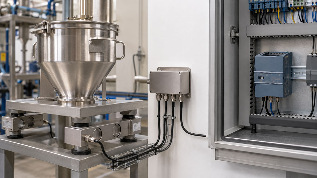
A load cell does not yet provide a weight value that can be used directly by a PLC. Its output usually consists of a very small strain-gauge bridge signal in the range of only a few millivolts. This signal must be supplied with a stable excitation voltage, amplified, filtered, digitised and then converted into kilograms, tonnes or another unit of weight.
This is precisely the task performed by SIWAREX weighing electronics. They connect the mechanical weighing technology with SIMATIC, TIA Portal, HMI systems and higher-level automation functions. Depending on the module, functions such as zero setting, taring, limit values, diagnostics, dosing, totalisation and legal-for-trade applications can be implemented in addition to the current weight value.
However, the quality of the weight measurement does not depend on the weighing module alone. The load cell, junction box, measuring cable, mechanical installation, parameter configuration and PLC program form a complete measuring chain. An incorrect excitation voltage, reversed signal wires or mechanical force shunts can produce implausible results even with a correctly programmed SIMATIC system.
Suitable modules can be found in the SIWAREX weighing electronics for SIMATIC category. Further load cells, force transducers and sensors are grouped together in the displacement, force, rotational-speed, torque and vibration sensors section.
Contents
- How is an electronic weighing system constructed?
- How does a strain-gauge load cell work?
- What does the load-cell signal in mV/V mean?
- What function does SIWAREX weighing electronics perform?
- Which SIWAREX module is suitable for the application?
- Correctly sizing load cells and the measuring range
- Connecting several load cells to a vessel
- Excitation, signal wires and sense connections
- Shielding and interference-resistant cable routing
- Integrating SIWAREX into SIMATIC and TIA Portal
- Correctly configuring important weighing parameters
- Distinguishing between zero setting, taring and adjustment
- Performing adjustment with a calibration weight
- Theoretical adjustment without a test weight
- Setting filters and standstill detection
- Controlling dosing and filling processes
- Determining the filling level from vessel weight
- Quality control and checkweighing
- Diagnostics and troubleshooting
- Typical configuration and connection errors
- Practical example: Dosing vessel with four load cells
- Recommended commissioning procedure
- Which products are suitable?
- Conclusion
- Frequently asked questions
How is an electronic weighing system constructed?
An industrial weighing system consists of several mechanical and electrical components. The load cell is the actual sensing element. It is loaded by a platform, vessel, conveyor belt or another structure and converts the applied weight force into an electrical signal.
The weighing electronics condition this signal. They supply the load cell with a stable bridge excitation voltage, measure the very small differential voltage and calculate the corresponding weight value. This value is then made available to the PLC, HMI or higher-level control system.
A typical measuring chain consists of:
- one or more load cells,
- mechanical mounting and force-introduction components,
- an analogue or digital junction box,
- shielded load-cell and measuring cables,
- SIWAREX weighing electronics,
- a SIMATIC controller and HMI,
- suitable configuration and PLC software.
Each of these components can influence the measurement. The weighing electronics can correct a constant zero-point error and filter signals. However, they cannot measure a load that is diverted past the load cells through a rigid pipe, a mechanical stop or a stressed structure.
How does a strain-gauge load cell work?
A strain-gauge load cell contains a metallic spring element that deforms slightly and elastically under load. Strain gauges are bonded to defined areas of the spring element. Their electrical resistance changes in accordance with the mechanical strain or compression.
Several strain gauges are usually connected to form a complete Wheatstone bridge. The bridge is supplied with a stable voltage by the weighing electronics. Without load, the bridge is largely balanced. Under load, the ratio of the bridge resistances changes and a small differential voltage is generated at the signal output.
The output is proportional to the load as long as the load cell remains within its specified measuring range and is loaded correctly. Overloading, transverse forces, bending moments or incorrect force introduction can alter the signal and permanently damage the load cell.
What does the load-cell signal in mV/V mean?
The sensitivity of an analogue load cell is generally specified in mV/V. A rated output of 2 mV/V means that the load cell generates an output signal of 2 mV per volt of excitation voltage at its rated load.
With an excitation voltage of 10 V, the result is:
2 mV/V × 10 V = 20 mV at rated load
At half load, approximately 10 mV would be expected under ideal conditions. The signal is therefore considerably smaller than standard PLC signals such as 0–10 V or 4–20 mA.
SIWAREX weighing electronics therefore have a dedicated input for strain-gauge full bridges. A load cell must not be connected directly to a conventional 0–10 V PLC analogue input. Such an input provides neither the required bridge excitation nor the necessary sensitivity and ratiometric evaluation.
What function does SIWAREX weighing electronics perform?
SIWAREX weighing electronics connect the analogue load cell with the digital automation level. Their functions extend considerably beyond simple signal amplification.
Depending on the module, the weighing electronics can perform functions such as:
- excitation of analogue strain-gauge load cells,
- high-resolution acquisition of the bridge signal,
- conversion of the signal into a weight value,
- zero setting and taring,
- standstill detection,
- limit-value monitoring,
- digital filtering,
- trace recording and diagnostics,
- communication with SIMATIC, HMI or third-party controllers,
- control of dosing, filling or belt-weighing functions.
The weight value is therefore available directly within the PLC program. Additional analogue scaling through a general-purpose PLC input is not required. At the same time, status messages, limit values and operating commands can be exchanged between SIWAREX and SIMATIC.
Which SIWAREX module is suitable for the application?
The selection of the weighing module depends on the SIMATIC family and the actual weighing task. Not every module is equally suitable for platform scales, belt scales and automatic dosing processes.
| SIWAREX module | Typical integration | Typical application |
|---|---|---|
| SIWAREX WP231 | SIMATIC S7-1200 or stand-alone | Platform scales, vessel scales, level measurement by weight and general weighing |
| SIWAREX WP241 | SIMATIC S7-1200 or stand-alone | Belt scales and continuous material-flow measurement |
| SIWAREX WP251 | SIMATIC S7-1200 or stand-alone | Automatic dosing, filling and checkweighing processes |
| SIWAREX WP521 ST | SIMATIC S7-1500 | Single-channel platform or vessel scale |
| SIWAREX WP522 ST | SIMATIC S7-1500 | Two independent platform or vessel scales |
For a straightforward vessel scale within an S7-1200 system, the WP231 is often the appropriate solution. If the module is to perform a complete dosing sequence with coarse and fine flow, in-flight correction and tolerance monitoring, the WP251 is designed specifically for this task.
For new S7-1500 projects, the WP521 ST and WP522 ST provide direct integration as technology modules. The dual-channel WP522 ST can evaluate two independent scales and therefore saves control-cabinet space in suitable applications.
Correctly sizing load cells and the measuring range
The rated load of the load cells must not be selected solely on the basis of the maximum payload. The dead weight of the platform, vessel, internal components and all permanently weighed parts must also be considered.
For a vessel supported by four load cells, the following simplified relationship applies:
Total rated load = number of load cells × rated load per load cell
In practice, however, the load is rarely distributed exactly evenly. The centre of gravity may be off-centre, pipes may introduce additional forces and dynamic load peaks may occur during filling. Sufficient reserve is therefore required.
An unnecessarily high rated load is also disadvantageous. If a vessel with a maximum load of 1,000 kg is installed on four load cells each rated for 5,000 kg, the weighing system uses only a very small proportion of the available signal. Resolution and relative measurement quality may therefore deteriorate.
At least the following must be considered when sizing the system:
- dead weight of the structure,
- maximum payload or product load,
- uneven load distribution,
- dynamic loads during filling and emptying,
- possible overload and fault conditions,
- required scale interval and measuring accuracy,
- permissible range for zero setting and tare.
Connecting several load cells to a vessel
Larger platforms and vessels are often supported by three or four load cells. The analogue full bridges are connected together through a junction box and routed jointly to the weighing electronics.
A conventional junction box connects the excitation and signal wires in parallel. Depending on the version, trimming resistors may be included to compensate for small differences in sensitivity or load distribution.
The SIWAREX DB digital junction box adds diagnostic capabilities to this arrangement. Faults in individual load cells can therefore be identified more precisely and displayed in SIMATIC or on the HMI. This is particularly useful for silos and vessels that are difficult to access.
The junction box should be installed as close to the load cells as possible. The cables between the individual load cells and the junction box should be routed similarly and protected against moisture, mechanical damage and electromagnetic interference.
A faulty individual cell can be difficult to identify in a parallel-connected four-cell weighing system. The overall value may appear plausible when the system is unloaded, while significant deviations occur under off-centre loading.
Excitation, signal wires and sense connections
With a four-wire load cell, two wires are used for the excitation voltage and two wires for the measuring signal. With long cables, the actual voltage at the load cell may be slightly lower than at the weighing module because of the cable resistance.
A six-wire load cell has two additional sense wires. These measure the excitation voltage actually present at the bridge. The weighing electronics can therefore compensate for voltage drops in the cable.
Typical connections are:
- EXC+ and EXC− for bridge excitation,
- SIG+ and SIG− for the measuring signal,
- SENSE+ and SENSE− for six-wire technology,
- shield or housing connection.
The designations and wire colours are not identical for all load cells. The wiring must therefore always be performed according to the data sheet and connection diagram. A supposedly standard colour assignment must not be adopted without verification.
If the signal wires are reversed, the displayed weight decreases when the load increases. If the excitation and signal wires are interchanged, no meaningful measured value is produced and fault messages or overrange conditions may occur.
Shielding and interference-resistant cable routing
The useful signal from a load cell is only a few millivolts. Frequency converters, motor cables, contactors and high-power consumers can therefore cause significant interference.
Load-cell cables should be routed separately from motor and power cables. Crossings with power cables should be made at right angles wherever possible. Loops, unnecessary extensions and undocumented terminal points should be avoided.
Further important measures include:
- using suitable shielded measuring cables,
- implementing shielding and equipotential bonding according to the manufacturer’s instructions,
- making shield connections over a large area and with low impedance,
- protecting junction boxes against moisture and condensation,
- selecting cable glands to match the cable diameter,
- avoiding shared terminals with switched inductive loads,
- not using the load-cell cable as a mechanical strain relief.
A digital filter in the weighing electronics can reduce electrical interference. However, it does not replace an EMC-compliant installation. A heavily filtered but electrically disturbed measurement merely reacts more slowly to the same fault.
Integrating SIWAREX into SIMATIC and TIA Portal
During integration, the SIWAREX module is first added to the hardware configuration in TIA Portal. The exact procedure depends on whether the module is installed directly in an S7-1200, an S7-1500 or operated as a stand-alone unit via Ethernet or Modbus.
The required process values and commands are then integrated into the SIMATIC project. These may include:
- current gross and net weight,
- tare value,
- scale status and standstill,
- limit-value messages,
- diagnostic and error codes,
- commands for zero setting and taring,
- dosing status and setpoints,
- enables for digital inputs and outputs.
An HMI can be provided for operation and servicing. It can display the weight, operating status, setpoints, limit values and diagnostic messages. Critical parameters should be protected against unintended changes.
Not every scale parameter must be transferred cyclically between the PLC and the module. Process values and fast commands are typically processed cyclically. Extensive parameters, adjustment data and service information are read or written as required.
The programming should clearly distinguish between:
- the weighing function within the SIWAREX electronics,
- the machine sequence within SIMATIC,
- operation and visualisation in the HMI,
- archiving or batch documentation in the control system.
Correctly configuring important weighing parameters
To convert the bridge signal into a correct weight value, the weighing electronics require information about the scale, load cells and required display.
Important parameters include:
- maximum scale capacity,
- smallest display increment,
- number and rated load of the load cells,
- load-cell rated output in mV/V,
- zero point or unloaded condition,
- known adjustment weight,
- filter and standstill parameters,
- limit values and hysteresis,
- tare range,
- overload and underload limits.
An incorrect decimal place or unit of weight may produce values that appear plausible but are incorrect by a factor of ten or one thousand. The same applies if kilograms, grams and tonnes are interpreted differently in SIWAREX, the PLC and the HMI.
Distinguishing between zero setting, taring and adjustment
Zero setting, taring and adjustment perform different functions and must not be confused with one another.
Zero setting
During zero setting, the current unloaded or almost unloaded condition is adopted as the zero value. Small deviations caused by residues, temperature or mechanical changes can be compensated within permissible limits.
A large zero-point offset must not simply be zeroed out. It may indicate mechanical stress, product deposits, a damaged load cell or incorrect wiring.
Taring
During taring, an existing weight is subtracted from the gross value. The result is the net weight. For a vessel scale, for example, the weight of a replaceable container can be tared.
The following applies:
Net weight = gross weight − tare weight
Adjustment
During adjustment, the relationship between the electrical load-cell signal and the displayed weight is established. At least one zero point and one loaded reference point are required.
Zero setting does not replace adjustment. A scale may display exactly 0 kg when the vessel is empty and still indicate an incorrect value under a real load.
Performing adjustment with a calibration weight
The most reliable commissioning procedure uses known test or calibration weights. This assesses not only the electrical weighing chain, but also the mechanical force introduction.
A typical procedure is:
- Fully install the scale and check the mechanical construction.
- Place the vessel or platform in its normal operating condition.
- Complete the final connection of pipes, hoses and flexible connections.
- Unload the scale and allow the zero point to stabilise.
- Adopt the zero point as the first adjustment point.
- Apply a known weight, preferably within the normal working range.
- Enter the weight value as the second adjustment point.
- Remove the reference weight and check the return to zero.
- Check further load points and, where applicable, off-centre loading.
The weight used should cover a sufficiently large proportion of the working range. Adjusting a 10-tonne scale using only 20 kg provides only limited information about measurement performance in the upper load range.
For large silos, applying full test weights may be difficult. Substitute methods, comparison weighing or theoretical adjustment may be used in such cases. A mechanical plausibility check nevertheless remains necessary.
Theoretical adjustment without a test weight
Some SIWAREX modules support theoretical adjustment based on the load-cell data and mechanical design. The rated load, number and rated output of the load cells are entered for this purpose.
This method is useful when large vessels cannot be loaded with suitable test weights. It enables rapid initial commissioning and replacement of the electronics using stored scale data.
However, theoretical adjustment cannot fully detect faults in the real mechanical construction. Different rated outputs of individual load cells, uneven load distribution, pipe forces or mechanical force shunts may still be present.
After theoretical adjustment, at least one plausibility check should therefore be performed using a known product quantity, reference weight or independent comparison measurement.
Setting filters and standstill detection
In a real machine, the raw signal fluctuates because of vibrations, agitators, product movement and electrical interference. The weighing electronics use filters to provide a stable weight value.
Strong filtering produces a stable display but extends the response time. This is often uncritical for slow level monitoring. In a fast dosing process, however, the same setting may cause the shut-off signal to be issued too late.
Standstill detection assesses whether the weight changes only within a defined range over a specified period. It is important, for example, before a weight value is accepted as the final result or a batch is released.
Filters and standstill detection should be matched to the application:
| Application | Typical requirement | Configuration |
|---|---|---|
| Silo level measurement | Stable long-term value | Stronger filtering possible |
| Fast filling | Short response time | Reduced filtering and adapted shut-off points |
| Agitated vessel | Suppression of periodic fluctuations | Match the filter to the agitator frequency and process |
| Checkweigher | Fast and repeatable final-value determination | Defined standstill and tolerance criteria |
Controlling dosing and filling processes
For dosing processes, a simple weight display is not sufficient. Valves, screws, pumps or gates must be controlled at the correct time so that the target quantity is reached as accurately as possible.
A typical sequence consists of:
- Zero the scale or tare the vessel.
- Start coarse filling at a high material-flow rate.
- Switch to fine flow when the changeover point is reached.
- Stop the material supply before the final target weight is reached.
- Wait for the remaining material in flight to settle.
- Check the final weight for standstill and tolerance.
- Release the batch or perform corrective dosing.
The shut-off point is often below the target weight because material continues to flow after a valve is closed or a screw conveyor is stopped. This in-flight quantity may vary depending on the product, filling level and conveying technology.
The SIWAREX WP251 is designed for automatic dosing and filling tasks. It can process weighing-related sequences directly within the module, while SIMATIC controls the higher-level machine and batch process.
A clear division of tasks reduces dependence on PLC cycle times. Fast weighing responses remain within the weighing electronics, while recipes, material releases and system interlocks are implemented in the controller.
Determining the filling level from vessel weight
A vessel installed on load cells can determine the product content independently of foam, dust, surface conditions or vessel geometry. The weighing electronics measure the mass of the contents, not the position of a product surface.
After subtracting the vessel tare, the following applies:
Product mass = gross weight − vessel weight
If a volume is to be calculated from this value, the product density is also required:
Product volume = product mass / density
Weighing is particularly advantageous with changing surfaces, agitators, bulk solids and media that are difficult for non-contact level sensors.
Pipes, hoses, vents and cables must nevertheless be considered. Rigid connections can support part of the vessel load or introduce temperature-dependent forces. The weighing electronics interpret these forces as a change in weight.
Quality control and checkweighing
Weight values can be used in quality control to detect missing components, incorrect filling quantities or incomplete batches. The PLC compares the measured value with defined tolerances and determines whether the product is accepted or rejected.
Typical applications include:
- checking filling quantities,
- completeness checks on assemblies,
- monitoring raw-material additions,
- batch checks before the next process step,
- detecting empty or partially filled containers.
The tolerance must be greater than the combined variation from the scale, product, process and mechanical handling. A very narrow PLC limit does not automatically improve product quality if the scale cannot resolve the difference repeatably.
Diagnostics and troubleshooting
In addition to the weight value, SIWAREX provides various status and diagnostic information. This information should not be ignored in the PLC program or HMI.
Possible diagnostic states include:
- load-cell signal outside the permissible range,
- overload or underload,
- cable or connection fault,
- missing standstill condition,
- configuration error,
- invalid or missing adjustment data,
- communication fault,
- faults at digital inputs or outputs.
A digital junction box enables faults in individual load cells to be localised more precisely. With a conventional junction box, each cell may have to be checked separately or the load response compared at different positions.
Trace recordings are useful for sporadic problems. The weight, status and process sequence can be monitored over a period of time. This makes it possible to identify, for example, whether a dosing error was caused by fluctuating material flow, a delayed valve or an unstable weight signal.
Typical configuration and connection errors
| Fault pattern | Possible cause | Useful check |
|---|---|---|
| Weight becomes negative when the load increases | SIG+ and SIG− reversed | Check the signal assignment against the data sheet |
| Display remains almost unchanged | Incorrect wiring, force shunt or measuring range too large | Check the raw signal and mechanical force introduction |
| Weight fluctuates significantly | EMC interference, vibration, moisture or unsuitable filter | Check cable routing, shielding, junction box and raw value |
| Zero point drifts during filling | Pipe or hose forces change | Check the mechanical decoupling |
| Weight is always incorrect by the same factor | Incorrect adjustment value, unit or load-cell rated output | Compare the configuration with the reference weight |
| Scale is accurate only within one load range | Unsuitable adjustment, mechanical non-linearity or damaged load cell | Perform a multi-point test with increasing and decreasing loads |
| Value is correct in the centre but not at the corners | Uneven load distribution or faulty individual cell | Perform a corner-load test and individual-cell diagnostics |
| Dosing overshoots | Filtering too strong, incorrect shut-off point or excessive material in flight | Optimise coarse/fine flow and in-flight correction |
Practical example: Dosing vessel with four load cells
In a mixing system, a dosing vessel is installed on four load cells. The empty vessel weighs 450 kg and is intended to hold a maximum of 1,500 kg of product. Dosing is performed through a pneumatically operated valve with coarse and fine flow.
The four load cells are connected to SIWAREX weighing electronics through a junction box. During initial commissioning, the zero point is stable. After filling, however, the scale indicates approximately 3% less than the product quantity determined using a reference scale.
Readjustment improves only the test point used. At different filling levels, the deviation remains. The cause is therefore unlikely to lie solely in the electronic scaling.
The mechanical inspection reveals that the product pipe is connected rigidly to the vessel. As the filling level increases, the structure deforms slightly and part of the weight force is transferred through the pipe into the building frame.
The rigid connection is replaced with a suitable flexible and pressure-resistant connection. The scale is then readjusted and tested using known load points. The deviation across the working range is reduced significantly.
The dosing function is optimised in the next step. The coarse-filling phase initially ends too late, causing the target weight to be exceeded regularly. The changeover point is moved earlier and the in-flight quantity is determined from several batches. Fine dosing is then stopped shortly before the target value.
The SIWAREX electronics perform the fast weight evaluation and dosing logic. SIMATIC manages the recipe, product release, valve interlocking, batch number and documentation.
This example shows that the load cells, mechanical construction, SIWAREX and PLC must be considered together. A purely software-based correction would not have permanently eliminated the mechanical force shunt.
Recommended commissioning procedure
- Document the load-cell type, rated load, rated output and connection assignment.
- Check the mechanical installation, force introduction and overload protection.
- Check pipes, hoses, cables and stops for force shunts.
- Inspect the junction box and load-cell cables for moisture and damage.
- Wire the excitation, signal and sense lines according to the connection diagram.
- Implement shielding and equipotential bonding according to the manufacturer’s instructions.
- Configure the SIWAREX module in TIA Portal and check communication.
- Configure the load-cell data, scale capacity, scale interval and unit.
- Check the plausibility of the raw signal in the unloaded and loaded conditions.
- Perform zero setting and adjustment using suitable reference weights.
- Check return to zero, repeatability and corner loading.
- Match the filter and standstill detection to the process.
- Test limit values, tare and zero-setting functions.
- Optimise coarse, fine and shut-off points in dosing systems.
- Check diagnostic messages and fault reactions in the PLC and HMI.
- Back up the parameters, adjustment data and test results.
Which products are suitable?
SIWAREX weighing electronics for SIMATIC
The SIWAREX weighing electronics for SIMATIC category contains modules for S7-1200, S7-1500 and different weighing applications.
SIWAREX WP231
The SIWAREX WP231 is a single-channel weighing module for platform and vessel scales. It can be integrated into SIMATIC S7-1200 or operated independently of a SIMATIC CPU.
The module is suitable for level monitoring, platform scales and general weighing applications. Digital inputs and outputs as well as an analogue output additionally allow the direct integration of limit values or process components.
SIWAREX WP251
The SIWAREX WP251 is intended for automatic dosing and filling applications. Weighing-related functions can be processed directly within the module, while SIMATIC controls the higher-level system sequence.
SIWAREX WP521 ST and WP522 ST
The SIWAREX WP521 ST and WP522 ST integrate platform and vessel scales into SIMATIC S7-1500. The WP521 ST is a single-channel module, while the WP522 ST can evaluate two independent scales.
SIWAREX DB digital junction box
The SIWAREX DB digital junction box connects several load cells to the weighing electronics and enables extended diagnostics of individual cells. This simplifies troubleshooting on vessels and platforms with several support points.
Load cells and force transducers
Different platform, bending-beam, shear-beam, compression and tension load cells are available for the mechanical construction. An overview is provided in the displacement, force, rotational-speed, torque and vibration sensors section.
The suitable design depends on the rated load, number of support points, force direction, installation space, environmental conditions and required accuracy. The load cell and weighing electronics must be compatible in terms of rated output, bridge resistance, excitation and connection type.
Conclusion: SIWAREX connects the load cell with the automation system
SIWAREX weighing electronics process the small mV/V signal from analogue strain-gauge load cells and provide a stable weight value for SIMATIC, HMI and process control. Depending on the module, zero setting, taring, limit values, diagnostics and automatic weighing or dosing functions can also be implemented.
The module selection depends on the controller family and application. The WP231 is suitable for many platform and vessel scales with S7-1200. The WP251 is designed for dosing and filling processes. The WP521 ST and WP522 ST integrate one or two scales into S7-1500.
Correct configuration alone does not guarantee an accurate weighing system. The load cells must be sized correctly, installed mechanically as intended and wired in an interference-resistant manner. Pipes, hoses and stops must not divert forces past the sensors.
Zero setting, taring and adjustment perform different functions. Only adjustment using known reference values establishes the relationship between the bridge signal and the weight. Theoretical adjustment is useful for large systems, but should be supplemented by a practical plausibility check.
For a reliable system, the mechanical construction, load cells, junction box, SIWAREX module, SIMATIC program and HMI must be planned as one complete measuring and automation solution.
Frequently asked questions about SIWAREX weighing electronics
Can a load cell be connected directly to a normal PLC analogue input?
Generally not. An analogue strain-gauge load cell supplies only a few mV/V and requires stable bridge excitation and sensitive ratiometric evaluation. Dedicated weighing electronics such as SIWAREX are required for this purpose.
What is the difference between zero setting and taring?
During zero setting, the current unloaded condition is adopted as the zero value. During taring, an existing weight is subtracted from the gross value so that the net weight is displayed.
Must a scale be adjusted using test weights?
Adjustment using known weights also takes the actual mechanical force introduction into account and is therefore particularly meaningful. Theoretical adjustment may be useful for large vessels, but should be supplemented by a practical comparison test.
Which SIWAREX electronics are suitable for a vessel scale with S7-1200?
The SIWAREX WP231 is suitable for many straightforward platform and vessel scales. For automatic dosing and filling processes, the SIWAREX WP251 may be better suited to the task.
Which SIWAREX modules are intended for S7-1500?
SIWAREX WP521 ST is intended for one scale, while WP522 ST is intended for two independent scales in a SIMATIC S7-1500 environment.
Why does the weight value fluctuate despite filtering?
Possible causes include vibration, product movement, electrical interference, moisture in the junction box or mechanical forces from pipes. The filter should be adjusted only after the mechanical and electrical installation has been checked.
Why does the scale still display an incorrect value under load after zero setting?
Zero setting corrects only the output value without load. An incorrect span, unsuitable adjustment value, force shunts or damaged load cells remain unchanged.
How can individual load cells in a four-cell system be checked?
With a conventional junction box, individual measurements and corner-load tests may be required. The SIWAREX DB digital junction box provides additional diagnostic information for the individual load cells.
Can SIWAREX also be operated without a SIMATIC CPU?
Certain modules such as the WP231 and WP251 can also be operated independently or connected to other automation systems through their communication interfaces. The specific integration depends on the module and system architecture.