


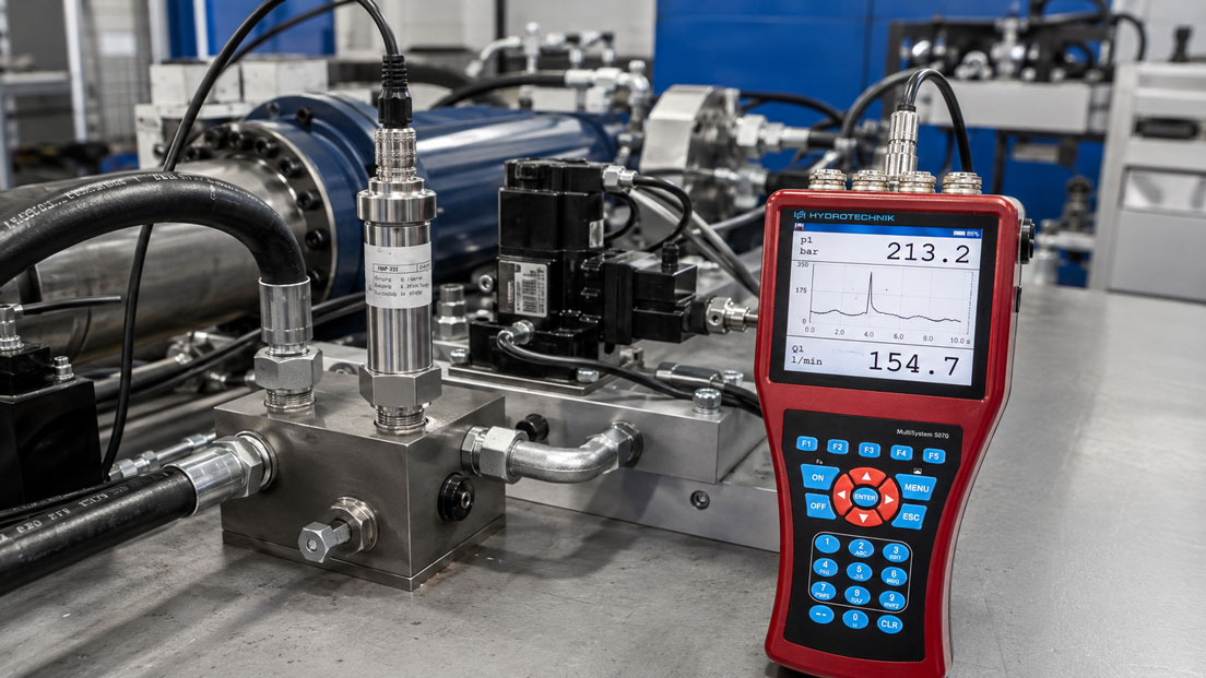
Rare pressure spikes are among the most difficult faults to diagnose in hydraulic systems, test benches and mobile machinery. The system may operate without any noticeable problem for hours, while a brief switching operation, an abruptly closing valve or a mechanical end stop generates a critical pressure surge within just a few milliseconds.
With a conventional pressure logger that stores only one value every few seconds or minutes, such events remain completely invisible. Even a subsequently displayed maximum value provides only limited information if neither the time characteristic nor the operating condition before and after the pressure spike was recorded.
For a reliable diagnosis, the pressure sensor, measuring connection, signal transmission, sampling rate, filtering and trigger function must be considered as one complete measuring chain. A fast logger cannot compensate for a slow sensor. Likewise, a suitable sensor cannot correctly detect a pressure spike if it is attenuated by a long measuring hose, a restrictor or a pressure snubber.
Suitable instruments can be found in the ICS category Pressure Data Loggers. Pressure sensors, connection technology and additional components are grouped under Pressure Measurement Technology.
Table of Contents
- Why are short pressure spikes frequently missed?
- Considering the complete dynamic measuring chain
- Correctly selecting the sampling rate and sampling interval
- Which trigger types are suitable?
- How do pre-trigger and ring-buffer functions work?
- Defining the post-trigger period and recording duration
- Configuring hysteresis and trigger rearming
- Calculating memory requirements and the number of channels
- Selecting the measuring range and pressure reserve
- Checking sensor bandwidth and response time
- Correctly designing the measuring point, hose and adapters
- Correctly assessing filtering and peak detection
- Synchronising timestamps and multiple measuring channels
- Distinguishing between a recording trigger and a safety shutdown
- Recommended configuration procedure
- Practical example: Pressure surge when a valve closes
- Typical errors when recording pressure spikes
- What should be included in the measurement documentation?
- Which products and solutions are suitable?
- Conclusion
- Frequently asked questions
Why are short pressure spikes frequently missed?
A data logger does not store the pressure continuously, but only at defined points in time. Between two samples, the instrument has no information about the actual pressure characteristic.
If only one value is stored every ten seconds, a pressure spike may occur and disappear completely between two measuring points. The resulting diagram then shows an apparently stable pressure characteristic.
This problem occurs in applications including:
- rapidly closing directional-control or seat valves,
- abrupt deceleration of hydraulic cylinders,
- mechanical end stops,
- load changes on pumps and hydraulic motors,
- opening or closing of check valves,
- switching of pressure-relief valves,
- switching between pump stages,
- cavitation followed by the collapse of vapour bubbles,
- hydraulic accumulators with an incorrect pre-charge pressure,
- hose and pipe resonances.
A rare spike may be decisive for the service life of hoses, seals, valves, sensors and housings, even though the normal operating pressure remains entirely within the permissible limits.
Considering the complete dynamic measuring chain
The usable speed of a pressure measurement is limited by the slowest element in the measuring chain.
The measuring chain typically consists of:
Pressure point → connection bore → adapter or test coupling → hose → pressure sensor → sensor signal → measuring-instrument input → input filter → data logger → evaluation software
A high logger sampling rate alone is not sufficient. Examples:
- A logger samples at 10 kHz, but the sensor requires 20 ms to settle.
- The sensor is fast, but a long, flexible measuring hose attenuates the pressure spike.
- The sensor and logger are fast, but a 50 Hz low-pass filter is activated in the measuring instrument.
- The measuring chain is dynamically suitable, but the selected measuring range is exceeded and the signal is clipped.
Before a measurement, the dynamic characteristics of every element must therefore be checked against the expected event duration.
Correctly selecting the sampling rate and sampling interval
The sampling rate specifies how many measured values are recorded per second. The corresponding sampling interval is:
Δt = 1 / fs
Here, fs is the sampling rate.
| Sampling rate | Sampling interval | Assessment for fast pressure spikes |
|---|---|---|
| 1 Hz | 1 s | Suitable only for slow pressure characteristics |
| 10 Hz | 100 ms | Short switching peaks are usually missed |
| 100 Hz | 10 ms | Suitable for slower pressure surges, but not for events in the lower millisecond range |
| 1 kHz | 1 ms | Records a 5 ms spike with approximately five measuring points |
| 10 kHz | 0.1 ms | Records a 5 ms spike with approximately 50 measuring points |
A small number of measuring points may be sufficient simply to detect an event. However, significantly more measuring points should be available across the shortest relevant event duration if the waveform, rise time, overshoot and decay are to be assessed.
As a practical planning rule, at least five to ten measuring points across the shortest signal change of interest are often useful. For an expected rise time of 2 ms, a sampling rate of several kilohertz should therefore be selected rather than only a few hundred hertz.
Nevertheless, a very high sampling rate is not automatically optimal. It increases:
- memory requirements,
- the quantity of transmitted data,
- the evaluation effort,
- sensitivity to high-frequency noise,
- where applicable, restrictions on the number of channels that can be recorded simultaneously.
The sampling rate should therefore be set as high as necessary, but not to the maximum without a technical reason.
Which trigger types are suitable?
With event-triggered recording, the logger does not store data indefinitely at the highest speed. Instead, it waits for a defined event and then saves the relevant time window.
Rising-edge level trigger
Recording is triggered as soon as the pressure crosses a threshold from below to above. This setting is suitable for positive pressure spikes.
Falling-edge level trigger
The trigger responds when the pressure falls below a defined value. This can be used to investigate pressure drops, pump failures or cavitation.
Window trigger
The logger responds as soon as the pressure leaves a permissible range. This allows both pressure spikes and pressure drops to be recorded during the same measurement.
External digital trigger
A switching signal from a valve, controller, limit switch or PLC starts the recording. This is useful when the triggering machine condition is known and the pressure response is to be evaluated in relation to it.
Logical combination of several conditions
With suitable measuring systems, several conditions can be combined using AND or OR logic. Examples:
- pressure above the threshold and valve signal active,
- pressure above the maximum value or below the minimum value,
- pressure spike only at a specific motor speed,
- trigger only during a defined test cycle.
The trigger value should be above normal operating fluctuations but below the suspected critical spike. If it is set too low, numerous unusable event files will be generated. If it is set too high, the event being investigated may not be recorded.
How do pre-trigger and ring-buffer functions work?
The pre-trigger function saves measured values that were recorded before the actual trigger event. This makes it possible to identify what caused the pressure spike.
While the logger is waiting for an event, it continuously writes measured values to a ring buffer. Once the buffer is full, the oldest values are overwritten. As soon as the trigger condition is fulfilled, the defined time period before the event is permanently saved.
Without a pre-trigger, the saved curve begins only when the threshold is crossed. Important information is then missing, including:
- the pressure level immediately before the event,
- a gradual pressure increase before the spike,
- the pump or valve switching condition,
- preceding oscillations,
- the initial position of a cylinder,
- flow rate and speed before loading.
The required pre-trigger period depends on the system. A few hundred milliseconds may be sufficient for a fast valve-switching operation. Several seconds may be required for a machine with a multi-stage operating cycle.
Example:
- total recording duration: 4 s,
- pre-trigger: 1 s,
- trigger point: 25% of the file,
- post-trigger: 3 s.
This records both the system condition before the threshold is exceeded and the subsequent pressure stabilisation.
Defining the post-trigger period and recording duration
The post-trigger setting determines how long recording continues after the event. It must be long enough to capture the complete decay and any subsequent events.
An excessively short post-trigger may cut off information including:
- a second or third pressure spike,
- subsequent oscillation of the line,
- opening of a pressure-relief valve,
- a pressure drop following an overpressure spike,
- the response of an accumulator,
- the return to normal operating pressure.
An excessively long period, by contrast, uses unnecessary memory and makes evaluation more difficult. If the cause of the fault is unknown, a longer follow-up period is initially advisable. Once the first successful recording has been obtained, the time window can be shortened selectively.
Configuring hysteresis and trigger rearming
If the pressure is close to the trigger value, the signal may cross the threshold repeatedly in both directions. Without hysteresis, this can generate numerous individual triggers or uncontrolled retriggering.
Example:
- rising-edge trigger value: 280 bar,
- hysteresis: 10 bar,
- trigger is rearmed only after the pressure falls below 270 bar.
The hysteresis should be greater than the normal signal noise. However, it must not be so large that a subsequent relevant event is not detected again.
A dead time or lockout period after each event may also be useful. It prevents one damped oscillation from being stored as numerous separate events.
Calculating memory requirements and the number of channels
The number of stored measured values can be calculated in simplified form as:
N = fs × t × n
Where:
- N: number of measured values,
- fs: sampling rate per channel,
- t: recording duration,
- n: number of recorded channels.
Example:
- four measuring channels,
- 10,000 measured values per second and channel,
- 30 s recording duration.
This gives:
N = 10,000 × 30 × 4 = 1,200,000 measured values
Assuming four bytes per measured value, this results in at least 4.8 MB of raw measurement data. Timestamps, channel information and file management increase the actual memory requirement further.
When several channels are used, it must be checked whether the specified maximum sampling rate is available:
- for every channel simultaneously,
- only for individual high-speed channels, or
- as a total sampling rate shared across all channels.
These specifications vary depending on the measuring instrument.
Selecting the measuring range and pressure reserve
The pressure sensor must be able to record the highest pressure spike that actually occurs within its measuring range. If the measuring range is exceeded, the output signal reaches its maximum value. The curve is clipped and the true peak pressure remains unknown.
The overload or burst pressure of a sensor is not an additional measuring range. It only specifies a load limit within which the sensor should not, or should not immediately, suffer mechanical damage.
For unknown pressure spikes, it is advisable to begin with a sensor offering a sufficient measuring-range reserve. After the first measurement campaign, a smaller measuring range may be used where appropriate to improve resolution and accuracy within the normal operating range.
The following must be considered when selecting the range:
- normal operating pressure,
- set pressure of pressure-relief valves,
- maximum permissible system pressure,
- suspected magnitude of the transients,
- permissible sensor overload pressure,
- resolution of the complete measuring chain,
- possible pressure spikes in both directions.
A 250 bar sensor is not suitable if short-term spikes above 300 bar are suspected in a system operating at 210 bar. In this case, a sufficiently dynamic 400 or 600 bar sensor should initially be considered, for example.
Checking sensor bandwidth and response time
The accuracy of a pressure sensor does not automatically describe its dynamic behaviour. A highly accurate process pressure transmitter may be too slow for millisecond events because of internal filtering or electronic damping.
Important sensor specifications include:
- response time,
- bandwidth or cut-off frequency,
- internal sampling rate,
- adjustable damping,
- output signal and transmission rate,
- overload resistance,
- pressure-cycle resistance.
A logger operating at 10 kHz does not provide ten kilohertz of usable pressure information if the sensor has a response time of 50 ms, for example.
The signal type must also be considered. An analogue 4–20 mA signal can generally transmit dynamic changes, but the actual speed depends on the sensor, current loop, input circuit and filtering.
For digitally transmitted sensor values, the update rate, bus cycle and internal sensor processing limit the usable time resolution.
Correctly designing the measuring point, hose and adapters
Pressure spikes are local dynamic events. The pressure characteristic directly at the valve may differ significantly from a measurement taken several metres away.
The measuring point should be positioned as close as possible to the suspected cause or the component at risk, for example:
- directly on the valve manifold,
- at the cylinder connection,
- at the pump outlet,
- upstream and downstream of a check valve,
- upstream and downstream of a restrictor,
- at the inlet of a hydraulic accumulator.
For fast measurements, the hydraulic connection should be short, free from trapped gas and sufficiently rigid. Long hoses can:
- attenuate pressure spikes,
- cause a time delay,
- generate their own resonances,
- cause additional distortion because of trapped air.
Pressure snubbers, capillary restrictors or heavily damped gauge valves must not remain unnoticed in the measuring line. Although they protect an indicating instrument against pulsations, they prevent the detection of the fast pressure spike being investigated.
Nevertheless, the sensor should not be mounted without protection at a point exposed to severe vibration. Where applicable, a very short, suitable high-pressure connection may be mechanically preferable to rigid installation directly on a vibrating assembly.
Correctly assessing filtering and peak detection
Filters reduce noise and unwanted high-frequency signal components. At the same time, however, they change the shape of a fast pressure spike.
A low-pass filter with an excessively low setting can:
- reduce the measured peak value,
- increase the rise time,
- smooth out short events completely,
- combine two separate spikes into one broad curve.
The filter setting must therefore be documented and matched to the measurement objective. For initial troubleshooting, a dynamic or minimally damped setting is often useful. Interfering frequency components can then be considered additionally during the evaluation.
The highest stored individual value is not necessarily the physically highest pressure. If the spike occurs between two sampling points, it may be underestimated.
A hardware peak detector or a fast internal maximum-value memory can additionally record short spikes. However, it does not replace the complete time characteristic when the cause and dynamics are to be investigated.
Synchronising timestamps and multiple measuring channels
A single pressure channel is often insufficient for root-cause analysis. Useful additional variables include:
- a second pressure upstream or downstream of a valve,
- flow rate,
- cylinder speed or displacement,
- pump speed,
- valve-control signal,
- motor current,
- temperature,
- a digital machine event.
The channels must be recorded with sufficient time synchronisation. Only then can it be determined whether, for example, the valve closed first, the flow rate decelerated first or the pressure increased first.
If several independent loggers are used, a manually configured clock timestamp is usually insufficient for millisecond events. A common external trigger or verified device-to-device synchronisation is required.
Distinguishing between a recording trigger and a safety shutdown
A trigger in the data logger is used to record measured values. It is not automatically a safety-related pressure-limiting function.
The system continues to require suitable protective measures such as:
- pressure-relief valves,
- pressure-resistant components,
- safe control functions,
- mechanical protective devices,
- where applicable, certified pressure switches or safety circuits.
The recording trigger can intentionally be set below a critical shutdown limit. This allows abnormal events to be documented before the actual protective function intervenes.
Changing the trigger value, filter or measuring range must never result in existing machine safety limits being modified or bypassed.
Recommended configuration procedure
- Define the fault pattern: Determine the suspected cause, operating condition and expected event duration.
- Select the measuring point: Install the sensor as close as possible to the relevant valve or load.
- Define the pressure range: Consider the normal pressure, suspected spike and sufficient measuring reserve.
- Check the dynamics: Assess the response time and bandwidth of the sensor, input and measuring connection.
- Define the channels: Record the pressure and relevant control, flow, displacement or speed signals.
- Select the sampling rate: Provide several measuring points across the shortest expected signal change.
- Configure the filter: Do not activate unnecessarily strong damping for the initial measurement.
- Record the baseline characteristic: Determine the normal operating pressure and signal noise without a trigger.
- Set the trigger value: Above normal fluctuations, but below the spike being investigated.
- Select the edge: Rising edge for overpressure, falling edge for a pressure drop.
- Configure the hysteresis: Greater than the signal noise, but smaller than relevant differences between events.
- Define the pre-trigger: Store sufficient time to record the system condition before the spike.
- Define the post-trigger: Fully record the decay, subsequent impulses and system response.
- Perform a test event: Check the trigger function and file content under controlled conditions.
- Check signal clipping: Ensure that the sensor and input do not reach the end of their measuring range.
- Repeat the measurement: Examine several events for reproducibility.
- Export the data: Save the raw data, instrument configuration and event files together.
Practical example: Pressure surge when a valve closes
Damage occurs irregularly on a high-pressure hose in a hydraulic test bench. The normal operating pressure is between 190 and 250 bar. A previously used logger stores one measured value per second and indicates a maximum pressure of 251 bar.
The following measuring chain is configured for the dynamic investigation:
- fast pressure sensor with a measuring range from 0 to 600 bar,
- short measuring connection directly on the valve manifold,
- data logger with a 10 kHz sampling rate,
- additional digital channel for the valve-switching signal.
The recording is configured as follows:
- trigger channel: pressure,
- trigger type: rising edge,
- trigger value: 280 bar,
- hysteresis: 15 bar,
- pre-trigger: 0.5 s,
- post-trigger: 2.5 s,
- sampling rate: 10 kHz.
The recording shows that approximately 4 ms after the valve closes, a pressure spike of 342 bar occurs and lasts for 7 ms. The pressure then oscillates between 220 and 290 bar for approximately 120 ms.
At a sampling rate of one measured value per second, the complete event occurred between two stored measuring points and was therefore not visible.
After adjusting the valve ramp and checking the hydraulic accumulator, the measurement is repeated under identical conditions. The highest reproducible spike is then 274 bar.
The example demonstrates that not only the maximum value, but also the time relationship between the valve signal, pressure rise and subsequent oscillation is decisive for fault analysis.
Typical errors when recording pressure spikes
| Error | Possible consequence | Suitable corrective action |
|---|---|---|
| Sampling rate too low | A short pressure spike is missed or significantly underestimated | Match the sampling rate to the shortest expected event duration |
| Only the maximum value is stored without the time characteristic | The cause and sequence of events remain unknown | Use trigger recording with pre-trigger and post-trigger |
| No pre-trigger configured | The system condition before the spike is missing | Configure a sufficiently long ring-buffer lead time |
| Trigger value too low | Numerous normal operating events activate the trigger | Measure the normal range first and set the trigger above it |
| Trigger value too high | The pressure spike being investigated is not stored | Set the trigger sufficiently below the suspected spike |
| No hysteresis | Multiple triggering caused by signal noise or subsequent oscillation | Define a suitable reset threshold |
| Measuring range too small | The signal is clipped at its maximum value | Use a sensor with a sufficient measuring-range reserve |
| Overload range interpreted as the measuring range | The peak value remains unknown and the sensor may be damaged | Assess the nominal measuring range and overload limit separately |
| Slow process sensor used | The spike is dynamically smoothed | Check the sensor bandwidth and response time |
| Long, flexible measuring hose | Attenuation, delay or resonance | Use the shortest technically safe measuring connection |
| Pressure snubber installed upstream of the sensor | The pressure surge being investigated is filtered out | Remove the damping element for the dynamic measurement where permissible |
| 50 Hz filter activated for a millisecond event | The peak value and rise time are distorted | Select and document a filter suitable for the measurement objective |
| Several loggers compared only by their internal clocks | The sequence of events in the millisecond range is unclear | Use a common trigger or verified synchronisation |
| Logger trigger used as a safety device | The protective function of the system is not guaranteed | Design diagnostic recording and safety shutdown separately |
What should be included in the measurement documentation?
Traceable documentation should include at least:
- the system, machine and measurement objective,
- the date and responsible person,
- the operating condition during the measurement,
- the position of every pressure sensor,
- the sensor manufacturer, type and serial number,
- the pressure measuring range and overload limit,
- the calibration status,
- the response time or bandwidth,
- the type and length of the hydraulic measuring connection,
- the measuring instrument and input channel used,
- the sampling rate for each channel,
- active input and software filters,
- the trigger channel and trigger type,
- the trigger value, edge and hysteresis,
- the pre-trigger and post-trigger time,
- the number of recorded events,
- maximum and minimum values,
- the rise time and event duration,
- the time relationship to valve, speed or control signals,
- the raw data and export format,
- changes made to the system and the subsequent comparative measurement.
A screenshot alone is usually insufficient for subsequent re-evaluation. The raw data and complete instrument configuration should be stored together with the test report.
Which products and solutions are suitable?
MultiSystem 5070
The MultiSystem 5070 is a portable multi-channel measuring system for pressure, temperature, flow and analogue, digital and CAN-based signals.
The analogue inputs support sampling rates of up to 10 kHz. Up to six million measured values can be stored per measurement series. Several channels can be used as start or stop triggers and combined logically.
The instrument is therefore suitable for event-triggered pressure measurements on mobile machinery, hydraulic systems and test benches.
MultiControl 8050
The MultiControl 8050 is a measuring box for mobile applications and test benches. It has two high-speed analogue inputs with sampling rates of up to 10 kHz, as well as additional analogue, digital, frequency and CAN inputs.
Up to six million measured values can be stored per measurement series. Operation and evaluation are performed using a connected PC with the associated Hydrotechnik software.
This version is particularly suitable for permanently installed test benches on which several variables must be evaluated synchronously in relation to a pressure spike.
MultiHandy 2025
The MultiHandy 2025 is designed for portable service and diagnostic tasks. Measurement peaks can be detected, assessed and documented for test reports.
The instrument is available in preconfigured sets with pressure sensors covering different measuring ranges. Before using it for very short millisecond events, the specific sampling rate, sensor dynamics and required event duration must be assessed together.
IMP320 fast precision pressure sensor
The IMP320 is designed for fast pressure characteristics, pressure steps and pressure surges.
The sensor has an internal sampling rate of 10 kHz and a response time of no more than 0.5 ms. Measuring ranges are available from low pressures up to 600 bar.
In a correspondingly fast measuring chain, the sensor can therefore also record short hydraulic pressure events.
HySense PR509
The HySense PR509 is a piezoresistive pressure sensor with a 4–20 mA output, short response time and automatic sensor recognition for suitable Hydrotechnik measuring instruments.
It is suitable for portable hydraulic measurements, provided that the measuring range, sensor dynamics and logger configuration are appropriate for the duration of the event being investigated.
MultiXtend Trigger
The MultiXtend Trigger distributes a common trigger signal to several compatible Hydrotechnik measuring systems.
With a suitable combination of instruments, several measuring devices can therefore be triggered simultaneously and extensive multi-channel measurements can subsequently be evaluated together.
ICS Schneider Messtechnik provides support in selecting the pressure sensor, measuring range, sampling rate, trigger logic, connection cable and measuring instrument, as well as in assembling complete measuring cases for hydraulics, test benches and mobile machinery.
Conclusion
Rare pressure spikes cannot be reliably detected using slow interval recordings. An event lasting only a few milliseconds may occur entirely between two stored measuring values.
The sampling rate must be appropriate for the shortest relevant signal change. Several measuring points are required across the rise, peak and decay to assess the waveform.
A level trigger limits the quantity of data to relevant events. The pre-trigger shows which system condition caused the pressure spike, while the post-trigger documents the subsequent oscillation and return to normal operation.
Hysteresis and a lockout period prevent multiple triggers caused by signal noise. The trigger value and reset threshold must be defined on the basis of a previously measured normal operating range.
The usable frequency range is determined by the complete measuring chain. A fast logger cannot compensate for either a slow pressure sensor or a heavily damping measuring hose.
The measuring range, overload resistance and resolution must be assessed separately. Once the end of the measuring range is reached, the actual magnitude of the pressure spike can no longer be determined.
For a reliable diagnosis, pressure, valve signal, flow rate, speed or displacement should be recorded synchronously. Only their time relationship enables an unambiguous root-cause analysis.
Frequently asked questions about event-triggered recording of pressure spikes
Why does my pressure logger not show the suspected pressure spike?
The sampling rate is frequently too low, or the spike is attenuated by the sensor, filter, hose or restrictor. An unsuitable measuring point can also conceal the event.
What sampling rate do I need for a 5 ms pressure spike?
At 1 kHz, approximately five measuring points are generated across 5 ms. A higher sampling rate, such as several kilohertz, is advisable for a more accurate assessment of the waveform.
What does pre-trigger mean?
The logger continuously stores values in a ring buffer. When the trigger is activated, the measured values from the defined period before the trigger are also saved permanently.
How large should the pre-trigger portion be?
It must record the relevant system condition before the event. Depending on the machine, this may require a few hundred milliseconds or several seconds.
Why does the trigger require hysteresis?
Without hysteresis, a noisy or oscillating signal can cross the trigger value repeatedly in both directions and therefore retrigger several times.
Where should the trigger value be set?
Above the highest normal operating fluctuation, but sufficiently below the expected critical pressure spike. The normal pressure range should therefore be measured first.
Can I always use the maximum sampling rate?
This is not always technically useful. A higher rate increases memory requirements and sensitivity to noise. It should be appropriate for the event duration, sensor bandwidth and number of channels.
Is a highly accurate sensor sufficient?
No. The response time, bandwidth, internal filter and pressure-cycle resistance must also be suitable for the fast measurement task.
Why does a long measuring hose attenuate pressure spikes?
The hose volume and flexible hose wall change the dynamic transmission behaviour. Trapped air increases the attenuation further.
May a pressure snubber be installed upstream of the sensor?
This is usually unsuitable for targeted pressure-spike measurements because the pressure snubber attenuates the fast pressure change being investigated. However, the specific design must be assessed on the basis of the system and the permissible sensor load.
What does a pressure curve clipped at the top mean?
The sensor or measuring input has reached the end of its measuring range. The actual peak pressure is at least at this level, but can no longer be determined.
Can the data logger replace a pressure-limiting function?
No. The logger is used for diagnosis and documentation. It does not replace a safety-related pressure-limiting function or any other required protective function.