


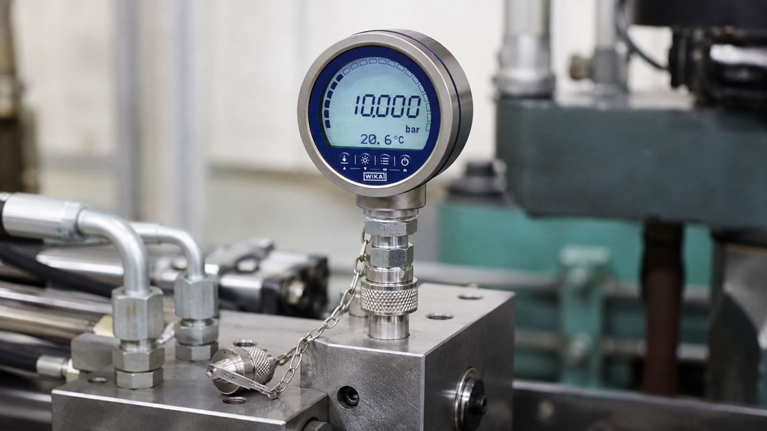
An existing test coupling looks like MINIMESS at first glance. However, the test hose cannot be screwed on. Another hose initially appears to fit but becomes difficult to turn after only a few threads. Is the process connection thread simply incorrect, or is it a different MINIMESS series?
This is exactly where incorrect orders frequently occur in hydraulic service. MINIMESS 1215, 1615, 1620 and 1604 all follow the same basic principle, but they are not freely interchangeable on the coupling side.
The decisive factors include the MINIMESS series, coupling thread, nominal size, maximum permissible operating pressure, process connection thread, sealing type and seal material.
A particularly common mistake is to confuse the coupling thread with the process connection thread. A MINIMESS 1620 test point can, for example, have a metric M12 × 1.5 process connection. The coupling side nevertheless remains MINIMESS 1620 with M16 × 2.
Original MINIMESS couplings, hoses and accessories can be found under MINIMESS Couplings and Hoses. Particularly compact versions are grouped under MINIMESS Couplings Series 1215.
Table of Contents
- How does a MINIMESS test point work?
- Direct comparison of 1215, 1615, 1620 and 1604
- Distinguishing between the coupling side and process connection side
- When is MINIMESS 1620 the correct choice?
- When is MINIMESS 1615 required?
- When is MINIMESS 1215 useful?
- When should MINIMESS 1604 be used?
- Checking the operating pressure correctly
- Valve actuation and mating coupling must match
- Considering seal material and medium
- Why the protective cap is important
- Identifying an existing MINIMESS test point
- Avoiding adapters and mixed installations
- Selecting the correct MINIMESS hose
- Which series is suitable for a new system?
- Practical example from hydraulic service
- Typical ordering mistakes
- Documenting test points clearly
- Which products and solutions are suitable?
- Conclusion
- Frequently asked questions
How does a MINIMESS test point work?
A MINIMESS test point provides compact access to a fluid power system. It can be used, for example, for:
- pressure measurements,
- connecting pressure sensors,
- diagnostic measurements,
- sampling,
- filling,
- venting,
- draining.
Inside the test point is a mechanically actuated check valve. Without a connected test hose, the test point remains closed.
When the correct MINIMESS mating coupling is screwed on, it actuates the valve mechanism. This opens the connection between the system and the measuring line.
For applications designed for this purpose, this allows a measuring instrument to be connected while the system is pressurised without having to install a conventional shut-off valve for every measurement.
However, this valve technology is also one reason why similar-looking couplings must not be combined arbitrarily.
For a functional connection, all of the following must match:
- coupling series,
- thread on the coupling side,
- sealing geometry,
- actuation mechanism of the check valve,
- permissible operating pressure,
- hose and mating coupling.
Direct comparison of 1215, 1615, 1620 and 1604
| MINIMESS Series | Coupling Side | Nominal Size | Max. Operating Pressure of the Series | Typical Application |
|---|---|---|---|---|
| 1620 | M16 × 2 | DN2 | up to 630 bar | Standard test points for pressure measurement, diagnostics, sampling, filling and venting |
| 1615 | M16 × 1.5 | DN2 | up to 630 bar | Alternative M16 coupling series, particularly for existing 1615 systems |
| 1215 | small series-specific coupling thread | DN2 | up to 630 bar | Particularly compact test points where installation space is limited |
| 1604 | larger series-specific coupling system | DN4 | up to 400 bar | Filling and draining with a larger free cross-section |
The pressure ratings in this overview are the maximum values for the respective series. The actual permissible operating pressure of a specific product may be lower depending on the process connection thread, sealing type, material, seal and design.
The specific product and its technical data sheet are therefore always decisive when placing an order.
Distinguishing between the coupling side and process connection side
Two sides of a MINIMESS test point must always be considered separately.
1. Coupling side
This is the side to which the MINIMESS hose or mating coupling is connected.
This side determines the actual MINIMESS series.
Examples:
- MINIMESS 1620: M16 × 2,
- MINIMESS 1615: M16 × 1.5,
- MINIMESS 1215: compact 1215 coupling geometry,
- MINIMESS 1604: larger 1604 coupling geometry with DN4.
2. Process connection side
This side connects the test point to the machine, pipework, hydraulic block or an adapter.
Depending on the version, different connection threads are available, for example:
- M10 × 1,
- M12 × 1.5,
- M14 × 1.5,
- G 1/8,
- G 1/4,
- UNF connections,
- NPT connections.
Not every combination is available in every series.
Particularly important:
An M12 × 1.5 thread on the process connection side does not mean that the test point is MINIMESS 1215.
A MINIMESS 1620 test point can also be screwed into a hydraulic block using an M12 × 1.5 process connection while its measuring side continues to use the 1620 M16 × 2 coupling system.
For replacement orders, both connections must therefore be specified separately.
When is MINIMESS 1620 the correct choice?
MINIMESS 1620 is the most commonly used series for conventional hydraulic measurement and diagnostic points.
The coupling side uses:
M16 × 2
The nominal size is:
DN2
The series is available for operating pressures up to a maximum of 630 bar and is used, among other applications, for:
- mobile hydraulics,
- construction machinery,
- machine tools,
- hydraulic power units,
- test benches,
- industrial hydraulics,
- condition monitoring.
An important advantage is the widespread use of the series. Many measuring hoses, test kits, pressure sensor adapters and diagnostic instruments are supplied as standard with 1620 connections.
The 1620 series is also designed in accordance with ISO 15171-2.
For a new standard hydraulic system, 1620 is therefore often the natural starting point unless there are specific requirements to the contrary.
When is MINIMESS 1615 required?
MINIMESS 1615 looks very similar to the 1620 series.
The decisive difference is the coupling thread:
MINIMESS 1615 = M16 × 1.5
compared with:
MINIMESS 1620 = M16 × 2
Both systems therefore have a nominal thread diameter of approximately 16 mm but differ in thread pitch.
This is precisely why there is a high risk of confusion.
An M16 × 2 hose connection must not be forced onto an M16 × 1.5 test point.
After only a few turns, the connection may become difficult to screw together. Further tightening can:
- damage the thread,
- cause the coupling to become misaligned,
- damage the sealing geometry,
- create an unsafe connection.
Like 1620, MINIMESS 1615 has a nominal size of DN2 and suitable versions are available for pressures up to 630 bar.
The series is particularly relevant when existing machines are already equipped with 1615 test points and this system is to be continued.
When is MINIMESS 1215 useful?
MINIMESS 1215 is the compact version among the conventional MINIMESS test points.
It features:
- DN2,
- a particularly small coupling side,
- a compact design,
- operating pressures up to 630 bar depending on the version.
This makes 1215 particularly suitable for:
- small hydraulic blocks,
- valve blocks with narrow connection spacing,
- mobile machinery,
- test points with limited installation space.
When identifying the series, the designation 1215 alone should not be interpreted as an ordinary M12 × 1.5 process thread.
The current Hydrotechnik system uses a series-specific compact thread geometry on the coupling side. At the same time, metric threads such as M12 × 1.5 may also be used on the process connection side of the test coupling.
These two connections have completely different functions.
When should MINIMESS 1604 be used?
MINIMESS 1604 differs more significantly from the three DN2 series.
Its most important feature is:
Nominal size DN4
The larger free cross-section is particularly useful for applications in which not only a pressure signal has to be transmitted but a greater volume flow through the test point is required.
Typical applications include:
- faster filling,
- draining,
- venting,
- service work requiring a higher flow rate.
However, the larger nominal size must not be confused with a higher pressure rating.
The 1604 series is designed for operating pressures up to a maximum of:
400 bar
.
For pure pressure measurements in typical high-pressure hydraulic applications, a DN2 series is therefore often more suitable.
Checking the operating pressure correctly
One of the most dangerous assumptions is:
“MINIMESS is always suitable for 630 bar.”
This is not correct.
The 1215, 1615 and 1620 series can achieve operating pressures of up to 630 bar in suitable versions. However, this does not mean that every individual test point with every available process connection is automatically approved for 630 bar.
The actual permissible operating pressure can be influenced by:
- process connection thread,
- thread size,
- sealing type,
- material,
- seal material,
- temperature,
- medium.
The pressure rating of the specific part number selected must therefore always be checked.
For MINIMESS 1604, it must additionally be noted that the series is fundamentally designed for a maximum of 400 bar.
Valve actuation and mating coupling must match
The external thread is only one part of the connection.
When the correct mating coupling is screwed on, the internal check valve of the test point is mechanically opened at the same time.
For this to function reliably, the following must match:
- thread,
- screw-in depth,
- actuation travel,
- sealing point,
- mating coupling
.
A coupling that appears to screw on can therefore still be unsuitable.
An incorrect combination may, for example:
- fail to open the valve at all,
- open the valve only partially,
- prevent the seal from seating correctly,
- cause leakage,
- damage the thread.
Particularly at high hydraulic pressures, compatibility must therefore never be tested by forcibly screwing components together.
Considering seal material and medium
In addition to the mechanical series, the seal material must be suitable for the medium used and the operating temperature.
Depending on the version, MINIMESS test points are available with different elastomers.
These include, for example:
- NBR,
- FKM,
- EPDM in suitable versions.
The correct selection depends on the medium.
Typical applications can include:
- mineral-oil hydraulics,
- water-glycol mixtures,
- fire-resistant hydraulic fluids,
- other industrial fluids.
The mechanical fit of the coupling alone therefore does not confirm media compatibility.
For other fluids, the O-ring and metallic surfaces in particular must be checked for chemical resistance.
Why the protective cap is important
The protective cap should be correctly reinstalled after every measurement.
It protects the coupling side particularly against:
- dust,
- metal chips,
- dirt,
- moisture,
- mechanical damage.
Even small dirt particles can enter the sealing or valve area the next time the hose is connected.
This is particularly critical because connecting the hose opens access to the hydraulic system.
Before every measurement, the following procedure should therefore be followed:
- remove the protective cap,
- check the coupling area for contamination,
- clean it if necessary in accordance with operational requirements,
- only then connect the test hose.
The protective caps should also be selected to match the MINIMESS series used.
Identifying an existing MINIMESS test point
On older machines, parts lists or clear information about the test coupling are often missing.
In this case, identification should be carried out systematically.
- Check manufacturer and markings: First evaluate existing part numbers, markings or documentation.
- Inspect the coupling side: Do not begin by assessing the process connection thread to the hydraulic block.
- Compare physical size: 1215 is particularly compact, while 1604 has the larger DN4 system cross-section.
- Determine the thread diameter: Both 1615 and 1620 use an M16 coupling side.
- Check the thread pitch: 1615 uses M16 × 1.5, while 1620 uses M16 × 2.
- Check the existing hose: Verify the designation and part number of the mating coupling.
- Record the process connection side separately: Only then determine the process thread and sealing type.
- Document pressure and medium: These are required to select the specific version.
With an unknown pressurised test point, different couplings should never be tried by screwing them on experimentally to determine which series fits.
Identification should be carried out safely using documentation, dimensions and clear connection characteristics.
Avoiding adapters and mixed installations
In a machine with numerous test points, several MINIMESS series should preferably not be mixed without a technical reason.
Such a mixed installation leads in the long term to:
- multiple required test hoses,
- more spare parts,
- a higher risk of confusion,
- additional adapters,
- longer service times.
For a new system, it is therefore useful to standardise on one coupling series wherever possible.
Adapters may nevertheless be required during service, for example when one test kit is used on machines from different generations.
Only defined transition adapters designed for the two relevant MINIMESS systems and the required pressure should be used for this purpose.
Improvised thread reducers are not a substitute for such a system adapter.
Every additional adapter also introduces:
- an additional sealing point,
- additional internal volume,
- additional potential leakage points,
- greater mechanical loading
into the measuring chain.
For regularly used test points, a hose with a directly matching mating coupling is therefore normally the better solution.
Selecting the correct MINIMESS hose
The correct microbore hose must be selected for the test point.
Depending on the version, MINIMESS hoses are available in DN2 and DN4, among other sizes.
At least the following must be checked during selection:
- MINIMESS series at the test point,
- connection at the measuring instrument,
- nominal size,
- maximum operating pressure,
- hose length,
- temperature range,
- medium,
- seal materials.
A typical pressure measurement hose may, for example, have the following configuration:
MINIMESS 1620 → DN2 hose → G 1/4 to the pressure gauge
or:
MINIMESS 1620 → DN2 hose → sensor adapter
The measuring instrument connection on the opposite side of the hose must therefore be defined independently of the MINIMESS series.
The same rule applies here:
A G 1/4 connection on the pressure gauge provides no information about whether the system side is 1215, 1615, 1620 or 1604.
Which series is suitable for a new system?
For a new system, the selection can be simplified according to the application.
| Requirement | Typical Selection | Reason |
|---|---|---|
| Standard pressure test point in hydraulics | 1620 | Widely used DN2 series with M16 × 2 and reference to ISO 15171-2 |
| Existing system uses M16 × 1.5 | 1615 | Compatibility with existing 1615 hoses and test points |
| Very limited installation space | 1215 | Compact DN2 version |
| Faster filling or draining required | 1604 | Larger nominal size DN4 |
| Operating pressure above 400 bar | Check 1604 critically | 1604 series is designed for a maximum of 400 bar |
| New standardised machine family | standardise on one series wherever possible | Reduces spare parts, adapters and operating errors |
The table does not replace verification of the specific part number. In particular, the process connection, pressure, temperature, medium and seal must also be taken into account.
Practical example from hydraulic service
A service technician is required to measure pump pressure on three older hydraulic power units.
On the first unit, the existing test hose fits without difficulty. The mating coupling is M16 × 2 and the test point belongs to the 1620 series.
On the second unit, the test point also has an outside diameter of approximately 16 mm. However, the hose can only be screwed on for a few turns before becoming difficult to turn.
The measurement is stopped and the thread pitch is checked.
The result:
- test hose: M16 × 2 or 1620,
- test point: M16 × 1.5 or 1615.
The visually very similar coupling is therefore not compatible.
The third hydraulic power unit has a noticeably smaller test coupling. The documentation specifies MINIMESS 1215.
Instead of permanently using several adapters in series, suitable hose connections or defined transition solutions for the three existing series are provided for the test kit.
The machine documentation is also updated:
- Power Unit 1: MINIMESS 1620,
- Power Unit 2: MINIMESS 1615,
- Power Unit 3: MINIMESS 1215.
For future maintenance work, the correct hose can therefore be selected before work begins.
Typical ordering mistakes
| Error | Possible Consequence | Suitable Corrective Action |
|---|---|---|
| M12 × 1.5 on the hydraulic block interpreted as MINIMESS 1215 | Wrong coupling series ordered | Determine coupling side and process connection side separately |
| 1615 and 1620 distinguished only by outside diameter | Incorrect thread pitch | Clearly distinguish between M16 × 1.5 and M16 × 2 |
| 1620 hose forced onto a 1615 test point | Thread damage and unsafe connection | Use only the correct mating coupling |
| 630 bar assumed universally for every test point | Permissible operating pressure of an individual version may be exceeded | Check the pressure rating of the specific part number |
| 1604 assumed to withstand higher pressure because of its larger nominal size | Pressure limit is exceeded | Use 1604 only within its permissible operating pressure |
| Seal material not considered | Swelling, embrittlement or leakage | Match the seal to the medium and temperature |
| Protective cap permanently omitted | Contamination of the coupling and valve area | Reinstall the protective cap after measurement |
| Several adapters permanently installed in series | Additional sealing points and an unnecessarily complex arrangement | Use a directly compatible test hose |
| DN2 and DN4 not distinguished | Incorrect hose and flow sizing | Consider the nominal size of the series |
| New machines designed without a uniform standard | Many different hose types and spare parts required | Define a preferred MINIMESS series |
Documenting test points clearly
To prevent a service technician from having to determine which coupling is installed during every maintenance visit, each test point should be documented clearly.
Useful information includes:
- plant identification,
- test point number,
- MINIMESS series,
- coupling connection,
- process connection thread,
- sealing type,
- material,
- seal material,
- permissible operating pressure,
- medium,
- suitable test hose,
- connection of the measuring instrument used.
Example:
| Test Point | Series | Coupling Side | Process Connection | Max. Operating Pressure |
|---|---|---|---|---|
| P01 Pump Outlet | 1620 | M16 × 2 | M12 × 1.5 | according to specific version |
| P02 Filter Inlet | 1615 | M16 × 1.5 | G 1/4 | according to specific version |
| P03 Valve Block | 1215 | 1215 | M10 × 1 | according to specific version |
This documentation is significantly clearer than simply stating “MINIMESS connection available”.
Which products and solutions are suitable?
MINIMESS couplings and hoses
The ICS category MINIMESS Couplings and Hoses includes test points, microbore hoses, adapters and other components for pressure measurement, servicing and condition monitoring.
The most important selection parameters are:
- MINIMESS series,
- process connection,
- operating pressure,
- nominal size,
- material,
- seal,
- medium,
- temperature.
MINIMESS Series 1620
The 1620 series with M16 × 2 and DN2 is the widely used standard solution for numerous hydraulic diagnostic and measurement applications.
It is suitable, among other things, for connecting:
- pressure gauges,
- digital pressure gauges,
- pressure sensors,
- portable hydraulic measuring instruments,
- sampling systems.
Suitable versions are available for operating pressures up to 630 bar.
MINIMESS Series 1615
The 1615 series also has DN2 but uses M16 × 1.5 on the coupling side.
It is therefore particularly relevant for existing systems already based on this coupling geometry.
Its visual similarity to 1620 makes clear identification especially important.
MINIMESS Series 1215
The MINIMESS Couplings Series 1215 provide a compact DN2 test point for applications with restricted installation space.
Depending on the version, different international process connection threads and sealing types are available.
MINIMESS Series 1604
The 1604 series has a nominal size of DN4 and therefore offers a larger free cross-section than the DN2 series.
It is particularly suitable for:
- filling operations,
- draining,
- venting,
- service applications requiring a higher flow rate.
The maximum permissible operating pressure of the series is 400 bar.
MINIMESS hoses
Suitable microbore hoses can be configured according to the existing coupling series and the connection of the measuring instrument.
This allows, for example, a 1620 test point to be connected directly to a:
- pressure gauge,
- pressure sensor,
- hydraulic tester,
- data logger
without creating an unnecessary chain of transition adapters.
ICS Schneider Messtechnik provides support in identifying existing MINIMESS test points and selecting the test point, hose, adapter, pressure gauge and pressure sensor for complete measurement and service connections.
Conclusion
MINIMESS 1215, 1615, 1620 and 1604 follow the same basic principle but are different systems on the coupling side.
The most important rule when selecting a series is therefore:
First determine the MINIMESS coupling series and only then select the process connection thread to the system.
MINIMESS 1620 uses M16 × 2, has DN2 and is the widely used standard series. MINIMESS 1615 also has DN2 but uses M16 × 1.5 and is therefore not equivalent to 1620 despite the similar dimensions.
MINIMESS 1215 provides a particularly compact DN2 test point for restricted installation spaces. MINIMESS 1604, by contrast, has DN4 and is particularly intended for faster filling and draining.
The pressure rating must also be checked separately. Depending on the version, 1215, 1615 and 1620 can be suitable for pressures up to 630 bar, while 1604 is intended for a maximum of 400 bar. Individual connection variants may have lower permissible operating pressures.
A coupling that appears to fit mechanically must never be forced into place. Thread, sealing point and actuation mechanism of the check valve must match exactly.
For new systems, it is advisable to standardise consistently on as few coupling series as possible. This significantly reduces the number of test hoses, adapters, spare parts and operating errors.
Frequently asked questions about MINIMESS 1215, 1615, 1620 and 1604
What is the main difference between MINIMESS 1615 and 1620?
The coupling threads are different. MINIMESS 1615 uses M16 × 1.5, whereas MINIMESS 1620 uses M16 × 2. Both series have DN2 but are not identical on the coupling side.
Is MINIMESS 1215 simply an M12 × 1.5 connection?
No. The series designation must not be confused with the process thread. M12 × 1.5 can, for example, also be used on the process connection side of a test point from another MINIMESS series.
Which MINIMESS series is the typical standard version today?
For many conventional hydraulic test points, MINIMESS 1620 with M16 × 2 and DN2 is the widely used standard solution. The series is also referenced to ISO 15171-2.
Why does MINIMESS 1615 exist?
The series provides an alternative M16 coupling geometry with a thread pitch of 1.5 mm. It is particularly relevant for existing systems already equipped with 1615 test points.
When should I use MINIMESS 1215?
Because of its compact design, 1215 is particularly suitable for restricted installation spaces.
What is the advantage of MINIMESS 1604?
The series has DN4 and therefore a larger free cross-section. It is particularly suitable for faster filling, draining and similar service operations.
Is MINIMESS 1604 suitable for higher pressures because it is larger?
No. The larger nominal size does not automatically mean a higher pressure rating. The 1604 series is designed for operating pressures up to a maximum of 400 bar.
Are all MINIMESS 1620 test points suitable for 630 bar?
Not necessarily. 630 bar is the maximum operating pressure of suitable versions of the series. The actual permissible pressure depends on the specific version and particularly on the process connection.
Can I screw a 1620 hose onto a 1615 test point?
No. M16 × 2 and M16 × 1.5 have different thread pitches. Forcing the connection can damage both the thread and the sealing geometry.
Can different MINIMESS series be connected using adapters?
Defined transition solutions are available for service purposes. They must be suitable for the relevant coupling series and the required operating pressure. Improvised thread adapters are unsuitable for this purpose.
How can I identify which series is installed on an older machine?
First check the part number, documentation and coupling side. With 1615 and 1620, the thread pitch is particularly important. The process connection and process thread should be determined separately.
Which information is required for the correct order?
Ideally, the MINIMESS series, coupling side, process connection thread, sealing type, operating pressure, medium, temperature, material and required seal material should be specified. A photograph with dimensions can additionally be helpful for unknown older systems.