


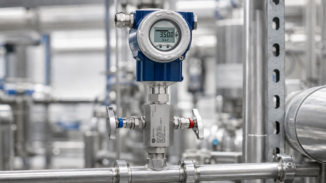
A pressure transmitter needs to be checked while the plant remains in operation. The block valve is closed, pressure is released through the bleed connection and a calibrator is then connected. Nevertheless, a stable zero point cannot be established. Or, even more critically: despite supposedly isolating the transmitter, process pressure is still present at the measuring instrument.
Such situations are often caused not by a defective pressure transmitter, but by the valve position, trapped pressure, a leaking isolation valve or an unsuitable test setup.
A block-and-bleed valve is intended to simplify precisely these tasks: isolating the pressure transmitter from the process, safely depressurising the instrument side and – depending on the design – providing access for zero-point checks, calibration or maintenance.
For this to work reliably, however, the block valve, bleed valve and, where applicable, the test connection must be operated in the correct sequence and in accordance with the process medium and plant work permit.
Products for industrial pressure measuring points can be found under Pressure measurement technology. Valves, manifolds, adapters and other accessories are grouped under Accessories for pressure measuring instruments.
Table of Contents
- What is a block-and-bleed valve?
- Distinguishing between block, bleed and test connections
- Valve positions during normal measurement operation
- Safely isolating the pressure transmitter from the process
- Why trapped pressure is so critical
- Correctly checking the zero point
- Testing a pressure transmitter via the test connection
- Returning the measuring point to service
- Detecting a leaking block valve
- Considering dead volume and trapped medium
- Distinguishing between liquid and gas applications
- Safely discharging bleed medium
- Avoiding pressure surges when opening
- Distinguishing between Block and Bleed and Double Block and Bleed
- Why a differential pressure transmitter requires a different manifold
- Typical operating and measurement errors
- Recommended test procedure
- Practical example from a process plant
- Which products and solutions are suitable?
- Conclusion
- Frequently asked questions
What is a block-and-bleed valve?
A classic block-and-bleed valve for a single pressure measuring point has two valve functions:
- Block: Isolating the pressure transmitter from the process.
- Bleed: Venting or depressurising the volume trapped between the block valve and the measuring instrument.
During normal measurement operation, the pressure transmitter is connected to the process through the open block valve. The bleed valve is closed.
If the transmitter is to be tested or removed, the connection to the process is first interrupted. The pressure still present on the instrument side can then be released in a controlled manner.
This is the key difference between a block-and-bleed valve and a simple isolation valve: after closing a simple isolation valve, the full process pressure may still remain trapped between the valve and the pressure transmitter.
Distinguishing between block, bleed and test connections
When working on a measuring point, it must first be clearly established which function each connection performs.
| Function | Purpose | Typical state during measurement operation |
|---|---|---|
| Block valve | Connects or isolates the transmitter from the process | Open |
| Bleed / vent valve | Depressurises the transmitter side | Closed |
| Test connection | Connection for a calibrator or reference measuring instrument | Closed or plugged |
Not every manifold has a separate test connection. Depending on the design, the bleed connection may also be intended for certain test tasks, or a separate test port may be provided.
Before calibration, the function diagram, markings and manufacturer documentation should therefore always be checked to determine which connection is intended for which purpose.
Valve positions during normal measurement operation
For a classic block-and-bleed measuring point, the basic valve position during normal process operation is simple:
Block valve open – bleed valve closed.
This allows the process pressure to reach the pressure transmitter while preventing process medium from escaping through the bleed connection.
A partially open block valve should not be used as the normal operating position without a technical reason. The valve is primarily intended for isolation and not as an arbitrarily adjustable process restrictor.
The bleed valve must also not accidentally remain open during normal measurement operation. Otherwise, depending on the medium, process medium may continuously escape or the pressure applied to the transmitter may be falsified.
Safely isolating the pressure transmitter from the process
If the pressure transmitter is to be checked or removed, it must first be ensured that no further process pressure can flow towards the instrument.
In a typical block-and-bleed arrangement, the block valve is therefore closed first.
This isolates the transmitter from the process.
However, this does not mean that the area downstream of the block valve is depressurised.
A trapped volume remains between the closed block valve, the manifold, fittings and the sensor diaphragm. This volume may still be at the last applied process pressure.
Only controlled depressurisation via the intended bleed function can release this pressure.
For the specific work, the operating instructions, plant work permit procedure, applicable P&ID and operating instructions for the installed components must always be followed.
Why trapped pressure is so critical
A common operating error is to assume that a closed block valve automatically means that the pressure transmitter is depressurised.
This is incorrect.
If, for example, a measuring point is isolated at 100 bar, approximately 100 bar may still remain trapped on the transmitter side.
If the sensor or an adapter is then loosened, the trapped medium may escape uncontrollably.
This issue is particularly critical with compressed gases because energy is stored in the trapped gas volume.
Residual pressure must also be fully considered with liquids.
Before opening a process connection, it must therefore be clearly ensured that the relevant side has been depressurised in accordance with the specified plant procedure.
Correctly checking the zero point
A common use of the bleed valve is to check the zero point of a gauge pressure transmitter.
The transmitter is first isolated from the process. The instrument side is then depressurised via a suitable and safe route.
For a gauge pressure transmitter, once pressure has been fully equalised with the atmosphere, the sensor should theoretically indicate a value close to 0 bar gauge.
However, there are several typical sources of error:
- The block valve is not completely leak-tight internally.
- The pressure has not been fully released.
- The bleed valve or vent line is blocked.
- A hydrostatic liquid column remains in a liquid-filled line.
- There is an additional elevation difference at the measuring point.
- The transmitter still requires stabilisation time after depressurisation.
A zero-point deviation should only be attributed to the transmitter once it has been ensured that the intended pressure reference is actually present at the sensor.
With an absolute pressure transmitter, however, venting to atmosphere is not a zero-point check. Atmospheric pressure does not correspond to 0 bar absolute for an absolute pressure sensor.
Testing a pressure transmitter via the test connection
A manifold with a test connection enables a comparison or calibration test without completely removing the transmitter from the measuring point.
A typical arrangement consists of:
- process,
- block valve,
- pressure transmitter,
- bleed function, and
- test connection for a pressure calibrator or reference instrument.
Before pressure is applied by the calibrator, it must be clearly ensured that the process is isolated and that the valve positions are correct for the respective test.
The calibrator must not unintentionally work against the live process.
After depressurisation, the test instrument is connected using the intended connection geometry. The test side is then configured so that the generated reference pressure acts only on the transmitter or defined test volume.
Several pressure points can then be applied and the transmitter output signal or display compared with the reference.
With a 4–20 mA transmitter, for example, the electrical output signal can be measured at the same time.
After the test has been completed, the test pressure must first be safely released before the test instrument or adapter is disconnected.
Returning the measuring point to service
The return to normal measurement operation should also be carried out in a controlled manner.
Before reconnecting the instrument to the process, the bleed or test path must be closed.
The block valve is then opened slowly in accordance with the manufacturer’s instructions.
This allows the pressure at the sensor to rise in a controlled manner.
Sudden opening can expose the measuring cell, seals and connected components to unnecessary dynamic loads and pressure surges.
After reconnecting the instrument to the process, at least the following points should be checked:
- Is the bleed valve completely closed?
- Is the test connection correctly sealed?
- Does the transmitter indicate a plausible process pressure?
- Is the output signal plausible?
- Are all opened connections leak-tight?
Detecting a leaking block valve
A closed block valve is also a technical component and, depending on its condition, contamination, wear and process conditions, may leak internally.
A typical indication can be observed during a zero-point check:
The transmitter is isolated and fully depressurised via the bleed valve. The bleed valve is then closed again.
If the pressure on the isolated transmitter side subsequently rises again, this may indicate internal leakage through the block valve.
However, temperature changes, trapped liquid volumes and other connected components must also be taken into account during the assessment.
Such a pressure increase should therefore initially be regarded as a diagnostic indication and does not replace a defined leak test with a specified test procedure and acceptance limit.
Considering dead volume and trapped medium
The space between the isolation valve and the sensor diaphragm is often regarded as a small and insignificant volume.
For testing purposes, however, this dead volume can be relevant.
The larger the volume formed by valve passages, adapters, impulse lines and test connections, the more medium must be displaced or compressed during pressure generation.
This affects, among other things:
- stabilisation time,
- pressure generation using hand pumps,
- sensitivity to small leaks,
- flushing effort, and
- trapped gas bubbles during liquid testing.
A compact measuring point with as few adapters as possible not only reduces potential leak points, but normally also reduces the trapped test volume.
Distinguishing between liquid and gas applications
Venting a gas pressure measuring point and depressurising a liquid-filled measuring line are not completely equivalent.
With gases, the pressure can equalise comparatively quickly after the bleed valve is opened. At the same time, it must be taken into account that compressed gas releases energy when expanding and, depending on the medium, must not be vented uncontrollably.
With liquids, residual volumes or liquid columns may remain.
During hydraulic calibration, trapped gas bubbles are also problematic. Gas is significantly more compressible than a liquid and can therefore lead to:
- slow pressure generation,
- poor stability,
- delayed adjustment, and
- additional stored energy
.
For liquid tests, the test line should therefore be filled as completely as possible with the test medium and vented in accordance with the specified test method.
Safely discharging bleed medium
The term “bleed” does not automatically mean that the process medium may simply be discharged into the surrounding environment.
For water or clean compressed air, suitable local pressure relief may be comparatively straightforward depending on the plant design.
The situation is different, for example, with:
- flammable gases,
- hydrogen,
- toxic media,
- corrosive liquids,
- hot media,
- refrigerants, or
- environmentally hazardous substances.
In these cases, the bleed connection must be routed in accordance with the plant design, for example to a closed drain, return, collection or disposal system.
The venting direction should also be designed so that escaping medium cannot strike a person.
Avoiding pressure surges when opening
After a zero-point check, the transmitter side is initially at low pressure or no pressure, while a significantly higher pressure may still be present on the process side.
If the block valve is suddenly opened fully, this pressure difference can equalise very quickly.
This represents a dynamic load on the measuring cell.
The isolation valve should therefore be opened in a controlled manner or slowly in accordance with the manufacturer’s instructions.
For sensitive sensors or very high process pressures, it should also be checked whether additional measures are required to limit pressure surges.
Distinguishing between Block and Bleed and Double Block and Bleed
The terms Block and Bleed and Double Block and Bleed are occasionally confused in everyday practice.
In a classic block-and-bleed arrangement for a pressure measuring point, one isolation function and one venting function are available.
Double Block and Bleed – DBB, on the other hand, describes a concept with two independent isolation functions and a pressure relief or bleed function located between them.
| Design | Basic function | Typical purpose |
|---|---|---|
| Block and Bleed | 1 × Block + 1 × Bleed | Isolate and depressurise a single pressure measuring point |
| Double Block and Bleed | 2 × Block + Bleed between the isolation valves | Enhanced or defined process isolation depending on the plant concept |
The required level of isolation depends on the process, medium, pressure, risk assessment and applicable operational or technical requirements.
A simple 2-valve manifold should therefore not automatically be described as Double Block and Bleed.
Why a differential pressure transmitter requires a different manifold
A single gauge or absolute pressure transmitter has only one process pressure inlet.
A differential pressure transmitter, on the other hand, has a high-pressure and a low-pressure side.
A simple block-and-bleed manifold is therefore normally not sufficient.
Typical 3-valve manifolds have:
- one isolation valve on the high-pressure side,
- one isolation valve on the low-pressure side, and
- one equalising valve for pressure equalisation.
5-valve manifolds typically supplement these functions with separate vent or test paths.
The correct valve operating sequence is particularly important with differential pressure transmitters because incorrect operation can expose the sensor to a high differential pressure on one side.
Block and Bleed for a single pressure transmitter and the equalising functions of a differential pressure manifold should therefore not be confused.
Typical operating and measurement errors
| Observation | Possible cause | Recommended check |
|---|---|---|
| Transmitter still shows process pressure after isolation | Pressure trapped on the instrument side | Use the intended bleed function in a controlled manner |
| Pressure rises again after complete depressurisation | Possible internal leakage through the block valve | Check valve seat and measuring point |
| Zero point remains slightly positive | Residual pressure, liquid column or blocked bleed path | Check the actual pressure reference |
| Calibrator can hardly generate pressure | Open bleed path, major leak or incorrect valve position | Check test setup and valve positions |
| Calibrator pressure affects the process | Block valve not fully closed or incorrect connection | Stop the test and check the valve diagram |
| Pressure value jumps significantly when reconnecting to the process | Block valve opened too quickly | Open slowly and in a controlled manner |
| Measured value stabilises very slowly during liquid testing | Possible gas bubble in the test volume | Vent the test line correctly |
| Medium leaks from the test connection after maintenance | Plug, seal or valve not correctly closed | Check leak-tightness before returning to service |
| Absolute pressure transmitter does not indicate zero after venting | Normal atmospheric absolute pressure is present | Take the transmitter pressure type into account |
Recommended test procedure
The specific work procedure must always be suitable for the plant, medium, manifold and operational work permit. For a typical single measuring point, however, the following basic principles can be derived:
- Clearly identify the measuring point: Identify the pressure transmitter, block valve, bleed valve and test connection.
- Check the medium and operating condition: Know the pressure, temperature and hazards of the process medium.
- Check the valve diagram: Do not work solely according to handle position or colour.
- Isolate the process: Close the block valve in accordance with the intended operating procedure.
- Depressurise the instrument side in a controlled manner: Open the bleed path only to the designated safe system.
- Verify that the system is depressurised: Do not assume that closing the block valve alone is sufficient.
- Check the zero point: For gauge pressure, evaluate it only when the defined reference condition has been clearly established.
- Connect the test instrument: Connect only to the intended and depressurised test connection.
- Establish the test configuration: Keep the process safely isolated and correctly close the bleed/test path.
- Build up test pressure slowly: Apply the measurement points in accordance with the test procedure.
- Fully release the test pressure: Before disconnecting the calibrator or adapter.
- Secure the test connection: Properly close valves, plugs and seals.
- Close the bleed path: Before reconnecting to the process.
- Open the block valve slowly: Avoid a pressure surge on the measuring instrument.
- Check measured value and leak-tightness: Only then return the measuring point to service.
Practical example from a process plant
A process line is equipped with a 0…40 bar pressure transmitter and a block-and-bleed valve. The normal operating pressure is approximately 24 bar.
During maintenance, the zero point of the transmitter is to be checked.
The technician closes the block valve and waits a few seconds. The transmitter still indicates 24 bar.
At first, it is assumed that the block valve is not functioning.
In fact, however, this is initially normal: the pressure between the closed block valve and the sensor diaphragm has simply been trapped.
The transmitter side is depressurised in a controlled manner via the intended bleed path. The measured value falls to almost 0 bar gauge.
The bleed valve is then closed.
After a short time, however, the indicated pressure slowly begins to rise again.
This creates a new suspicion: process medium may be leaking through the closed block valve into the small isolated test volume.
The measuring point is therefore not simply calibrated. First, the valve condition and internal leak-tightness are checked in accordance with the intended maintenance procedure.
After the valve has been replaced or repaired, the pressure on the depressurised instrument side remains stable.
A pressure calibrator is now connected to the intended test connection. Several pressure points are applied and the transmitter’s 4–20 mA signal is compared with the reference.
After completion of the test, the test pressure is fully released, the test connection is correctly sealed again and the bleed path is closed.
The block valve is then opened slowly.
The transmitter once again takes over the process pressure and the complete measuring point is checked for leak-tightness.
The example shows that the block-and-bleed valve is not merely an accessory. It is an essential part of the testing and maintenance concept of a pressure measuring point.
Which products and solutions are suitable?
WIKA IV2 – block-and-bleed valve for individual pressure measuring instruments
The WIKA model IV2 is a 2-valve manifold in block-and-bleed design and is suitable for isolating and venting pressure measuring instruments such as pressure gauges, pressure switches and pressure transmitters.
The isolation valve separates the measuring instrument from the process. The instrument side can be depressurised in a controlled manner via the vent valve, for example before maintenance, calibration, replacement or a zero-point check.
Compared with an arrangement consisting of several individual fittings and valves, the compact combination reduces the number of separately installed components.
Manifolds and suitable versions can be found under Accessories for pressure measuring instruments.
Pressure gauge valves with test connection
For applications in which a defined connection for a reference measuring instrument or pressure calibrator is additionally required, pressure gauge valves with test connection are another option.
Depending on the design, such valves can be used with pressure transmitters, pressure switches or pressure gauges and enable the connection of a reference or test instrument.
When selecting a valve, it must be checked how the test connection and vent function are configured in the specific valve design.
3- and 5-valve manifolds for differential pressure transmitters
For differential pressure measurements, 3- and 5-valve manifolds are available.
They combine isolation, equalising and, depending on the design, venting or test functions for the high- and low-pressure sides of a differential pressure transmitter.
These designs must not be confused with a simple block-and-bleed valve for a single pressure connection.
Complete instrument hook-ups
For new measuring points, it can be useful to design the pressure transmitter, manifold, adapters and other components as a coordinated unit from the outset.
Such an instrument hook-up reduces unnecessary adapters, simplifies installation and allows the assembled measuring point to be tested as a complete unit.
Particularly with high pressures, aggressive media, gases or hydrogen, suitable materials, sealing concepts, process connections and as few potential leak points as possible should be considered during the planning stage.
Further solutions can be found under Pressure measurement technology.
ICS Schneider Messtechnik supports you in selecting pressure transmitters, Block-and-Bleed and Double-Block-and-Bleed valves, test connections and complete ready-to-install instrument hook-ups.
Conclusion
A block-and-bleed valve makes maintenance and testing of a pressure transmitter considerably easier – provided that the individual valve functions are correctly understood.
The block valve isolates the transmitter from the process. However, it does not automatically depressurise the instrument side. The process pressure trapped there must then be released in a controlled manner via the intended bleed function.
This point in particular is crucial for both occupational safety and measurement quality.
A zero point should only be assessed once the intended pressure reference is actually present at the sensor. Residual pressure, liquid columns or an internally leaking block valve may otherwise appear to be a sensor deviation.
For an in-situ test, a separate test connection can make the work considerably easier. However, it is important that the calibrator acts only on the defined test volume and is not unintentionally connected to the process.
When returning the measuring point to service, the reverse principle applies: close the bleed and test paths and apply process pressure to the measuring instrument in a controlled manner via the block valve.
A correctly designed block-and-bleed measuring point therefore not only reduces maintenance effort. It also helps to avoid trapped pressure, incorrect zero-point assessments, unnecessary opening of the process and typical operating errors.
Frequently asked questions about block-and-bleed valves
What does Block and Bleed mean on a pressure transmitter?
Block refers to isolating the pressure transmitter from the process. Bleed refers to the controlled depressurisation of the instrument side that remains trapped after isolation.
Is the pressure transmitter depressurised after closing the block valve?
No. The full previously applied process pressure may still be trapped between the block valve and the sensor diaphragm. The instrument side must be depressurised in a controlled manner via the intended bleed function.
Which valves are open during normal operation?
In a classic single block-and-bleed measuring point, the block valve is open and the bleed valve is closed.
Why should the block valve be opened slowly?
After depressurisation, there may be a large pressure difference between the process and the instrument side. Slow opening reduces the rapid pressure equalisation and therefore the dynamic load on the measuring instrument.
Can I check the zero point of a pressure transmitter via the bleed valve?
For a gauge pressure transmitter, this may generally be possible if the instrument side is completely depressurised to the correct reference. With absolute pressure transmitters, however, atmospheric pressure does not correspond to the zero point.
How can I recognise a leaking block valve?
One indication may be that the pressure on the instrument side rises again after isolation, complete depressurisation and subsequent reclosing of the bleed valve. Other influences such as temperature changes must be ruled out.
Can I connect a pressure calibrator directly to the test connection?
Yes, provided that the connection is explicitly intended for this purpose and the measuring point has first been safely isolated and depressurised in accordance with the specified procedure. The connection type, pressure range and medium of the calibrator must also be suitable.
What is the difference between Block and Bleed and Double Block and Bleed?
Block and Bleed typically has one isolation function and one venting function. Double Block and Bleed uses two isolation functions with a bleed function located between them, thereby providing a different isolation concept.
Can a simple block-and-bleed manifold be used for a differential pressure transmitter?
With a typical differential pressure transmitter, the high- and low-pressure sides are routed separately. 3- or 5-valve manifolds with isolation and equalising functions are normally used for this purpose.
Can process medium simply be vented into the environment through the bleed connection?
Not in general. For flammable, toxic, corrosive, hot or environmentally hazardous media, pressure relief must be routed in accordance with the plant and safety concept to a designated safe area or suitable collection or return system.