


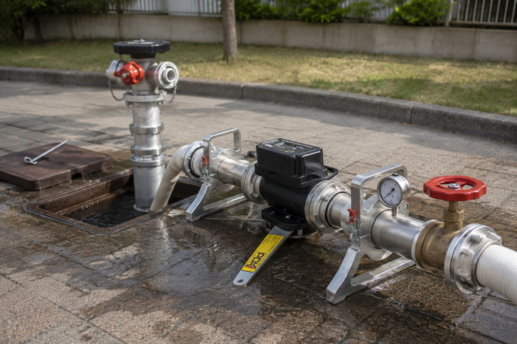
A hydrant may show what appears to be a good pressure of, for example, 5 or 6 bar while closed. However, once a larger quantity of water is drawn, the pressure can drop significantly. This clearly demonstrates why measuring static pressure alone is not sufficient to assess a fire-water withdrawal point.
For a meaningful hydrant test, at least two operating conditions must be distinguished: the pressure without water withdrawal and the pressure during a defined water flow. In addition, it must be known what flow rate is actually available at this residual pressure.
Only the combination of static pressure, flow pressure and flow rate enables a reliable assessment of the hydraulic performance at the measuring point.
It is important to note that a hydrant test initially reflects the behaviour of the network under the actual test conditions created. Whether the measured values are sufficient must then be compared with the requirements, design values or specifications of the operator or water supplier that apply to the specific installation.
Suitable measuring instruments can be found under Hydrant test equipment / hydrant testers. Further solutions for industrial flow measurement are grouped under Flow measurement technology.
Table of Contents
- What is actually checked during a hydrant test?
- What does static pressure mean?
- What does flow pressure mean?
- Why flow rate is decisive
- Evaluating static pressure, flow pressure and flow rate together
- Typical test setup
- Preparing the measurement correctly
- Filling and venting the test section
- Measuring static pressure correctly
- Measuring flow pressure and flow rate
- Considering simultaneous water withdrawal
- Hoses, fittings and pressure losses
- Selecting the correct measuring range for the test device
- Why a single measuring point is not always sufficient
- Performing measurements reproducibly
- Typical errors during hydrant testing
- Recommended test procedure
- Which values should be documented?
- Practical example
- Which products and solutions are suitable?
- Conclusion
- Frequently asked questions
What is actually checked during a hydrant test?
A hydrant test is not only intended to determine whether water comes out of the hydrant.
For hydraulic assessment, the decisive factor is how much water can actually be drawn under defined conditions and what pressure remains available while doing so.
Three values are therefore typically considered:
- Static pressure: Pressure at the hydrant without water being discharged through the test equipment.
- Flow pressure: Pressure at the measuring point during a defined water withdrawal.
- Flow rate: Actual amount of water discharged, for example in l/min or m³/h.
These values should not be considered independently of one another.
For example, a high static pressure can occur together with a significant pressure drop at higher flow rates.
What does static pressure mean?
Static pressure is measured when no water is being discharged through the tested hydrant or test equipment.
It describes the network pressure currently present at that location under the prevailing operating conditions.
Static pressure is an important initial value, but on its own it says little about how capable the water supply is under higher withdrawal conditions.
For example, both a high-performance network and a hydraulically unfavourable pipe network may show 5 bar at static conditions.
Only when water is drawn do pressure losses in pipes, fittings and upstream sections of the network become visible.
The term static pressure should also not be equated with a completely unaffected network condition. During the measurement, consumers elsewhere in the supply network may still be drawing water.
What does flow pressure mean?
Flow pressure is the pressure present at the defined measuring point while water is being withdrawn.
It must therefore always be considered together with the corresponding flow rate.
The statement:
“Flow pressure 3.0 bar”
has only limited significance without the simultaneously discharged quantity of water.
Far more useful would be, for example:
1,500 l/min at 3.0 bar flow pressure.
If the water withdrawal is increased, the flow pressure normally drops further. The extent of this pressure drop depends, among other things, on the pipe network, pipe diameters, pipe lengths, fittings, pumps and the current load on the network.
Why flow rate is decisive
At a fire-water withdrawal point, the key issue is not only the available pressure, but above all the actual amount of water that can be supplied.
The flow rate describes how much water is discharged per unit of time.
Typical units include:
- l/min,
- l/s and
- m³/h.
A reliable statement about performance should therefore always link pressure and flow rate.
A hydrant that still shows a high pressure at a low withdrawal rate may experience a significant pressure drop when more water is drawn.
Conversely, a lower static pressure may still be associated with a good available flow rate if the upstream pipe network is sufficiently dimensioned.
Evaluating static pressure, flow pressure and flow rate together
In simplified terms, a hydrant test can be regarded as a load test.
Without water withdrawal, the initial pressure is first recorded.
The hydrant is then loaded by discharging a defined quantity of water.
As the flow rate increases, the hydraulic pressure loss in the system rises.
A measurement series could, for example, look like this:
| Operating condition | Flow rate | Pressure at measuring point |
|---|---|---|
| No withdrawal | 0 l/min | 5.8 bar |
| Withdrawal 1 | 1,000 l/min | 4.3 bar |
| Withdrawal 2 | 1,500 l/min | 3.4 bar |
| Withdrawal 3 | 2,000 l/min | 2.3 bar |
The figures are only examples. However, they clearly show why the single value “static pressure 5.8 bar” does not describe the available fire-water performance.
Whether, for example, 2,000 l/min at 2.3 bar is sufficient can only be assessed on the basis of the requirements defined for the specific facility or network.
Typical test setup
A defined test section is required for reproducible hydrant testing.
Depending on the test device, it may consist of:
- above-ground or underground hydrant,
- standpipe where required,
- suitable coupling or adapter,
- hydrant test device,
- pressure measurement,
- flow measurement,
- isolation or regulating valve, and
- defined water discharge.
The decisive factor is that the test device used is suitable for the expected pressure, flow rate and hydrant connection.
The discharge of what may be a considerable quantity of water must also be planned before the test begins.
Preparing the measurement correctly
Before the actual measurement, the complete test setup should be prepared.
This includes, among other things:
- clearly identifying the hydrant,
- visually checking the condition of the hydrant,
- checking suitable couplings and seals,
- inspecting the measuring instrument for damage,
- checking the measuring ranges,
- defining the water discharge route,
- considering the hazard area caused by discharged water, and
- obtaining any required operational permits.
A high-performance hydrant can discharge large quantities of water within a short period of time. The discharge direction must therefore not be decided only after the hydrant has been opened.
Loose hoses or insufficiently secured fittings can also be subjected to considerable forces at high flow rates.
Filling and venting the test section
After installation, the test section should be filled with water in a controlled manner.
Valves should not be opened abruptly.
Depending on the setup, air pockets may initially be present in the measuring device, hoses or higher sections.
Trapped air can make stable pressure measurement more difficult and can cause additional dynamic effects when pressure rises quickly.
The test section should therefore be completely filled and, where required, vented in accordance with the operating instructions of the test device.
Only then should the actual measurement series begin.
Measuring static pressure correctly
For static pressure measurement, the hydrant must be hydraulically connected to the measuring device while no water, or only the water withdrawal specified by the test procedure, is discharged through the test outlet.
After pressure has built up, sufficient time should be allowed for the reading to stabilise.
At minimum, the following should be documented:
- static pressure,
- date and time,
- hydrant ID or location, and
- any special network or plant conditions.
The time of measurement is relevant because network loading can vary at different times of day.
Measuring flow pressure and flow rate
After measuring the static pressure, a defined water withdrawal is established.
The valve should be opened in a controlled manner to avoid unnecessary pressure surges.
During water discharge, the following are measured simultaneously:
- flow rate and
- corresponding flow pressure.
The values should only be documented once a sufficiently stable operating condition has been reached.
Depending on the test objective, it may be useful to measure several load points.
This makes it possible to see how strongly the pressure drops as water withdrawal increases.
Such a measurement series provides considerably more information than a single flow value.
Considering simultaneous water withdrawal
For certain supply or fire protection concepts, it is not sufficient to consider only one hydrant in isolation.
The decisive factor may be how much water is available when water is withdrawn simultaneously at several locations.
For example, one hydrant may provide good values when tested alone, while additional withdrawal from a second hydrant causes the flow pressure to fall much more sharply.
Such tests must be planned specifically.
The following should be clearly defined:
- which hydrants are opened simultaneously,
- where the pressure is measured,
- what flow rates occur at the individual withdrawal points, and
- which network condition is to be assessed.
A multi-hydrant test is therefore not simply a repetition of several individual tests, but a defined load test of the supply network.
Hoses, fittings and pressure losses
The test setup itself also causes pressure losses.
Long hoses, small diameters, tight bends, reducers and fittings increase flow resistance.
It must therefore be clearly known where the flow pressure is being measured.
If, for example, the pressure is measured far downstream of a long test hose, the measured value already includes the pressure loss of that hose.
For comparable repeat tests, the same setup or at least a hydraulically comparable setup should be used whenever possible.
Particularly at high flow rates, even small changes in the test setup can have clearly measurable effects.
Selecting the correct measuring range for the test device
A flow meter only operates reliably within its intended measuring range.
A device designed for low flow rates is therefore not automatically suitable for testing a high-capacity large hydrant.
Conversely, a very large measuring instrument may offer poorer usable resolution at low flow rates.
The following should therefore be considered during selection:
- expected maximum flow rate,
- expected pressure,
- connection size,
- hydrant type,
- required measurement accuracy, and
- type of water discharge.
The pressure measuring system must also safely cover the maximum possible network pressure.
Why a single measuring point is not always sufficient
A measurement at one hydrant initially describes the hydraulic conditions at exactly that location and at the time of the test.
It does not automatically provide a complete assessment of the entire supply network.
Possible causes of locally differing results include:
- different pipe diameters,
- long supply lines,
- partially closed valves,
- scaling or deposits,
- elevation differences,
- network structure, and
- simultaneous consumers.
If unusual results are obtained, comparison measurements at additional hydrants may therefore be useful.
This makes it easier to determine whether the cause is local to the hydrant or located in a larger section of the network.
Performing measurements reproducibly
Hydrant tests become particularly valuable when results can be compared over a longer period of time.
For this purpose, the boundary conditions should be kept as constant as possible or at least documented.
These include:
- same hydrant or measuring point,
- same test setup,
- comparable valve positions,
- same or documented load point,
- identical units, and
- known calibration status of the test device.
Only then can it be assessed, for example, whether an increasing pressure loss over several tests actually indicates a change in the network.
Typical errors during hydrant testing
| Observation or error | Possible cause | Recommended check |
|---|---|---|
| Only static pressure is documented | Hydraulic performance under load remains unknown | Additionally measure flow pressure and flow rate |
| High static pressure but low flow pressure | High pressure loss at greater withdrawal | Investigate flow dependency and network conditions |
| Flow rate is recorded without corresponding pressure | Measured value has only limited hydraulic significance | Document flow pressure simultaneously |
| Pressure reading fluctuates strongly after opening | Test section not yet stable or air is trapped | Fill in a controlled manner and allow to stabilise |
| Values differ significantly from the previous year’s test | Different test setup or changed network conditions | Compare test conditions and measuring setup |
| Flow pressure is measured downstream of a long hose | Hose pressure loss affects the measured value | Take the pressure measuring position into account |
| Measuring device reaches the upper end of its flow range | Test device may be undersized | Use a suitable measuring range |
| One hydrant delivers unusually low values | Local problem or network problem possible | Perform comparison measurements at neighbouring points |
Recommended test procedure
- Identify the hydrant: Clearly record location, hydrant ID and connection.
- Define the test objective: Clarify which pressure and flow values or load conditions are to be checked.
- Select the measuring instrument: Choose the pressure range, flow range and connection size appropriately.
- Check the test setup: Inspect couplings, seals, hoses and water discharge.
- Open the hydrant in a controlled manner: Avoid pressure surges.
- Fill the test section: Remove any trapped air where necessary.
- Record static pressure: Document the stable initial pressure.
- Set the water withdrawal: Establish the required load point in a controlled manner.
- Wait for stabilisation: Do not record instantaneous values immediately after opening.
- Measure flow pressure and flow rate simultaneously: Document both values as a corresponding pair.
- Measure additional load points if required: Assess behaviour as water withdrawal increases.
- Close the hydrant slowly: Avoid pressure surges in the network.
- Depressurise the test section: Only then dismantle the equipment.
- Document the measured values: Add test conditions, abnormalities and the test equipment used.
- Compare with requirements: Evaluate the results against the target or minimum values applicable to the specific installation.
Which values should be documented?
A test report should not contain only a single pressure value.
At minimum, it is advisable to record:
- hydrant ID or exact measuring point,
- date and time,
- hydrant type,
- connection or adapter used,
- static pressure,
- flow pressure,
- corresponding flow rate,
- several load points where applicable,
- any additional withdrawal points opened simultaneously,
- test equipment used,
- special observations, and
- evaluation against the intended target value.
The condition of the hydrant can also be documented, for example stiff operation, leaks or unusual noises and vibrations.
With regular repeat testing, this makes it possible to identify developments over several years.
Practical example
An industrial facility wants to check the performance of an outdoor hydrant.
With the hydrant closed, a static pressure of 6.1 bar is measured.
At first, this value appears comfortable.
A water withdrawal of 1,000 l/min is then set. The flow pressure is still 4.7 bar.
At 1,500 l/min, the pressure falls to 3.6 bar.
When the flow is increased further to 2,000 l/min, the flow pressure drops to 2.1 bar.
This significant pressure drop would not have been apparent from the static pressure of 6.1 bar alone.
An additional measurement at a neighbouring hydrant shows significantly better performance.
This suggests that the entire water supply is not necessarily inadequate, but that there may be additional hydraulic resistance in the supply path to the first hydrant.
The subsequent investigation therefore focuses on the relevant pipe section and the fittings installed there.
The example shows why static pressure, flow pressure and flow rate should be measured together and why comparison measurements at several points can be helpful during troubleshooting.
Which products and solutions are suitable?
Mobile hydrant test device – directly measure static pressure, flow pressure and flow rate
The mobile hydrant test device is suitable for performance testing of above-ground and underground hydrants.
With one device, the key parameters required for hydraulic assessment can be measured directly at the withdrawal point:
- static pressure,
- flow pressure and
- flow rate.
The test device is available in different connection sizes and flow ranges. This allows the configuration to be adapted to the expected flow rate and the respective hydrant connection.
Direct flow measurement is particularly practical because both pressure and the actual discharged water quantity can be measured under the same load condition.
Adapters, standpipes and measuring sections
Suitable standpipes, couplings and adapters are required for underground hydrants and different connection sizes.
Unnecessary chains of reducers and restrictions should be avoided because additional flow resistance can influence the test setup.
The inlet and outlet conditions of the flow meter used should also be designed in accordance with the device requirements.
Pressure measurement and network monitoring
If not only a short hydrant test but also the pressure behaviour of a water network over a longer period is to be investigated, additional pressure sensors or data loggers may be useful.
This makes it possible, for example, to observe how network pressure changes during different consumption periods or during defined withdrawal tests.
Further solutions for measuring water flow can be found under Flow measurement technology.
ICS Schneider Messtechnik supports you in selecting hydrant test equipment, suitable measuring ranges, couplings, adapters and accessories, as well as in configuring complete test equipment for hydrants and fire-water systems.
Conclusion
A high static pressure alone is not sufficient evidence of a high-performance fire-water supply.
The decisive factor is how the pressure behaves when water is actually being drawn.
For this reason, three values always belong together in a meaningful hydrant test:
Static pressure, flow pressure and flow rate.
The static pressure describes the initial condition. The flow pressure shows how much pressure remains during water withdrawal. The flow rate describes the actual quantity of water being discharged.
A measurement series with several load points is particularly informative. It shows how strongly the pressure drops as water withdrawal increases.
The test setup also influences the result. Hoses, adapters, fittings and the location of the pressure measurement must therefore be taken into account and kept as constant as possible for repeat tests.
A measurement at only one hydrant also does not automatically provide information about the entire network. If unusual results occur, additional measuring points or defined simultaneous withdrawals may be required.
Only by comparing reproducibly measured values with the requirements applicable to the specific installation can the available fire-water supply be assessed correctly.
Frequently asked questions about hydrant testing
What is the static pressure of a hydrant?
Static pressure is the pressure present at the measuring point when no water is being withdrawn through the test equipment. It describes the initial condition, but on its own does not indicate how much water is available under higher withdrawal conditions.
What is flow pressure?
Flow pressure is the pressure at the measuring point during a defined water withdrawal. It should always be documented together with the simultaneously measured flow rate.
Why is a pressure measurement alone not sufficient?
Because high pressure at low or zero withdrawal does not automatically mean that a large quantity of water is also available. Hydraulic pressure losses in the supply system only become visible under load.
How is the flow rate of a hydrant measured?
The flow rate can, for example, be measured using a suitable mobile hydrant test device or a defined flow measurement section. The measuring instrument must be suitable for the expected flow range and connection.
Do static pressure and flow pressure have to be measured at the same hydrant?
For a direct comparison, the measurement conditions should be clearly defined. In extended network tests, additional pressures or flow rates may also be measured at other hydrants.
Why does the pressure drop when the hydrant is opened?
As water flow increases, pressure losses occur in pipes, fittings and other components of the supply network. The flow pressure is therefore normally lower than the static pressure.
Is a high static pressure automatically good?
No. The decisive factor is how much pressure remains at the required water withdrawal rate. A high static pressure can still be accompanied by a strong pressure drop under load.
Why should several flow stages be measured?
Several load points show how the system reacts to increasing water withdrawal. This makes it possible to assess hydraulic performance much more effectively than with a single measured value.
Does the test hose influence the measurement result?
Yes. Hose length, diameter, bends and fittings cause flow losses. The test setup and the position of the pressure measurement should therefore be known and kept as constant as possible for comparison measurements.
Which values are considered sufficient in a hydrant test?
There is no single value that should be used independently of the installation and application. The measured values must be compared with the requirements, design values and specifications applicable to the specific facility or supply network.