


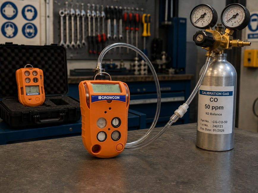
A portable gas detector is exposed to test gas before use. The sensor responds, the measured value increases, and the audible, visual and vibrating alarms are activated. The bump test is therefore considered passed.
However, the subsequent calibration check produces a different result: for example, the test gas cylinder contains a known concentration of 50 ppm, but the instrument stabilizes at only around 35 ppm. Or the measured value reaches the expected concentration significantly later than specified.
How can a gas detector pass the bump test and still show problems during calibration?
The apparent contradiction arises because the two tests answer different questions.
The bump test primarily checks: Does the gas detector respond to gas and does the alarm function correctly?
A calibration or accuracy check, on the other hand, answers:
How accurately does the displayed measured value correspond to a known test gas concentration?
A sensor may therefore still be sensitive enough to trigger an alarm even though its sensitivity has already decreased significantly.
In addition, a distinction must be made between sensor deviation and delayed gas delivery. Particularly with instruments using a pump, test gas hose or long sampling lines, hose volume, flow rate, filters and dead volume can influence the time it takes for the test gas to actually reach the sensor.
Portable instruments for personal protection and pre-entry measurements can be found at ICS Schneider under Portable Gas Detectors. An overview of further solutions can be found under Gas Measuring Instruments / Gas Detectors.
Table of Contents
- Distinguishing between bump test, calibration check and adjustment
- Why a bump test can pass despite a measurement deviation
- Example: alarm works, but the measured value is still too low
- Selecting and applying the test gas concentration correctly
- Correctly evaluating zero point and zero gas
- What does the T90 response time mean?
- Distinguishing between gas transport time and sensor response time
- Influence of test gas hose and hose volume
- Regulator flow rate and gas supply
- Distinguishing between pumped and diffusion instruments
- Checking filters, adapters and sensor openings
- Recognizing sensor drift and loss of sensitivity
- Correctly evaluating measurement deviation
- What to do if the calibration limit is exceeded?
- When the sensor or gas detector should be replaced
- Typical fault patterns
- Systematic troubleshooting
- Practical example: CO sensor passes bump test but reads too low
- Suitable ICS products
- Conclusion
- FAQ
Distinguishing between bump test, calibration check and adjustment
In practice, the terms bump test, calibration and adjustment are often mixed up.
From a metrological perspective, however, they serve different purposes.
Bump test or functional test
During a bump test, the gas detector is briefly exposed to suitable test gas.
The following points are checked in particular:
- does gas reach the sensor,
- does the sensor respond at all,
- does the display increase or decrease in the expected direction,
- is the alarm threshold reached,
- does the audible alarm work,
- does the visual alarm work,
- does the vibration alarm work, where applicable.
A conventional bump test is therefore primarily a functional check.
It is not automatically a complete quantitative accuracy check across the measuring range.
With automated test stations, additional manufacturer-specific criteria for response time and signal level may also be evaluated. The test procedure defined for the specific instrument is therefore always decisive.
Calibration check
During a calibration or accuracy check, the displayed measured value is compared with a known test gas concentration.
For example:
Test gas: 50 ppm CO
Instrument reading: 48 ppm CO
The measurement deviation can be determined from the difference.
Whether this deviation is permissible depends on:
- manufacturer specifications,
- sensor type,
- measuring range,
- company test procedure,
- applicable standards or regulations, where relevant.
There is no universally applicable tolerance for all gas detectors and sensors.
Adjustment
If the instrument shows an impermissible deviation, an adjustment can be carried out depending on the instrument.
The instrument characteristic or sensor sensitivity is adjusted so that the reading once again matches the known test gas concentration.
A technically correct distinction should therefore be made between:
- Calibration: determine the deviation,
- Adjustment: set or correct the measuring instrument,
- recheck: verify that the required accuracy is subsequently achieved.
Why a bump test can pass despite a measurement deviation
The most important relationship can be explained using the alarm threshold.
Assume that, due to ageing, a sensor now responds with only around 70% of its original sensitivity.
A sufficiently high test gas concentration can still generate a measured value above the configured alarm threshold.
The instrument:
- detects gas,
- shows an increasing measured value,
- exceeds the alarm threshold,
- activates all alarms.
The bump test may therefore appear successful.
During a quantitative test, however, it becomes clear:
The sensor still responds, but no longer with the correct sensitivity.
This is precisely why:
Bump test passed
must not automatically be interpreted as:
Measurement accuracy fully acceptable
Example: alarm works, but the measured value is still too low
A simplified example illustrates the difference.
Assume:
- alarm threshold of a CO channel: 25 ppm,
- test gas used: 50 ppm CO.
Under defined test conditions, a correctly functioning sensor should provide a measured value close to the known test gas concentration.
However, an aged sensor displays only:
32 ppm CO
The instrument still exceeds the alarm threshold of 25 ppm.
The alarm sounds.
A simple bump test may therefore have achieved its functional objective.
However, the measurement deviation from the test gas is:
50 ppm - 32 ppm = 18 ppm
or, relative to the test gas concentration:
18 / 50 × 100% = 36%
Such a large deviation would obviously be critical for many measurement tasks.
The values shown are only a calculation example and are not universally applicable alarm or tolerance values.
Selecting and applying the test gas concentration correctly
The quality of a calibration check depends directly on the test gas supply used.
The following should be checked in particular:
- correct gas type,
- correct concentration,
- correct carrier gas composition,
- validity or expiry date of the test gas cylinder,
- suitable pressure reducer or flow regulator,
- suitable test gas hose,
- correct calibration adapter,
- sufficient exposure time.
Especially with multi-gas instruments, it must be ensured that the test gas mixture used actually matches the installed sensor configuration.
An incorrect test gas concentration can appear to be a sensor fault.
Check the configured calibration value
With some instruments or test stations, the nominal concentration of the gas cylinder being used must be entered.
If the cylinder is labelled, for example:
50 ppm CO
while the instrument has accidentally been configured for:
100 ppm CO
a technically correct sensor response may be interpreted as a significant under-reading.
Before deciding that the sensor is faulty, always check:
Does the configured calibration value match the certificate or label of the test gas cylinder actually connected?
Correctly evaluating zero point and zero gas
Before checking sensitivity, the sensor zero point must be correct.
In many applications, zeroing can be performed in clean ambient air.
However, this assumes that the environment is actually free of relevant target gases and interfering concentrations.
If this cannot be reliably ensured, suitable zero gas may be required.
An incorrect zero point shifts the entire measurement.
Example:
correct zero point: 0 ppm
actual offset: +8 ppm
During subsequent exposure to test gas, this can distort the assessment of sensor sensitivity.
Never force a zero adjustment in an unknown atmosphere
For example, it would be problematic to zero a CO sensor in an area where a low CO concentration is actually already present.
The instrument would interpret this existing concentration as zero.
During later measurements, the instrument could therefore systematically under-read.
Therefore:
Only zero under conditions that are actually suitable as a zero reference according to the manufacturer’s instructions.
What does the T90 response time mean?
In addition to measurement deviation, the time response is also important for gas detectors.
A frequently used parameter is the response time:
T90
In simplified terms, T90 describes the time a measuring system requires after a step change in gas concentration to reach 90% of its stabilized final value.
Assume a sensor changes from:
0 ppm
to sudden exposure to:
100 ppm
.
If the stabilized final reading is 100 ppm, the relevant point for the T90 assessment is:
90 ppm
.
If this value is reached after, for example, 25 seconds, the T90 determined under these defined conditions is approximately:
T90 = 25 s
However, a T90 specification can only be meaningfully compared when the test conditions are known.
Sensor T90 is not automatically the response time of the complete measurement system
In a real application, the measurement chain consists of more than just the sensor element.
For example:
Gas source → hose → filter → pump → measurement chamber → sensor → signal processing → display
Each element can cause additional delay.
A sensor with a fast intrinsic response can therefore still show a significantly delayed change when used with a long sampling line.
Distinguishing between gas transport time and sensor response time
If the gas response is unusually slow, the first question should be:
Does the test gas reach the sensor too late, or is the sensor itself responding too slowly?
These are two different fault patterns.
Transport delay
A transport delay can be caused, for example, by:
- long test gas hose,
- large hose internal diameter,
- low flow rate,
- large adapter volumes,
- long sampling lines,
- filter volume.
Sensor delay
The sensor response itself can be influenced, among other things, by:
- sensor principle,
- sensor ageing,
- temperature,
- humidity,
- filter condition,
- contamination,
- poisoning or damage to certain sensor types.
This distinction is crucial for troubleshooting.
Influence of test gas hose and hose volume
With pumped gas detectors and external test gas setups, the hose has its own internal volume.
This volume must first be filled with test gas.
For a straight hose, the geometric internal volume can be approximated by:
V = π · d² / 4 · L
where:
- V = internal hose volume,
- d = internal diameter,
- L = hose length.
Example
Assume:
- hose length: 3 m,
- internal diameter: 4 mm.
The geometric internal volume is approximately:
V ≈ 37.7 ml
At an assumed volume flow of:
500 ml/min
the purely geometric time required for one simple volume exchange is approximately:
t ≈ 37.7 / 500 min
t ≈ 4.5 s
This example is only a theoretical illustration.
The actual transport and response time may be longer because the following can also play a role:
- mixing,
- sensor response,
- filters,
- adapter volume,
- adsorption on surfaces.
Do not confuse a long sampling line with a sensor fault
If the time measurement is started as soon as the test gas cylinder is opened, even though several meters of hose are located between the cylinder and sensor, the result contains:
transport time + instrument time + sensor response time
The time determined in this way cannot simply be compared with a pure sensor T90 value from a data sheet.
Regulator flow rate and gas supply
The test gas flow rate must match the measuring instrument and test procedure being used.
A flow rate that is too low can, for example, result in:
- insufficient test gas being available,
- ambient air being mixed in,
- the concentration at the sensor being lower than expected,
- the response time appearing longer.
An unnecessarily high flow rate is not automatically better either.
The test cap, sensor and gas path are designed for defined operating conditions.
An arbitrary regulator should therefore not be used.
Flow regulator, test cap and connection method must comply with the gas detector manufacturer’s specifications.
Fixed-flow or demand-flow regulator
Different gas regulators can be used depending on the instrument and test concept.
A fixed-flow regulator provides a defined volume flow.
A demand-flow regulator supplies gas according to the requirements of the connected system.
The correct variant depends in particular on:
- pumped operation,
- diffusion operation,
- calibration adapter,
- manufacturer approval.
Distinguishing between pumped and diffusion instruments
With portable gas detectors, there are two fundamentally different ways in which gas reaches the sensor.
Diffusion operation
With a diffusion instrument, ambient gas reaches the sensor opening without an active sampling pump.
For personal protection, this is often a very compact and robust solution.
During the bump test, test gas is directed to the sensors via a dedicated test cap or calibration plate.
Pumped operation
With a pumped instrument, the sample is actively drawn in.
This is used, for example, for pre-entry measurements when the atmosphere must be checked from a distance or from inside a vessel or confined space.
With this type of measurement, the measurement chain additionally includes:
- pump,
- sampling hose,
- probe where applicable,
- filter,
- connection adapter.
This increases the number of possible causes of delayed response or low readings.
Same instrument, different response time
A gas detector may therefore respond quickly when test gas is applied directly, but significantly later when measurements are taken through a long sampling line.
This does not automatically mean that the sensor itself has changed.
The additional transport path must be taken into account.
Checking filters, adapters and sensor openings
Before classifying a sensor as faulty, the entire gas path should be checked.
Typical inspection points include:
- sensor opening,
- dust filter,
- hydrophobic filter,
- test gas cap,
- calibration adapter,
- hose,
- hose couplings,
- pump inlet.
A partially blocked filter may still allow gas to reach the sensor.
The sensor may therefore still respond sufficiently to trigger an alarm, but:
- more slowly,
- with a lower transient measured value,
- only after longer exposure to test gas.
This behavior can initially look like sensor drift.
Recognizing sensor drift and loss of sensitivity
Gas sensors are not completely stable components over time.
Sensor sensitivity can change during use.
Possible influencing factors include:
- ageing,
- high or low temperatures,
- humidity,
- frequent gas exposure,
- over-range exposure,
- contamination,
- certain interfering substances,
- mechanical or electrical ageing.
Typical indications of a loss of sensitivity include:
- test gas concentration is consistently under-read,
- increasingly large adjustment is required,
- response time increases,
- measured value does not stabilize,
- calibration must be repeated unusually frequently.
Drift does not always mean under-reading
Sensor deviations can generally occur in either direction.
An instrument may:
- read too low,
- read too high,
- have a shifted zero point,
- have altered sensitivity.
It is therefore not sufficient merely to check whether an alarm occurs at all.
Correctly evaluating measurement deviation
For a simple assessment, the absolute measurement deviation can be calculated as:
ΔC = Cdisplay - Ctest gas
The relative deviation referred to the test gas concentration is:
δ = (Cdisplay - Ctest gas) / Ctest gas · 100%
Example:
Test gas = 100 ppm
Reading = 88 ppm
This gives:
ΔC = -12 ppm
and:
δ = -12%
Whether this deviation is acceptable must not be decided solely on the basis of an arbitrarily selected percentage limit.
The acceptance criteria defined for the specific instrument and test procedure are decisive.
What to do if the calibration limit is exceeded?
If an impermissible deviation is identified during an accuracy check, the sensor should not be replaced immediately.
The following should first be checked systematically:
- Is the correct test gas cylinder connected?
- Is the test gas concentration correct?
- Is the test gas still within its permitted period of use?
- Is the correct nominal concentration configured in the instrument?
- Is the zero point correct?
- Is the correct calibration adapter installed?
- Is the hose suitable and leak-tight?
- Is the gas flow rate correct?
- Are the filters and sensor openings clear?
- Was test gas applied for long enough?
- Is the ambient temperature within the permissible range?
- Has the correct target gas or calibration gas been selected?
Only after these points have been ruled out should the sensor sensitivity itself be assessed more closely.
Perform adjustment
If the instrument is fundamentally functional, an adjustment can be performed in accordance with the manufacturer’s instructions.
It should then be checked again using known test gas.
A successful adjustment does not merely mean:
Instrument completed the adjustment function
but rather:
The subsequent measured value must once again lie within the acceptance limits specified for the instrument.
When the sensor or gas detector should be replaced
Sensor replacement or repair becomes particularly relevant if, despite a correct test setup, the instrument:
- can no longer be adjusted successfully,
- repeatedly lies outside the permissible measurement deviation,
- has an impermissibly long response time,
- does not reach a stable measured value,
- shows a strongly drifting zero point,
- reports a sensor fault,
- no longer reliably passes the bump test.
The specific replacement decision must be made in accordance with the manufacturer’s requirements for the sensor and instrument.
For safety-related gas detectors, an instrument with an unresolved test or calibration fault should not simply continue to be used.
Typical fault patterns during bump testing and calibration
| Observation | Possible cause | Recommended check |
|---|---|---|
| Bump test passed, calibration value significantly too low | Sensor still responds sufficiently for an alarm but has reduced sensitivity | Check test gas supply and repeat the quantitative calibration check |
| Alarm is triggered quickly, but final value remains too low | Sensor sensitivity or incorrect calibration value | Check test gas concentration and sensor calibration |
| Measured value increases very slowly but eventually reaches the correct value | Transport delay, filter or extended sensor response | Investigate hose, flow rate and response time separately |
| Fast with a short hose, significantly slower with a long hose | Gas transport time | Take hose volume and pump flow rate into account |
| Reading too low and unstable | Test gas flow rate too low or leakage | Check regulator, connections and calibration adapter |
| All sensors of a multi-gas instrument simultaneously read too low | Possible problem with the common test gas supply | Check gas cylinder, pressure reducer, hose and flow rate |
| Only one sensor reads significantly too low | Sensor-specific or gas-specific problem more likely | Check individual channel, sensor age and calibration data |
| Measured value does not start at zero | Zero-point error or contaminated zero atmosphere | Recheck using a suitable zero reference |
| Calibration suddenly works again with a new test gas cylinder | Old, incorrect or unsuitable test gas | Document cylinder data and validity |
| Bump test increasingly takes longer | Filter contamination, sensor ageing or gas transport problem | Check response-time trend and gas path |
| Pumped instrument responds normally without hose but poorly with sampling hose | Hose, filter, leakage or transport delay | Check the sampling path section by section |
| Instrument can no longer be adjusted successfully | Sensor at the end of its usable range or technical fault | Perform manufacturer diagnostics or sensor service |
Systematic troubleshooting after a passed bump test and failed calibration
A structured procedure prevents functioning sensors from being replaced unnecessarily and genuine sensor problems from being overlooked.
- Define the test result precisely: What does “bump passed” mean for the instrument or test station being used?
- Identify the test gas: Document gas type, concentration, carrier gas and cylinder number.
- Check validity: Verify the expiry date or certificate of the test gas.
- Check the nominal value: Compare the configured calibration gas concentration with the cylinder.
- Check the zero point: Zero the instrument only in a suitable zero atmosphere.
- Check the gas path: Inspect adapter, filter, hose and sensor opening.
- Check the flow rate: Use a regulator suitable according to the manufacturer.
- Document hose length: Particularly for pumped instruments and remote sampling.
- Take transport time into account: Do not automatically interpret the time as sensor T90.
- Apply test gas for a sufficient period: Observe stabilization time or manufacturer procedure.
- Document the final value: Do not record only “alarm yes/no”.
- Document response time: Clearly define the point at which gas exposure begins.
- Compare sensors individually: With multi-gas instruments, check whether only one channel is affected.
- Perform adjustment: Only in accordance with the manufacturer’s instructions.
- Perform a verification measurement: After adjustment, recheck using known test gas.
- Review the trend: Compare previous bump-test and calibration data.
- Decide on replacement: Replace the sensor or repair the instrument if the required criteria can no longer be achieved.
- Document the test: Record test gas, instrument, sensor, date, results and actions taken.
Practical example: CO sensor passes bump test but reads too low
A portable multi-gas detector is regularly tested before use.
During the most recent functional test, the CO channel shows no obvious fault.
Step 1: bump test
After exposure to test gas, the CO reading rises quickly.
The alarm is triggered.
Audible, visual and vibration alarms function correctly.
The functional test is initially considered passed.
Step 2: quantitative check
The instrument is then exposed to a known CO test gas concentration.
The cylinder contains, for example:
50 ppm CO
After sufficient exposure, however, the reading stabilizes at only:
36 ppm CO
The sensor therefore clearly responds to CO, but its sensitivity appears too low.
Step 3: check the test gas supply
Before evaluating the sensor, the following are checked:
- gas type,
- cylinder concentration,
- validity,
- regulator,
- hose,
- calibration adapter.
No abnormality is identified.
Step 4: check the zero point
The zero point is checked again under suitable conditions.
No relevant deviation is found here either.
Step 5: adjustment
The instrument is adjusted using the known test gas concentration in accordance with the manufacturer’s instructions.
The test is then repeated.
Step 6: verification measurement
If the measured value subsequently lies within the manufacturer’s permissible limits again, the sensor can generally continue to be used provided that all other test criteria are also met.
If the sensitivity can no longer be corrected sufficiently, repair or sensor replacement will be required.
Result
The originally passed bump test was not incorrect.
It had correctly demonstrated:
The sensor responds to gas and the instrument generates an alarm.
However, it had not demonstrated:
The sensor still measures the gas concentration with sufficient accuracy.
Suitable ICS products for bump testing, calibration and portable gas monitoring
Crowcon T4 – portable 4-gas personal protection instrument
The Crowcon T4 offered by ICS is a portable multi-gas detector for personal protection.
Depending on the configuration or standard version, typical gas hazards such as:
- carbon monoxide CO,
- hydrogen sulfide H₂S,
- flammable gases,
- oxygen O₂
are monitored.
The instrument provides audible, visual and vibration alarms and is designed for regular bump and calibration checks.
A corresponding test station is available for automated testing.
Further information can be found under Crowcon T4 at ICS Schneider.
Crowcon Gas-Pro – multi-gas detector with optional pump
The Crowcon Gas-Pro is particularly suitable when pre-entry measurements are required in addition to personal gas detection.
The instrument can monitor up to five gases and is available with an internal pump depending on the version.
The Gas-Pro can therefore be used both:
- in diffusion mode,
- and for pumped sampling.
Especially in pumped operation, the influences of sampling hose, transport time, filters and gas path described in this article are particularly relevant.
The Gas-Pro also features reminder functions for bump testing and calibration.
Further information can be found under Crowcon Gas-Pro at ICS Schneider.
Crowcon I-Test – automated bump and calibration testing
The Crowcon I-Test offered by ICS can be used to automate testing of compatible Gas-Pro and T4 instruments.
The system:
- automatically starts the test after the instrument is inserted,
- performs bump tests,
- checks sensor response,
- checks alarm functions,
- supports calibration procedures,
- stores bump-test and calibration data,
- enables documented test reports.
An automated test station offers one major advantage:
Test gas supply, test sequence, evaluation and documentation are more reproducible than with changing manual test setups.
Further information can be found under Crowcon I-Test at ICS Schneider.
Which solution is suitable for which task?
| Task | Recommended solution |
|---|---|
| Personal 4-gas protection | Crowcon T4 |
| Multi-gas monitoring with optional sampling pump | Crowcon Gas-Pro |
| Pre-entry measurement from a vessel or confined space | Gas-Pro with suitable pump and sampling configuration |
| Regular manual functional testing | Gas detector with suitable test gas and approved test adapter |
| Automated bump testing of T4 or Gas-Pro | Crowcon I-Test |
| Documentation of numerous instrument tests | Automated test station with test and calibration data storage |
Further instruments can be found under Portable Gas Detectors at ICS Schneider.
Conclusion
A passed bump test and a failed calibration check are not contradictory.
The two tests assess different characteristics of the gas detector.
The bump test essentially answers:
Does test gas reach the sensor, does the instrument respond and does the alarm function correctly?
The quantitative calibration check, on the other hand, answers:
How accurately does the displayed value correspond to a known gas concentration?
A sensor with reduced sensitivity can therefore still trigger an alarm while significantly under-reading the actual concentration.
However, an abnormal test result should not automatically be attributed to sensor drift.
The complete measurement chain also includes:
- test gas cylinder,
- test gas concentration,
- zero point,
- regulator,
- hose,
- filter,
- calibration adapter,
- pump,
- sensor.
Particularly with pumped instruments, a distinction must also be made between gas transport time and the actual sensor response time.
A long sampling line can significantly delay the visible response without the actual T90 of the sensor element having deteriorated to the same extent.
Conversely, a sensor may take increasingly longer to reach the correct final value even when gas is applied directly. In this case, the sensor response itself must be investigated more closely.
For practical applications, the procedure is therefore:
Check bump result → verify known test gas concentration → ensure correct zero point → check gas path and flow rate → account for transport time → document final value and response time → compare measurement deviation with manufacturer specification → adjust if necessary → perform verification test → if behavior remains unacceptable, repair or replace sensor or instrument.
FAQ: Bump testing and calibration of gas detectors
What is the difference between a bump test and calibration?
A bump test primarily checks basic sensor response and alarm function. During a calibration check, the displayed measured value is compared with a known test gas concentration.
Can a gas detector pass the bump test and still measure incorrectly?
Yes. A sensor can still respond sufficiently to exceed an alarm threshold even though its sensitivity has already decreased and the displayed value deviates significantly from the actual concentration.
Does a passed bump test prove measurement accuracy?
A simple functional test does not automatically prove quantitative measurement accuracy. Depending on the automated test procedure, however, additional manufacturer-specific response criteria may also be checked.
What is checked during a bump test?
Typically, the test verifies whether test gas reaches the sensor, the sensor responds, the alarm threshold is reached, and the audible, visual and, where applicable, vibration alarms function correctly.
What is checked during a calibration check?
The instrument reading is compared with a known test gas concentration. The measurement deviation can then be determined.
What is the difference between calibration and adjustment?
Calibration determines the measurement deviation. Adjustment corrects the measuring instrument or its sensor characteristic in order to reduce the deviation.
Why does my gas detector read too low when exposed to test gas?
Possible causes include sensor drift, an incorrect zero point, unsuitable or incorrect test gas, an incorrect nominal concentration, insufficient flow, leaks, contaminated filters or insufficient exposure time.
What does T90 mean for a gas detector?
In simplified terms, T90 describes the time required to reach 90% of the stabilized final signal after a change in concentration.
Is T90 the same as the time until the alarm is triggered?
No. The alarm can be triggered before 90% of the final value is reached. The alarm time also depends on the configured alarm threshold.
Is T90 the same as the response time of a long sampling line?
No. With a long line, additional gas transport time must be included. The observed total time can therefore be significantly longer than the pure sensor response time.
Why does a pumped gas detector respond more slowly with a long hose?
The test gas must first flow through the internal volume of the hose. Depending on hose length, internal diameter and pump flow rate, this creates additional transport time.
Can I calculate the transport time of a hose?
As a rough geometric estimate, the hose volume can first be calculated using V = π × d² / 4 × L and then divided by the volume flow. The actual response time may be longer due to mixing, adsorption, filters and sensor response.
Does the test gas flow rate influence calibration?
Yes. An unsuitable flow rate can influence both the concentration at the sensor and the observed response time. The regulator specified for the respective instrument must therefore be used.
Can I use any flow regulator with a gas detector?
No. Regulator, test cap and test procedure must match the instrument version and the manufacturer’s requirements.
Why is the zero point important before calibration?
A shifted zero point distorts the subsequent assessment of sensor sensitivity. The zero adjustment must therefore be carried out under suitable conditions.
Can I simply zero a gas detector in normal ambient air?
Only if it is ensured that the air may be used as a suitable zero reference for the sensor concerned and that no relevant target gas concentration is present. Otherwise, suitable zero gas may be required.
Can a contaminated filter affect a bump test?
Yes. A partially blocked filter can slow down the gas supply. The instrument may still alarm while the response becomes significantly slower.
What does sensor drift mean?
Sensor drift refers to a change in the sensor signal or characteristic over time. This can alter the zero point or sensitivity, for example.
Can sensor drift cause both under-reading and over-reading?
Yes. Depending on the sensor and cause of the fault, both positive and negative measurement deviations can occur.
When should a sensor be adjusted?
If a calibration check shows a deviation outside the manufacturer’s permissible limits and the instrument is designed for adjustment, it should be adjusted in accordance with the manufacturer’s instructions.
What must be done after an adjustment?
The measurement should be checked again using known test gas to confirm that the required accuracy has been restored.
When must a gas sensor be replaced?
Replacement may be required if the sensor can no longer be adjusted successfully, repeatedly lies outside the permissible criteria, does not reach a stable measured value or has an impermissible response time.
Why should I retain old calibration data?
By comparing several tests, it is possible to determine whether the sensitivity or response time of a sensor is gradually deteriorating. Such a trend can be very useful for preventive maintenance.
Why should I document more than just “passed” during a bump test?
If the system used provides the corresponding data, response time, sensor values and previous tests can also be useful for condition assessment.
What is the difference between pumped and diffusion operation?
In diffusion mode, gas reaches the sensor without an active sampling pump. In pumped mode, the sample is actively drawn through a pump, hose and, where applicable, a probe.
What additional sources of error exist with pumped instruments?
In addition to the sensor, the pump, sampling hose, filters, leaks, hose volume and gas transport time can influence the measurement result.
Which ICS gas detector is suitable for standard 4-gas personal protection?
The Crowcon T4 monitors typical hazards from carbon monoxide, hydrogen sulfide, flammable gases and oxygen and is designed as a portable personal protection instrument.
Which instrument is additionally suitable for pumped pre-entry measurements?
Depending on the version, the Crowcon Gas-Pro is available with an internal pump and can therefore also be used for sampling or pre-entry measurements.
Can bump tests be automated?
Yes. For compatible Crowcon T4 and Gas-Pro instruments, ICS offers, for example, the I-Test station for automated bump and calibration procedures as well as the associated documentation.
Where can I find portable gas detectors at ICS Schneider?
An overview can be found under Portable Gas Detectors at ICS Schneider.
Where can I find further gas measuring instruments and gas detectors?
An overview can be found under Gas Measuring Instruments / Gas Detectors at ICS Schneider.