


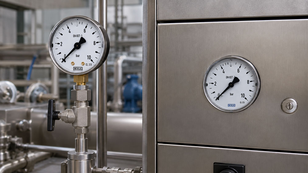
A pressure gauge with a measuring range of 0 … 10 bar can be perfectly suited to the application from a metrological perspective and still turn out to be the wrong version. A typical example: the existing pressure connection is located directly below the planned panel cutout, but a pressure gauge with a rear connection was ordered. Or the instrument has the correct connection but cannot be aligned after installation so that the dial can be read by the operator.
When selecting a mechanical pressure gauge, two different characteristics must therefore be considered separately: the connection position on the case and the actual design of the process connection. Terms such as radial, axial, rear connection, G 1/2 B or 1/2 NPT do not describe the same thing.
Particularly in control panels, hydraulic power units, pipelines and compact machines, the connection position determines how much installation depth is required, how the pressure line can be routed and whether mechanical forces act on the measuring instrument. In addition, measuring range, medium, pressure load, vibration and the intended operating position must be taken into account.
Radial or axial is therefore not a question of measurement accuracy, but primarily a mechanical selection criterion. The correct connection position simplifies installation, readability and pipe routing and prevents the pressure gauge from being mechanically stressed by unsuitable piping or forced alignment.
Suitable instruments can be found at ICS Schneider under Pressure Measurement Technology as well as under Pressure Gauges and Digital Pressure Gauges.
A simple example of the different connection positions is provided by the WIKA models 111.10 and 111.12. Model 111.10 is designed with a lower radial connection, while model 111.12 has a rear connection. For dedicated panel mounting, the WIKA models 111.16 and 111.26 with rear process connection are also available.
Table of Contents
- What does the connection position of a pressure gauge mean?
- What does a radial connection mean?
- What does an axial or rear connection mean?
- Distinguishing between center back and lower back connections
- Direct comparison of radial and rear connections
- Do not confuse connection position with process thread
- Correctly seal G threads and NPT threads
- When a radial connection is suitable for direct mounting
- Why rear connections are useful for panel mounting
- Consider the installation depth behind the panel
- Plan the viewing angle and dial position
- Do not forcibly align the pressure gauge via the threaded connection
- Mechanically relieve the piping and pressure gauge
- Distinguish between connection position and operating position
- Consider vibration and pulsation
- Do not try to solve overload and pressure spikes through the connection position
- Consider hot media and pressure lines
- Consider contact pressure gauges and electrical connections
- Replace an existing pressure gauge with a different connection position
- Typical errors with radial and rear-connected pressure gauges
- Practical example: pressure gauge directly on a hydraulic line
- Practical example: pressure gauge in a control panel
- Systematically select the connection position
- Suitable pressure gauges at ICS Schneider
- Conclusion
- FAQ
What does the connection position of a pressure gauge mean?
The connection position describes where and in which direction the pressure connection exits the pressure gauge case.
Typical designations are:
- lower radial,
- center back,
- lower back or eccentric rear.
In everyday use, the terms:
radial
and:
axial
are also frequently used.
The manufacturer’s terminology is important
The terms are not always used completely consistently throughout the market. For ordering purposes, it is therefore preferable not to specify only “axial”, but to state as clearly as possible:
center back
or:
eccentric rear / lower back
.
Likewise:
lower radial
is more precise than simply:
radial
.
What does a radial connection mean?
With a radial connection, the process connection exits radially from the circumference of the pressure gauge case.
The most common version in industrial applications is:
lower radial connection
or the:
6 o'clock position
.
The process thread points downward while the dial is oriented vertically toward the operator.
Typical applications
- direct mounting on valves,
- mounting on pressure gauge cocks,
- hydraulic power units,
- compressors,
- pipelines,
- test benches,
- general machinery.
Advantage of the lower connection position
A pressure line approaching from below can be routed directly into the instrument.
The arrangement:
pressure line → shut-off valve → pressure gauge
can often be implemented very compactly.
The case remains above the measuring point and is easy to see.
What does an axial or rear connection mean?
With an axial connection, the process connection is located at the rear of the pressure gauge and points approximately in the direction of the pointer axis.
For this reason, the terms:
axial connection
and:
rear connection
are often used interchangeably.
Technically, however, the term “rear connection” is more precise because the connection may additionally be arranged:
- centrally,
- eccentrically.
Typical application
A rear connection is particularly practical when the pressure gauge should be visible from the front while the pressure line runs behind the instrument.
This is the case, for example, with:
- control panels,
- operator panels,
- machine enclosures,
- compact units,
- front panels.
Distinguishing between center back and lower back connections
A rear-connected pressure gauge can also be designed in different ways.
Center back connection
The process connection is located approximately in the center of the rear of the case or on the pointer axis.
This design is often referred to as:
center back / axial center
.
It is particularly suitable for compact installations where the pressure line is positioned directly behind the center of the instrument.
Eccentric rear connection
The connection is also located on the rear of the instrument but is offset from the center of the case.
On larger process pressure gauges, for example, the eccentric connection may be located in the lower section of the rear.
Why this distinction is important
With an existing panel cutout, an offset of only a few centimeters can determine whether:
- the pressure line fits,
- a fitting remains accessible,
- the case collides with other components.
The specification:
rear connection
may therefore still be insufficient for a mechanically tight installation.
Direct comparison of radial and rear connections
| Criterion | Lower radial | Rear connection |
|---|---|---|
| Connection position | on the circumference of the case, typically at the bottom | on the rear of the case |
| Typical pipe routing | from below | from behind |
| Direct mounting on a valve | often very suitable | depends on the application |
| Panel mounting | possible, but usually less compact | particularly suitable |
| Required space | below the instrument | behind the instrument |
| Front appearance | pressure line may remain visible below | very clean front appearance possible |
| Pressure line orientation | usually vertical to the connection | usually routed backward perpendicular to the panel |
Neither connection position provides inherently better measurement performance. The decisive factor is which design fits the measuring point mechanically.
Do not confuse connection position with process thread
The specification:
pressure gauge with G 1/2
does not describe the connection position.
Likewise:
pressure gauge, lower radial
does not specify the thread used.
A complete specification may include, for example
lower radial connection, G 1/2 B
or:
center back connection, G 1/4 B
.
Other typical process connections
Depending on the instrument and manufacturer, the following may be available:
- G 1/8,
- G 1/4,
- G 1/2,
- 1/8 NPT,
- 1/4 NPT,
- 1/2 NPT,
- M20 × 1.5.
The existing measuring point must therefore be checked with regard to:
- thread type,
- thread size,
- sealing principle,
- connection position.
Correctly seal G threads and NPT threads
In addition to the connection position, the sealing principle is also important.
Parallel G thread
With typical pressure gauge connections in accordance with EN 837, a parallel thread is sealed via the designated sealing face.
Depending on the connection, suitable sealing elements may include:
- flat gasket,
- profile gasket,
- suitable sealing ring.
Tapered NPT thread
NPT connections, on the other hand, seal within the thread itself.
A thread sealant suitable for the medium, pressure and temperature is used.
A G thread and an NPT thread must not be screwed together simply because their diameters appear similar.
A technically suitable adapter is required when different connection types are used.
When a radial connection is suitable for direct mounting
A classic example is a pressure measuring point on a hydraulic manifold.
The connection is located on the top of the manifold.
A pressure gauge with a lower radial connection can then be screwed in directly from above:
hydraulic manifold → process connection → pressure gauge
Advantages
- few additional components,
- short pressure path,
- compact design,
- good visibility of the dial.
However, direct mounting is not always the optimum solution
Strong:
- vibrations,
- pressure pulsations,
- temperatures,
- mechanical loads
may make it advisable to decouple the pressure gauge from the actual measuring point.
In such cases, a pressure line, instrument bracket or another suitable mounting arrangement may be useful.
Why rear connections are useful for panel mounting
With panel mounting, ideally only the dial or pressure gauge case should be visible from the front.
The pressure line is located behind the front panel.
A rear connection is particularly suitable for this design.
Typical arrangement
front panel → pressure gauge → rear connection → pressure line
The pressure gauge can be secured in the panel using:
- mounting bracket,
- front ring,
- mounting flange,
- snap-in system.
The WIKA models 111.16 and 111.26, for example, were specifically developed for panel mounting and therefore feature a rear process connection.
Consider the installation depth behind the panel
A rear connection saves space at the front but requires sufficient installation space behind the front panel.
The following must be taken into account:
- case depth,
- length of the process connection,
- seal or adapter,
- fitting,
- bending radius of the pipe or hose,
- access for installation tools.
Contact pressure gauges require additional installation space
If the pressure gauge has:
- switch contacts,
- electrical output,
- connector,
- cable gland
this connection must also remain accessible behind the panel.
Panel planning based solely on the case diameter may therefore provide insufficient space.
Plan the viewing angle and dial position
The pressure gauge should be easy to read at its final measuring location.
Important factors include:
- installation height,
- operator viewing direction,
- distance,
- nominal size of the pressure gauge,
- lighting,
- possible reflections on the window.
The connection position influences the instrument position
A pressure gauge with a lower radial connection can be mounted very easily on a vertical line.
If the measuring point is located behind a front panel, however, a rear connection can allow a much better case position.
A poorly readable pressure gauge should not be aligned by overtightening it
This is a common installation mistake.
Do not forcibly align the pressure gauge via the threaded connection
When screwing in a pressure gauge, the force required to achieve the seal must be applied via the designated wrench flats on the process connection.
The case itself must not be used as a lever for tightening.
Problem
After the required sealing condition has been reached, the dial may, for example, point slightly to the left.
The entire case is then turned further until it faces straight ahead.
This can:
- overload the connection stem,
- damage sealing surfaces,
- stress the case,
- mechanically influence the measuring system.
Better solution
If free orientation is required, suitable connection components can be used.
ICS Schneider offers, for example, pressure gauge swivel connections, types GW and GE, which allow pressure measuring instruments to be positioned through up to 360°.
Depending on the application, clamping sockets, union nuts or appropriately designed connection fittings can also simplify alignment.
Mechanically relieve the piping and pressure gauge
The pressure gauge should not be used as a mechanical support for a pipe.
Likewise, a rigid and poorly aligned pipe must not apply lateral force to the pressure gauge.
Typical error
A stainless steel pipe is positioned several millimeters away from the pressure gauge connection.
During installation, the pipe is pulled toward the connection and tightened in place.
This creates a permanent lateral force.
Possible consequences include:
- mechanical stress in the connection,
- leakage,
- accelerated fatigue under vibration,
- damage to the measuring instrument.
At mechanically unstable measuring points
additional support for the instrument may be useful, for example by means of:
- mounting flange,
- instrument bracket,
- control panel,
- suitable pressure line.
The pressure line should be routed to the measuring instrument with as little mechanical stress as possible.
Distinguish between connection position and operating position
These terms are often confused.
Connection position means, for example:
lower radial
or:
rear connection
.
The operating position, on the other hand, describes the orientation of the entire measuring instrument in space.
For many pressure gauges, the nominal position is
a vertical dial plane or:
90°
in accordance with the relevant EN 837 requirements, unless another version has been agreed.
Why this matters
A pressure gauge can mechanically be installed horizontally, for example, but this may affect the zero point or indication, particularly with more sensitive measuring systems.
If a significantly different installation position is intended, this should be specified at the ordering stage and checked against the manufacturer’s documentation.
Consider vibration and pulsation
The correct connection position alone does not protect a pressure gauge from dynamic loads.
Vibrations mechanically affect
- pointer mechanism,
- measuring element,
- case,
- connection.
This can cause an unstable indication and reduce service life.
Case filling can help
Liquid-filled pressure gauges are often used at measuring points exposed to strong vibrations or dynamic pressure loads.
With the WIKA model 113.13, the case filling dampens the internal components and thereby increases resistance to vibration and shock.
Depending on the version, the model is available with:
lower radial connection
or:
center back connection
.
Pulsating pressure is a different type of load
A steady indication does not automatically mean that the measuring element is no longer being subjected to pressure fluctuations.
With strong pulsations, additional measures may be required, such as:
- restrictors,
- snubbers,
- damping elements,
- different measuring ranges.
Do not try to solve overload and pressure spikes through the connection position
Radial and rear connections primarily differ in terms of mechanical integration.
The permissible pressure load, on the other hand, is determined by the specific pressure gauge model and measuring system.
The following must therefore also be considered during selection
- normal operating pressure,
- maximum operating pressure,
- pressure spikes,
- pressure cycles,
- possible fault pressure.
A pressure gauge should not be selected with a smaller measuring range solely because this makes the normal operating value appear larger on the dial.
If the permissible pressure load is regularly exceeded, this can result in:
- permanent zero-point shift,
- changed accuracy,
- damage to the Bourdon tube,
- failure of the measuring system in extreme cases.
The permissible values for steady pressure, fluctuating pressure and short-term overload must therefore be checked against the specific data sheet.
Consider hot media and pressure lines
For steam or very hot process media, the connection position must not be considered in isolation.
The measuring system and any case filling have permissible temperature limits.
For steam applications, siphons are therefore used, for example
The condensate in the siphon thermally isolates the pressure gauge from the hot steam.
The required piping arrangement can in turn influence whether a radial or rear connection is mechanically suitable.
Other options, depending on the application, include
- cooling elements,
- pressure lines,
- diaphragm seals,
- remote lines.
The permissible medium temperature of the specific pressure gauge remains decisive.
Consider contact pressure gauges and electrical connections
With a simple mechanical pressure gauge, essentially only the process connection must be taken into account behind the case.
With contact pressure gauges or pressure gauges featuring an electrical output signal, additional components are required.
These may include:
- cable gland,
- connector,
- terminal box,
- cable,
- contact adjustment mechanism.
Especially for panel mounting
it must therefore be checked whether sufficient space is available behind the instrument for:
process connection + pressure line + electrical connection
.
Maintenance work should also remain possible without having to remove the entire operator panel.
Replace an existing pressure gauge with a different connection position
A pressure gauge with a radial connection cannot always be replaced by a rear-connected version without further modifications.
Before changing the design, at least the following dimensions should be checked:
- nominal case size,
- position of the process connection,
- connection thread,
- overall depth,
- distance to the panel,
- position of the mounting flange,
- bolt circle or panel cutout.
Especially with eccentric rear connections
an instrument with the same diameter and the same thread may still not fit the existing pressure line.
The dimensional drawing should therefore be checked before replacement.
Typical errors with radial and rear-connected pressure gauges
| Observation | Possible cause | Recommended check |
|---|---|---|
| Pressure gauge does not fit the existing line | incorrect connection position | compare radial, center back and eccentric rear versions |
| Thread fits, but the dial faces the wrong direction | no provision for free alignment | check swivel connection or suitable adapter |
| Control panel cannot be closed | installation depth not considered | measure case, connection and pipe bend |
| Pressure gauge sits crooked in the front panel | pipe is pulling on the instrument | align the pipe without mechanical stress |
| Connection leaks after installation | incorrect sealing principle or overloaded connection | check thread and specified seal |
| G thread was combined with an NPT connection | thread types confused | check thread standard and use a suitable adapter |
| Case damaged after installation | pressure gauge tightened via the case | use only the wrench flats on the connection |
| Pointer does not return to zero after installation | mechanical stress or overload possible | check installation, pressure-free condition and zero point |
| Indication fluctuates strongly | vibration or pressure pulsation | check case filling and damping measures |
| Pressure gauge breaks at the connection | piping or vibration causes mechanical stress | mechanically decouple and support the measuring point |
| Reading changes with a different instrument orientation | deviation from intended operating position | check nominal position and manufacturer specifications |
| Rear-connected replacement instrument does not fit | center back instead of eccentric rear connection or vice versa | compare dimensional drawing |
Practical example: pressure gauge directly on a hydraulic line
A hydraulic power unit has a measuring connection pointing vertically upward on a valve manifold.
The pressure gauge is to be mounted directly above the manifold and read from the front.
Mechanically suitable selection
In this case, a typical choice would be:
lower radial connection
This allows the instrument to be mounted directly on the measuring point.
The following must also be checked
- process thread,
- pressure range,
- material compatibility,
- vibrations,
- pressure pulsations.
Machine generates strong vibrations
An unfilled standard pressure gauge may then show a strongly fluctuating indication.
A liquid-filled version such as the WIKA model 113.13 may be more suitable for such conditions.
Result
The selection is not made solely on the basis of:
0 … 250 bar
but, for example, as a complete specification:
0 … 250 bar + G 1/4 B + lower radial + suitable case filling + compatible materials
.
Practical example: pressure gauge in a control panel
A pressure gauge is to be mounted flush in the front panel of a machine control panel.
The pressure line runs behind the panel.
Lower radial connection
A radial connection would initially extend below the case.
The line would then have to be routed behind the front panel.
This may require:
- additional installation space,
- additional pipe bends,
- additional fittings.
Rear connection
A rear connection leads directly behind the operator panel.
This allows a more compact arrangement:
dial at front → panel → connection at rear
For such applications, the WIKA models 111.16 and 111.26 are specifically designed as panel-mounted versions.
Check before ordering
- panel cutout,
- nominal size,
- mounting method,
- rear connection position,
- installation depth,
- tool access,
- bending radius of the pressure line.
Systematically select the connection position
- Inspect the measuring point: Does the pressure line approach from below, behind or from the side?
- Define the viewing direction: From which position should the dial be visible?
- Determine the mounting method: Distinguish between direct mounting, wall mounting and panel mounting.
- Select the connection position: Define lower radial, center back or eccentric rear.
- Determine the process thread: For example G 1/4 B, G 1/2 B, NPT or M20 × 1.5.
- Check the sealing principle: Distinguish between flat sealing face and thread sealing.
- Define the nominal size: Consider viewing distance and available installation space.
- Check installation depth: Particularly with rear connections, provide sufficient space behind the instrument.
- Plan the pressure line: Ensure stress-free routing and tool access.
- Allow for alignment: If necessary, provide a swivel connection or suitable connection component.
- Check the operating position: Compare the intended position with the nominal position of the instrument.
- Determine the measuring range: Consider operating pressure, pressure spikes and dynamic loads.
- Check vibration: Select a liquid-filled version if necessary.
- Consider temperature: Provide suitable thermal isolation for hot media.
- Check media compatibility: Select suitable materials for the measuring system and process connection.
- Consider electrical functions: Allow additional installation space for contact pressure gauges.
- Compare the dimensional drawing: Especially for replacement instruments, do not compare only nominal size and thread.
Suitable pressure gauges at ICS Schneider
WIKA models 111.10 and 111.12 – standard version
The WIKA models 111.10 and 111.12 clearly illustrate the difference between the connection positions.
In this case:
model 111.10 → lower radial connection
and:
model 111.12 → rear connection
.
ICS Schneider specifies, among other things:
- Bourdon tube measuring system,
- design in accordance with EN 837-1 or ASME B40.100,
- nominal sizes from 40 to 160 mm,
- scale ranges up to
0 … 400 bar, - versions for gaseous and liquid media that do not attack copper alloys.
Which version is suitable?
In simplified terms:
direct mounting with line from below → model 111.10
line or mounting from behind → model 111.12
The final selection additionally depends on nominal size, connection thread, measuring range and mounting method.
WIKA models 111.16 and 111.26 – for panel mounting
The WIKA models 111.16 and 111.26 were specifically developed for mounting in control panels.
Both therefore feature a:
rear process connection
.
Model 111.16 can be mounted to the panel using a mounting bracket.
Model 111.26 is installed using a snap-in system with lateral retaining tabs on the case.
These versions demonstrate that the connection position can already be part of the overall mounting concept and should not be selected only afterwards.
WIKA model 113.13 – for vibration and shock
The WIKA model 113.13 is a liquid-filled Bourdon tube pressure gauge with a plastic case.
ICS and WIKA specify, among other things:
- liquid filling for damping the internal components,
- increased resistance to vibration and shock,
- nominal sizes 40, 50 and 63 mm,
- accuracy class 2.5,
- scale ranges up to
0 … 400 bar, - degree of protection IP65,
- lower radial or center back connection.
Depending on the nominal size, rear-connected versions can also be mounted in a panel using a mounting bracket or mounting flange.
WIKA models 232.50 and 233.50 – stainless steel for the process industry
For more demanding industrial applications, the WIKA models 232.50 and 233.50 are available.
ICS Schneider specifies, among other things:
- stainless steel design,
- high resistance to pressure cycles and shock,
- nominal sizes 63, 100 and 160 mm,
- scale ranges up to
0 … 1,600 bar, - suitable for aggressive gaseous and liquid media,
- case filling on model 233.50 for high dynamic pressure loads and vibrations.
Depending on nominal size and version, lower radial or rear connections are available. For rear-connected versions, it must additionally be checked whether the connection is arranged centrally or eccentrically.
Pressure gauge swivel connections for alignment
If the connection position is fundamentally correct but the dial needs to be freely aligned after installation, the pressure gauge swivel connections, types GW and GE can be used.
They allow the pressure measuring instrument to be positioned through:
360°
and therefore prevent the required orientation from being achieved solely by further tightening the pressure gauge connection.
Conclusion
The decision between a radial and rear pressure gauge connection is not merely a minor ordering option. It has a major influence on how the pressure measuring instrument can be integrated into the machine or system.
Lower radial connections are particularly suitable for conventional direct mounting
If the pressure line or valve is located below the pressure gauge, a simple and compact arrangement is achieved.
Rear connections are particularly suitable for front and panel mounting
The pressure line can be routed directly behind the instrument while the front remains clean and easy to read.
“Axial” alone may be too imprecise
When ordering, a distinction should be made between center back and eccentric rear connections, particularly when installation space is limited.
Connection position and process thread are different characteristics
A G 1/2, G 1/4 or NPT connection does not indicate whether the connection is radial or rear-mounted.
The pressure gauge must not be aligned via the case
The installation force must be applied to the designated wrench flats. If free orientation is required, a suitable swivel connection or other connection component should be used.
The pressure line must also fit mechanically
A rigid line must neither pull sideways on the pressure gauge nor use the instrument as a support. At unstable measuring points, the instrument should additionally be supported or mechanically decoupled.
The connection position is only one part of instrument selection
Measuring range, overload, vibration, pulsation, medium, temperature, operating position and, where applicable, additional electrical functions must also be considered.
For practical applications
Inspect the measuring point → determine the direction of the pressure line → define the required viewing position → select lower radial or rear connection → for rear connections, check center back or eccentric rear position → determine process thread and sealing principle → check nominal size and installation depth → plan stress-free piping → provide a swivel connection if required → consider operating position → check pressure range and overload → evaluate vibration and temperature → check the dimensional drawing → only then order the specific pressure gauge version.
FAQ: Connecting pressure gauges radially, axially or from the rear
What does radial mean on a pressure gauge?
Radial describes a process connection that exits from the circumference of the pressure gauge case. The most common version is the lower radial connection in the 6 o’clock position.
What does axial mean on a pressure gauge?
Axial usually refers to a rear connection that runs approximately in the direction of the pointer axis. For an unambiguous order, it should additionally be specified whether the connection is center back or eccentric rear.
Is axial the same as rear connection?
In general usage, often yes. However, “rear connection” is the more precise term because it can additionally distinguish between central and eccentric rear connections.
What does lower radial connection mean?
The process connection is located on the lower circumference of the pressure gauge case and points downward. This design is particularly common with directly mounted pressure gauges.
What does center back connection mean?
The process connection is located approximately in the center of the rear of the case or on the pointer axis.
What does eccentric rear connection mean?
The connection is located on the rear of the instrument but is offset from the center of the case.
Which connection is better suited for a control panel?
For conventional panel mounting, a rear connection is often more suitable because the pressure line and fitting can be positioned directly behind the front panel.
Which connection is suitable for direct mounting on a pipe?
If the measuring point leads upward from below to the pressure gauge, a lower radial connection is often the simplest solution.
Does a radially connected pressure gauge measure more accurately than a rear-connected one?
No. The connection position is primarily a mechanical characteristic. Accuracy and pressure resistance depend on the specific pressure gauge model and measuring system.
Can I replace a radially connected pressure gauge with a rear-connected one?
In principle, yes, provided that the mechanical installation can be adapted. However, connection position, installation depth, thread, mounting method and dimensional drawing must be checked.
Is G 1/2 a connection position?
No. G 1/2 describes the thread size or thread type. The connection position is specified separately, for example as lower radial or rear connection.
Can a G 1/2 pressure gauge be available with both radial and rear connections?
Yes. Many pressure gauges are available with the same thread size but different connection positions.
What is the difference between G 1/2 and 1/2 NPT?
They are different thread standards with different geometries and different sealing principles. They must not be combined without a suitable adapter.
How is a parallel G thread on a pressure gauge sealed?
With typical pressure gauge connections in accordance with EN 837, sealing takes place at the designated sealing face using a suitable flat gasket, profile gasket or another specified sealing element.
How is an NPT thread sealed?
NPT is a tapered thread and seals within the thread itself using a sealant suitable for the process and application.
Can I tighten a pressure gauge by turning the case?
No. The required installation force should be applied via the designated wrench flats on the process connection.
How do I align a pressure gauge if the dial is crooked after tightening?
Suitable swivel connections, clamping sockets or other connection components can be used. The instrument should not simply be tightened beyond the required torque to achieve the desired orientation.
What is a pressure gauge swivel connection?
It allows the pressure gauge to be positioned independently of the final threaded position. The GW and GE models offered by ICS Schneider, for example, allow alignment through 360°.
Can a pipe pull on the pressure gauge?
No. The line should be routed to the process connection with as little mechanical stress as possible. Permanent lateral forces can mechanically stress both the connection and the measuring instrument.
Does a pressure gauge need additional support?
Not necessarily with sufficiently stable direct mounting. However, at unstable measuring points, with larger instruments or unfavorable pipe routing, additional support using a bracket or panel may be useful.
What does the nominal position of a pressure gauge mean?
It describes the intended operating position of the measuring instrument. For many pressure gauges, this is a vertical dial plane with a nominal position of 90°.
Can I install a pressure gauge lying horizontally?
This depends on the instrument design. An installation position that differs from the nominal position can influence the indication or zero point and should be checked against the manufacturer’s specifications.
Is connection position the same as installation position?
No. Connection position describes the position of the process connection on the case. Installation position or operating position describes the orientation of the complete measuring instrument in space.
What is the advantage of a liquid-filled pressure gauge?
The case filling dampens the moving components and therefore improves readability and mechanical resistance, particularly under vibration and shock.
Does case filling also help with pressure pulsations?
It stabilizes the indication but does not automatically eliminate the dynamic load on the measuring element. Additional damping elements may be required for strong pulsations.
What must be considered with hot media?
The permissible medium temperature of the pressure gauge must not be exceeded. For steam or very hot media, siphons, cooling elements, pressure lines or diaphragm seals may be required.
Why must installation depth be checked for rear-connected pressure gauges?
The process connection, fitting and pressure line require additional space behind the case. With control panels, sufficient room must also be available for tools and, where applicable, electrical connections.
What else must I consider with a contact pressure gauge?
In addition to the pressure connection, electrical cables, connectors or terminal boxes require space. Mechanical and electrical accessibility must therefore be planned together.
Which connection position does the WIKA 111.10 have?
The WIKA model 111.10 is the standard version with a lower radial connection.
Which connection position does the WIKA 111.12 have?
The WIKA model 111.12 has a rear process connection.
What is the difference between WIKA 111.10 and 111.12?
One major difference is the connection position: model 111.10 has a lower radial connection, while model 111.12 has a rear connection. Depending on the version, different mounting options are also available.
Which WIKA pressure gauges are specifically designed for panel mounting?
The models 111.16 and 111.26 were specifically developed for panel mounting and feature a rear process connection.
How is the WIKA 111.16 mounted in a panel?
Model 111.16 can be secured to the panel using a mounting bracket.
How is the WIKA 111.26 installed?
Model 111.26 is designed for snap-in mounting using lateral retaining tabs on the case.
Which connection positions are available for the WIKA 113.13?
Depending on the version, the WIKA 113.13 is available with a lower radial or center back connection.
When is the WIKA 113.13 particularly useful?
The liquid-filled model is particularly suitable for measuring points exposed to vibration and shock.
Which pressure gauges are suitable for aggressive media?
The material compatibility of the complete measuring system must be checked. Stainless steel pressure gauges such as the WIKA models 232.50 and 233.50 are designed for many demanding process applications.
What is the difference between WIKA 232.50 and 233.50?
Model 233.50 has a liquid-filled case and is therefore particularly suitable for measuring points with high dynamic pressure loads and vibrations. Model 232.50 is the unfilled version.
Where can I find WIKA 111.10 and 111.12 at ICS Schneider?
Further information can be found under WIKA models 111.10 and 111.12 at ICS Schneider.
Where can I find WIKA 111.16 and 111.26 at ICS Schneider?
Further information can be found under WIKA models 111.16 and 111.26 at ICS Schneider.
Where can I find the WIKA 113.13 at ICS Schneider?
Further information can be found under WIKA model 113.13 at ICS Schneider.
Where can I find WIKA 232.50 and 233.50 at ICS Schneider?
Further information can be found under WIKA models 232.50 and 233.50 at ICS Schneider.
Where can I find further pressure gauges?
An overview can be found under Pressure Gauges and Digital Pressure Gauges at ICS Schneider.
Where can I find further pressure measurement technology?
An overview can be found under Pressure Measurement Technology at ICS Schneider.