


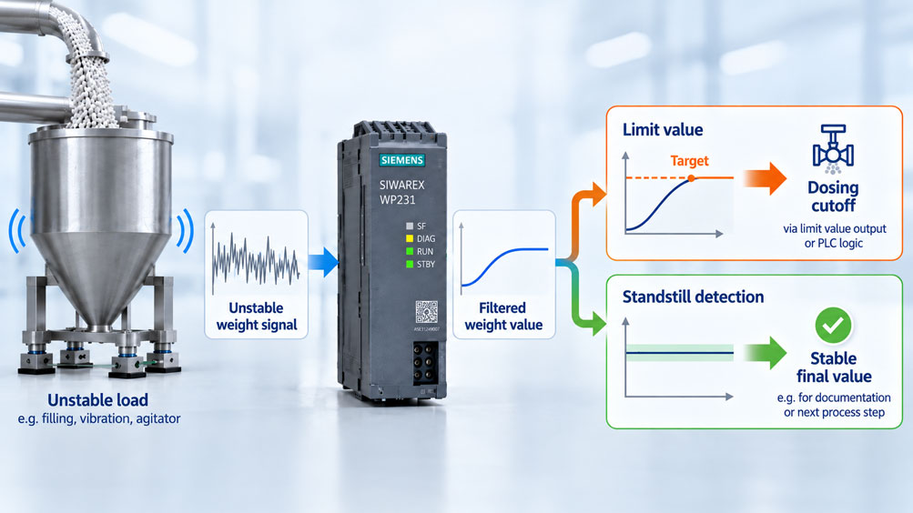
During filling, a scale indicates 497 kg, 503 kg, 499 kg and shortly afterwards 505 kg again. The obvious reaction is often: increase the filtering.
This does indeed make the display more stable. At the same time, however, the scale responds more slowly to an actual change in weight. If the weight value is used for a cutoff function, this delay can cause the material supply to be stopped too late.
With the SIWAREX WP231, three different tasks must therefore be clearly distinguished: The weight signal must be filtered appropriately, a sufficiently stable condition must be detected and any cutoff logic derived from it must respond quickly enough to the process.
The cause of an unstable weight signal does not necessarily lie in the electronics. Material impact, agitators, pumps, screw conveyors, rigid pipework, vibrations of the machine frame or unfavorable load-cell installation can transfer real forces to the scale.
A digital filter can reduce these movements in the signal. However, it does not eliminate the mechanical cause.
The SIWAREX WP231 provides several tools for this purpose. The module features an adjustable low-pass filter, an averaging filter, standstill monitoring, freely configurable weight limit values and a trace function for recording the signal profile.
The important point is not to configure these functions independently for the strongest possible damping.
A heavily filtered weight value can appear stable even though the actual load is still oscillating. An extremely narrow standstill range, on the other hand, can mean that the scale practically never reports standstill under normal operating conditions. A cutoff point that is detected too late can in turn cause overdosing.
There is also an important distinction to be made: The WP231 is weighing electronics for non-automatic scales, vessel weighing, force measurement and level monitoring. It provides limit values and inputs/outputs, but it does not include a complete integrated dosing control system with automatic material-in-flight correction.
A simple cutoff function can be implemented via the PLC or through appropriately assigned limit-value signals. For automated dosing and filling processes with integrated dosing functions, however, the SIWAREX WP251 is intended.
The key point is: With an unstable scale, the digital filter must not be optimized in isolation. Mechanics, low-pass filtering, averaging, standstill, limit values and cutoff logic must be considered as one interconnected dynamic system.
Table of Contents
- What task does the SIWAREX WP231 perform?
- What causes an unstable weight value?
- Why mechanical causes should be checked first
- Correctly distinguish measuring rate from filtering
- How does the low-pass filter work?
- What is the significance of the filter order?
- When is the averaging filter useful?
- Do not combine low-pass and averaging filters more strongly than necessary
- Configure filters using trace data rather than the display alone
- How does the WP231 detect standstill?
- Correctly select standstill range and standstill time
- What does standstill waiting time mean?
- Correctly use limit values 1 and 2
- Implement a simple dosing cutoff with the WP231
- Why material in flight must be taken into account
- Why filtering can shift the cutoff point
- When is the SIWAREX WP251 the better choice?
- Practical commissioning sequence
- Systematically diagnose typical faults
- Suitable SIWAREX components from ICS Schneider
- Conclusion
- Frequently asked questions about SIWAREX WP231 with unstable loads
1. What task does the SIWAREX WP231 perform?
The SIWAREX WP231 is a single-channel weighing module for the SIMATIC S7-1200 and can alternatively also be operated without a SIMATIC CPU.
It supplies connected strain-gauge load cells, measures their very small bridge signal and converts it into a usable weight value.
Typical applications include vessel and platform scales, level monitoring, force measurement and other non-automatic weighing tasks.
The WP231 has an internal resolution of up to ±4 million divisions and operates at a measuring rate of 100 or 120 Hz.
Available interfaces include the SIMATIC S7-1200 system bus, Ethernet with Modbus TCP/IP and SIWATOOL, as well as RS485 with Modbus RTU.
Four digital inputs, four digital outputs and one analog output are also available.
For an unstable scale, the digital filters, standstill detection, limit-value monitoring and trace function are particularly relevant.
2. What causes an unstable weight value?
A fluctuating weight value can have electrical, mechanical or process-related causes.
Electrical interference can, for example, be caused by unfavorable cable routing, inadequate shielding, potential differences or interference on the load-cell cable.
In many practical applications, however, the signal is unstable because genuinely changing forces are acting on the load cells.
An agitator continuously changes the force distribution in the vessel. A screw conveyor can transfer vibrations into the structure. Freely falling material generates additional dynamic forces. Pumps and motors can cause periodic vibrations.
Connected pipework can also influence the weighing signal. A rigid pipe can change due to temperature or pressure and thereby transfer additional forces to the weighed vessel.
The weighing electronics cannot distinguish whether a measured force comes from the actual product weight or from an unwanted mechanical load.
The first task is therefore to understand the cause of the signal movement.
3. Why mechanical causes should be checked first
Strong digital damping is not a substitute for poor mechanical design.
If, for example, a pipe transfers a varying force of several kilograms to a vessel, the electronics can smooth this influence. The static measurement error, however, remains.
The same applies to a load cell that is installed under mechanical stress or has to absorb transverse forces for which it was not designed.
Before optimizing the filters, supports, load-cell installation, pipe connections, vibration sources, cables and grounding should therefore be checked.
| Observation | Possible mechanical cause | Initial check |
|---|---|---|
| Periodic weight fluctuation | Agitator, motor or pump | Compare the fluctuation frequency with machine operation |
| Weight changes when a screw conveyor is switched on | Mechanical force transmission | Mechanically decouple conveying equipment and vessel |
| Zero point changes with temperature | Pipe forces or thermal stress | Check flexible connections and mounting |
| Short high peaks during filling | Material impact | Investigate drop height and inlet position |
| Signal remains noisy even when the system is completely at rest | Electrical system, shielding or load-cell signal | Check raw signal and load-cell signal in mV |
Only after mechanically avoidable influences have been reduced should the filtering be matched to the remaining process dynamics.
4. Correctly distinguish measuring rate from filtering
The WP231 continuously generates new measured values internally. However, a high measuring rate does not mean that every one of these values should be passed to the control system without filtering.
Fast measurement acquisition is initially advantageous because it allows the electronics to detect rapid changes as well.
The digital filter then determines which time-dependent signal components remain in the usable weight value.
This creates a fundamental trade-off.
A very fast scale responds almost immediately to actual weight changes, but it also shows vibrations more clearly.
A heavily damped scale provides a stable value, but requires more time to follow an actual change in weight.
The optimum setting therefore does not depend solely on how stable the display should appear.
The decisive factor is how quickly the application must respond to an actual load change.
5. How does the low-pass filter work?
The SIWAREX WP231 features a digitally adjustable low-pass filter.
Its purpose is to attenuate rapid signal changes and higher-frequency disturbances more strongly than slower weight changes.
The most important parameter is the cutoff frequency.
For the WP231 operating filter, a cutoff frequency between 0.05 and 20 Hz can be configured. A value of 0 switches the filter off.
A high cutoff frequency allows faster signal changes to pass through. The scale therefore responds more quickly, but appears more unstable.
A low cutoff frequency suppresses rapid fluctuations more strongly. The display becomes more stable, but the response time also increases.
Siemens explicitly illustrates this relationship using 5 Hz and 0.5 Hz as examples: 5 Hz results in a relatively fast response, while 0.5 Hz makes the scale significantly slower.
The cutoff frequency should therefore not be selected according to the principle “the lower, the better”.
6. What is the significance of the filter order?
In addition to the cutoff frequency, the order of the low-pass filter can also be configured on the WP231.
Filter orders 2, 4, 6, 8 and 10 are available.
A higher order provides stronger separation between low- and high-frequency signal components.
This can suppress an interfering vibration more effectively.
However, the same rule applies here: Stronger filtering changes the time response of the scale.
Cutoff frequency and filter order should therefore be considered together.
It is usually not advisable to select both an extremely low cutoff frequency and the highest possible filter order merely to obtain a completely stable display.
The resulting weight value may then respond too slowly for a fast cutoff function.
7. When is the averaging filter useful?
In addition to the low-pass filter, the WP231 includes an averaging filter.
It calculates the weight value from several consecutively acquired individual values.
The filter depth can be set between 0 and 250.
According to Siemens, the weight values used for this purpose are generated at intervals of 10 ms. With a filter depth of 10, ten values are therefore included in the moving average.
This corresponds to a time window of approximately 100 ms.
With a depth of 50, approximately 500 ms of measurement history is taken into account; with a depth of 100, approximately one second.
The averaging filter is particularly suitable for reducing random fluctuations.
However, increasing the filter depth also results in a slower response to actual changes.
For a weight-based cutoff function, it should therefore always be checked how far the filtered value lags behind the actual process.
8. Do not combine low-pass and averaging filters more strongly than necessary
Because the WP231 provides both low-pass filtering and averaging, there is a temptation to configure both filters as strongly as possible.
This usually produces a very stable display.
For process control, however, the result may be unfavorable.
A material flow continuously increases the actual vessel weight. If the filtering system introduces significant delay, the control system may still indicate 490 kg even though 500 kg is already present in the vessel.
In this case, the scale is not inaccurate in the static sense. The displayed signal is simply lagging behind in time.
This distinction is especially important for cutoff processes.
The filters should therefore only be set as strongly as necessary for reliable signal evaluation.
9. Configure filters using trace data rather than the display alone
The WP231 includes a trace function for continuous recording of measured values.
Trace recording can be performed with cycles including 10 ms, 100 ms, one second or ten seconds.
The faster recording options are particularly useful for filter optimization.
The WP231 also provides internal unfiltered and filtered digital values.
This makes it much easier to assess what is actually happening in the signal than simply observing the number displayed on an HMI.
A typical commissioning test is to record a defined weight change or an actual filling process.
The raw signal, filtered signal and relevant process condition are then compared.
This makes it possible to determine whether the filter is mainly removing noise or is already masking relevant process dynamics.
The WP231 also includes a second low-pass filter as a commissioning aid. This allows alternative filter settings to be evaluated for test purposes without optimizing the operating filter purely by trial and error.
10. How does the WP231 detect standstill?
Standstill detection serves a different purpose from the digital filter.
Its purpose is to determine whether the scale has reached a sufficiently stable equilibrium condition.
For this purpose, the WP231 evaluates how strongly the weight value changes within a defined period.
Standstill is present when the weight remains within the configured standstill range throughout the configured standstill time.
The standstill range is specified in scale divisions or d.
The standstill time defines how long this condition must be maintained.
The WP231 provides standstill as status information.
Internally, this status is used particularly for weighing-related functions such as zeroing, taring and, in legal-for-trade applications, the corresponding registration functions.
In a PLC application, the status can additionally be used, for example, to accept a final value after a filling process only once the scale has actually settled sufficiently.
11. Correctly select standstill range and standstill time
A very small standstill range may initially appear particularly accurate.
On a real industrial scale, however, a setting that is too narrow can cause the standstill status to be reached only rarely because of normal residual mechanical movement.
A very large range, by contrast, may report standstill even though the weight is still fluctuating significantly.
The same applies to the time setting.
A very short standstill time responds quickly but can incorrectly evaluate brief periods of low movement within an ongoing oscillation as stable.
A long standstill time increases the robustness of stability detection but delays every process step that waits for this status.
The parameters should therefore be derived from the actual variation of the settled scale and the permissible process deviation.
| Parameter change | Effect | Possible risk |
|---|---|---|
| Smaller standstill range | Stricter stability requirement | Standstill is rarely reached with normal residual movement |
| Larger standstill range | Standstill is reached more easily | A scale that is still moving may be considered stable |
| Shorter standstill time | Faster status indication | Brief periods of low movement may be interpreted as standstill |
| Longer standstill time | More robust stability evaluation | Slower process release |
The WP231 allows standstill times from 10 ms to 10,000 ms. This wide setting range alone shows that there is no universal value suitable for every scale.
12. What does standstill waiting time mean?
The standstill waiting time must not be confused with the actual standstill time.
It describes the maximum time for which the module waits for standstill when executing a command that requires a stable condition.
Examples include zeroing, taring or registering.
If standstill is not reached within this period, the corresponding command cannot be executed as intended and a technology message is generated.
With a standstill waiting time of 0, a standstill-dependent command is rejected immediately if no standstill condition exists at the time of the command.
For external dosing logic, it should therefore not be assumed that standstill waiting time automatically represents a process settling or post-dosing period.
These are different functions.
13. Correctly use limit values 1 and 2
The WP231 provides two freely configurable weight limit values as well as an additional empty limit value.
Limit values 1 and 2 can refer to gross or net weight and can be configured either as absolute values or relative to the weighing range.
Separate switch-on and switch-off points are available for each limit value.
This allows a hysteresis to be created.
Separate delay times can also be defined for switching on and switching off.
A limit-value status therefore changes only if the configured condition is still met after the delay time has elapsed.
This is useful, for example, when individual short weight peaks should not immediately trigger a switching state.
The limit-value states are available as status bits and can be assigned to the digital outputs of the WP231 or processed further in the S7-1200.
14. Implement a simple dosing cutoff with the WP231
This means that the WP231 can also be used in simple filling applications where a conveyor, valve or pump must be switched off at a defined weight.
However, the function must be correctly classified.
The WP231 does not itself execute a complete automatic dosing algorithm with coarse flow, fine flow, material in flight and automatic material-in-flight correction.
A simple cutoff logic can, for example, be implemented in the S7-1200.
The control system reads the current weight value or a limit-value status and stops the material supply at the defined cutoff point.
Alternatively, an appropriately configured limit-value status can be assigned to a digital output, provided that the system and safety concept allow this.
For any such solution, however, filter delay, PLC cycle time, output response, actuator time and material in flight must be considered together.
15. Why material in flight must be taken into account
A material flow does not normally stop at the exact moment the electrical cutoff signal is generated.
A screw conveyor has mechanical run-down time. Material is already traveling through a drop pipe toward the vessel. A valve requires a certain closing time.
This quantity of material still enters the scale after the cutoff signal.
If the system is switched off only at exactly 500 kg, the stable final value may therefore be 503 kg, for example.
This effect is primarily a characteristic of the process and is independent of the measuring instrument.
For a simple PLC solution, the cutoff point may therefore need to be placed before the actual target value.
The required amount of advance cutoff should be determined from actual filling cycles.
If the material in flight varies significantly, a static cutoff point and simple limit-value logic may no longer be sufficient.
16. Why filtering can shift the cutoff point
In addition to mechanical material in flight, there is also the time delay introduced by measured-value filtering.
A more heavily filtered weight value follows an increasing actual weight more slowly.
The control system therefore detects the cutoff value later.
With a low material flow rate, this effect may be insignificant.
With a high mass flow rate, however, even a delay of a few hundred milliseconds can correspond to a significant additional quantity of material.
Example: At a material flow rate of 20 kg/s, an additional delay of 200 ms theoretically already corresponds to 4 kg of material.
This simple calculation demonstrates why filter parameters should never be selected solely according to how stable the display appears.
The actual cutoff test under production conditions is decisive.
17. When is the SIWAREX WP251 the better choice?
As soon as the scale is not only required to provide a weight value but must independently and accurately control a recurring dosing or filling process, the SIWAREX WP251 is the more suitable device class.
Siemens designed the WP251 specifically for dosing, filling and automatic weighing tasks.
It includes corresponding integrated process functions and can, among other things, automatically correct cutoff points.
This allows it to account much more effectively for typical effects such as reproducible material in flight within a dosing concept.
The WP231, by contrast, is particularly suitable when a vessel or platform scale must be measured reliably and the actual sequence control is programmed project-specifically in the PLC.
Device selection should therefore not be based only on resolution and measuring rate.
The decisive question is whether only a precise weight value with limit values is required or whether a complete automatic dosing function is needed.
18. Practical commissioning sequence
A sensible configuration does not begin with maximum filtering.
The scale should first be mechanically installed and adjusted correctly.
The signal profile is then recorded with low or defined filtering.
This makes it possible to identify which fluctuations are actually present and what frequency or characteristics they have.
The low-pass filter is then configured so that interfering signal components are reduced sufficiently without unnecessarily impairing the required response speed.
The filter order is increased only as far as necessary for the application.
The averaging filter can then be used to further reduce any remaining random fluctuations.
Only after this should the standstill range be defined on the basis of the actual signal band of a truly settled scale.
The standstill time is selected so that short random periods of low movement are not incorrectly interpreted as a stable final condition.
For a cutoff function, actual filling cycles are then recorded. The target value, detected cutoff point, actual cutoff signal and later settled final value are particularly important.
On this basis, filtering and cutoff advance can be optimized together.
19. Systematically diagnose typical faults
| Observation | Possible cause | Recommended check |
|---|---|---|
| Display is stable, but cutoff regularly occurs too late | Filtering too strong | Compare raw signal and filtered value in the trace |
| Standstill is practically never reached | Standstill range too narrow, time too long or actual mechanics too unstable | Determine the signal band in the fully settled state |
| Standstill is reported while slight movement is still present | Standstill range too large or standstill time too short | Tighten the parameters and verify using trace data |
| Limit value switches on individual weight peaks | Insufficient hysteresis or delay | Check switch-on/switch-off points and limit-value delay |
| Final weight is always above the target value | Material in flight and/or filter delay | Record cutoff time and stable final value |
| Final weight varies from batch to batch | Variable material flow or variable material in flight | Investigate the conveying process rather than only filter parameters |
| Weight changes when a motor starts without any material change | Mechanical or electrical coupling | Check raw signal, mechanical connection and shielding |
| WP231 is insufficient for the required automatic dosing function | Device class is not designed for a dosing algorithm | Consider SIWAREX WP251 as a dosing solution |
20. Suitable SIWAREX components from ICS Schneider
ICS Schneider Messtechnik offers SIWAREX weighing electronics, load cells and accessories for vessel, platform, dosing and process scales. An overview can be found under Weighing Technology and Siemens Process Instrumentation.
20.1 SIWAREX WP231
The SIWAREX WP231 is a single-channel weighing module for SIMATIC S7-1200 or stand-alone operation.
It provides a measuring rate of 100/120 Hz, an internal resolution of up to ±4 million divisions and variably adjustable low-pass and averaging filters.
SIWATOOL can be used to commission, configure and diagnose the scale.
Trace, limit values, standstill status and the available digital and analog inputs/outputs make the WP231 particularly suitable for vessel, platform and simple process-integrated weighing applications.
20.2 SIWAREX DB for Detailed Load-Cell Diagnostics
In combination with the WP231, the SIWAREX DB can be used for digitization and detailed diagnostics of multiple connected load cells.
The junction box enables, among other things, wire-break and impedance monitoring as well as evaluation of the current load on individual load cells.
For unstable or asymmetrical vessel scales, individual-channel evaluation can be helpful for detecting unfavorable load distribution or mechanical abnormalities more quickly.
20.3 SIWAREX WP251 for Dosing and Filling Processes
The SIWAREX WP251 is specifically designed for dosing and filling processes.
It can independently control corresponding weighing processes and provides integrated functions for these applications.
These include automatic correction of cutoff points.
If high dosing accuracy, short cycle times and reproducible material in flight are key requirements, it should therefore be checked whether the WP251 represents a more suitable architecture than the WP231.
21. Conclusion
An unstable scale does not automatically become better simply by configuring the strongest possible digital filter.
With the SIWAREX WP231, low-pass cutoff frequency, filter order and averaging together determine how strongly the signal is stabilized and how quickly it can still respond to actual changes in weight.
A low cutoff frequency and a high filter order can significantly reduce strong mechanical fluctuations. At the same time, however, the weight signal becomes slower.
The averaging filter can additionally reduce random fluctuations, but at a high filter depth it also increases the time-related smoothing.
Standstill detection then becomes relevant for obtaining a stable final value. It does not simply evaluate whether the displayed value appears to change only slightly, but whether the weight remains within the defined standstill range throughout the specified standstill time.
For a simple filling application, the two WP231 limit values can be used for monitoring or as the basis for cutoff logic.
However, the cutoff function must not be considered independently of filter delay and material in flight.
A weight signal that lags behind the process by 200 ms can already correspond to a relevant additional product quantity at a high mass flow rate.
For reliable configuration, the following sequence therefore applies:
Check the mechanics → record the raw signal using Trace → configure the low-pass filter only as strongly as necessary → optimize the filter order → add averaging sparingly → derive the standstill range from actual residual movement → define the standstill time → configure limit values and hysteresis → record real cutoff cycles → correct material in flight and filter delay together.
If a complete automatic dosing or filling process with independent optimization of the cutoff points is required, the SIWAREX WP251 should be used or at least included in the device selection.
The most important practical principle is therefore: The most stable display is not automatically the best configuration. What matters is the best compromise between signal stability, response time and reproducible process behavior.
22. Frequently asked questions about SIWAREX WP231 with unstable loads
22.1 Which digital filters does the SIWAREX WP231 provide?
The WP231 provides an adjustable low-pass filter and a moving-average filter. A second low-pass filter is also available as a commissioning aid.
22.2 What range can be configured for the low-pass cutoff frequency?
The operating low-pass filter can be configured between 0.05 and 20 Hz. A value of 0 switches it off.
22.3 What does a lower cutoff frequency do?
It attenuates rapid signal changes more strongly and stabilizes the weight value, but at the same time increases the sluggishness of the scale.
22.4 Which filter orders are available?
The WP231 supports filter orders 2, 4, 6, 8 and 10. Filter effectiveness increases with higher order.
22.5 How high can the averaging-filter depth be set?
The filter depth can be set between 0 and 250 values.
22.6 Does a larger averaging depth automatically mean a better measurement?
No. It stabilizes the signal more strongly but also slows its response to an actual change in weight.
22.7 What does standstill mean on the WP231?
Standstill is present when the weight value remains within the configured standstill range throughout the configured standstill time.
22.8 In which unit is the standstill range specified?
The standstill range is specified in scale divisions or d.
22.9 What happens if the standstill range is configured too small?
The scale may continuously be considered unstable even though it is sufficiently settled in practical terms.
22.10 What happens if the standstill time is too short?
Brief periods of low movement during an ongoing oscillation can be detected too early as standstill.
22.11 What is the standstill waiting time?
It is the maximum waiting time for standstill for commands that require a stable condition, such as zeroing or taring.
22.12 Does the WP231 provide limit values?
Yes. Two freely configurable weight limit values and one empty limit value are available.
22.13 Can hysteresis be configured for a limit value?
Yes. Separate switch-on and switch-off points can be defined for limit values 1 and 2.
22.14 Can a limit value be delayed in time?
Yes. The WP231 allows separate delay times for switching the limit-value states on and off.
22.15 Can the WP231 stop a dosing process?
A simple weight-dependent cutoff can be implemented via limit-value status, digital output or S7-1200 logic. However, the WP231 is not a complete integrated dosing controller.
22.16 Why can overdosing occur despite a correct cutoff weight?
Possible causes include material in flight, actuator delay, PLC cycle time and the time delay of the filtered weight signal.
22.17 Can strong filtering increase overdosing?
Yes. If the displayed or evaluated weight value lags behind the actual weight, the cutoff point is detected later.
22.18 How do I find a suitable filter setting?
The best approach is to record the actual weight profile using Trace and compare the unfiltered signal with the filtered signal. Filtering should only be increased as far as necessary for stable process evaluation.
22.19 When should the WP251 be used instead of the WP231?
If a true automatic dosing or filling process with integrated process control, high dynamics and automatic correction of cutoff points is required, the SIWAREX WP251 is intended for this purpose.
22.20 What information does ICS Schneider require for configuration or device selection?
Useful information includes the weighing range, number and type of load cells, scale division, required accuracy, type and magnitude of load fluctuations, material flow, target weight, required cycle time, existing conveying equipment, expected material in flight, integration into the S7-1200 or other control systems, and whether the application only requires weighing or actual automatic dosing or filling.