


Stable 24 V DC is often already available in a control cabinet. Nevertheless, it can still be useful to supply a sensor, transmitter or remote electronic module via an additional DC/DC converter.
The reason is not always a different output voltage. A DC/DC converter can, for example, convert an existing 24 V supply into 24 V again. The decisive question is then whether input and output remain electrically connected or are galvanically isolated from one another.
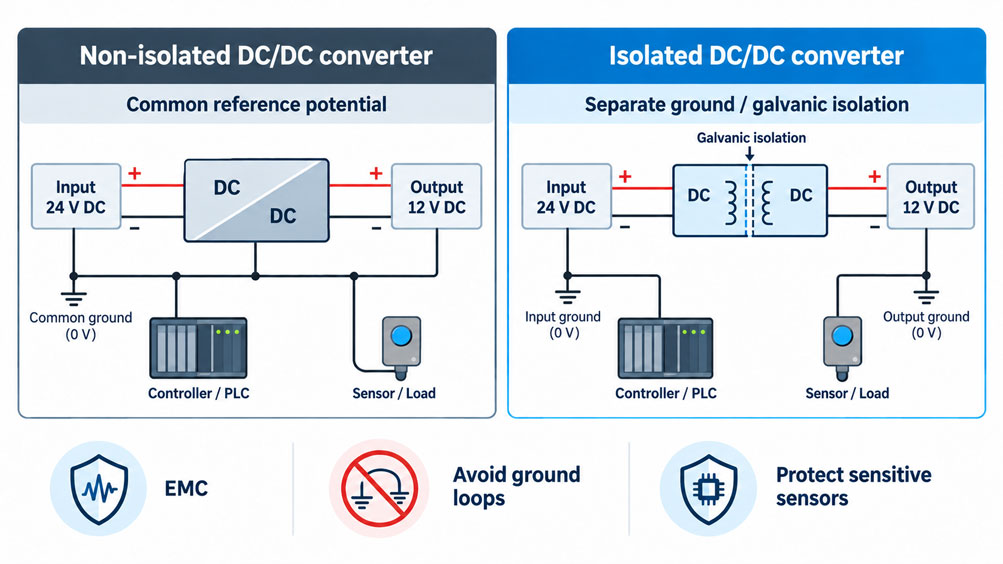
With a non-isolated DC/DC converter, input and output continue to share a common electrical reference. In many cases, input minus and output minus are directly connected. The converter changes or stabilizes the voltage, but it does not create a new potential domain.
An isolated DC/DC converter, by contrast, has no direct conductive connection between the input and output circuits. Its output side can therefore initially float relative to the input side and, if required, be assigned its own reference point.
This characteristic is often more important for industrial measurement and control circuits than the voltage conversion itself.
A remote sensor, for example, may have a different ground potential from the central PLC due to its mounting arrangement, cable shield, another power supply or connected evaluation electronics. If these potentials are unintentionally connected, equalizing currents, interference and difficult-to-trace measurement errors can occur.
On the other hand, galvanic isolation is not automatically the better solution. If all components intentionally use the same 0 V reference, are located close together and no functional or safety-related isolation is required, a non-isolated converter can be simpler, more powerful and more economical.
An isolated converter also does not automatically solve every EMC problem. High-frequency interference can still couple between the circuits via parasitic capacitances of the isolation barrier, cable shields or other electrical connections.
The key point is: The decision between an isolated and a non-isolated DC/DC converter must be based on the complete circuit architecture. Power supply, signal path, ground reference, protective conductor, shielding, power, inrush current and cable losses must be considered together.
Table of Contents
- What does a DC/DC converter do?
- What is the difference between isolated and non-isolated converters?
- What does a separate potential domain mean?
- When is galvanic isolation useful?
- When is a non-isolated DC/DC converter sufficient?
- Why can converting 24 V to 24 V be useful?
- Why the power supply alone does not create complete isolation
- Correctly assessing 2-wire and 4–20 mA circuits
- Do not confuse 0 V, PE and functional earth
- Include shields and equipotential bonding in the concept
- Distinguish isolation voltage from safety isolation
- Correctly size output power and input current
- Consider inrush current and capacitive loads
- Correctly assess cable losses for remote sensors
- Why galvanic isolation does not automatically eliminate EMC problems
- Correctly plan short-circuit, overload and fuse protection
- Structure multiple isolated sensor groups sensibly
- Systematically diagnose typical faults
- Isolated or non-isolated: practical selection guide
- Suitable DC/DC converters from ICS Schneider
- Conclusion
- Frequently asked questions about isolated DC/DC converters
1. What does a DC/DC converter do?
A DC/DC converter takes an existing DC voltage and generates a defined DC voltage for a downstream load.
Depending on the circuit topology, the output voltage may be lower, higher or, with certain topologies, either above or below the input voltage.
Typical applications in industrial systems include supplying sensors, transmitters, PLC modules, displays, communication modules and auxiliary electronic devices.
Selection therefore usually begins with the input and output voltage. However, this alone is not sufficient for a complete design.
Output current, power, efficiency, input-voltage range, ripple, load dynamics, temperature, protection functions and, where applicable, galvanic isolation must also be considered.
The last point in particular fundamentally changes the electrical structure of the circuit.
2. What is the difference between isolated and non-isolated converters?
With a non-isolated DC/DC converter, there is a conductive connection between the input and output sides.
In simplified form, the following typically applies:
0 V input = 0 V output
The output therefore remains part of the same potential system.
With an isolated converter, energy is transferred across an isolation barrier. Under intended operating conditions, there is no direct galvanic connection between the input and output.
This creates a separate supply circuit on the output side.
| Characteristic | Non-isolated DC/DC converter | Isolated DC/DC converter |
|---|---|---|
| Direct galvanic connection | Yes | No |
| Common 0 V reference | Usually yes | Not necessarily |
| Independent output potential | No | Yes |
| Interrupt ground loops | No | Generally possible |
| Convert voltage | Yes | Yes |
| 24 V to 24 V useful | Only for special regulation or decoupling purposes | Yes, for galvanic isolation |
Neither version is fundamentally technically superior. The decisive factor is which electrical function is required in the overall system.
3. What does a separate potential domain mean?
An isolated output initially has no fixed electrical reference to the input side.
The output terminals may, for example, be designated +24 V and 0 V. However, this 0 V is not automatically the same potential as the 0 V of the input power supply.
The output side can therefore initially float.
Depending on the system concept, a deliberate connection to PE, functional earth or another potential can subsequently be established. This does not necessarily eliminate the galvanic isolation from the input, but the output is then no longer floating relative to this reference point.
For this reason, the reference point of an isolated circuit should be deliberately planned and documented.
An output that has intentionally been connected to a defined potential at one point should not accidentally be connected a second time at a remote location to a different potential.
4. When is galvanic isolation useful?
Galvanic isolation is particularly useful when sensor and control circuits have, or can have, different electrical reference potentials.
A typical example is a sensor installed on a remote machine. The PLC is located in the main control cabinet, while the sensor housing or connected plant components are grounded locally.
Potential differences can occur between these two locations. If the circuits are connected through several conductive paths, equalizing currents can flow.
Other typical applications include sensitive analog measurement technology, distributed control systems, different control-cabinet sections, battery and vehicle electrical systems, and measuring circuits that need to be decoupled from strongly switching loads.
Galvanic isolation can also be useful when a fault in one supply circuit should not be transferred directly to another circuit.
Whether the isolation is required only for functional separation or must additionally provide a defined safety function must be assessed separately.
5. When is a non-isolated DC/DC converter sufficient?
An additional isolation barrier is not required in every application.
Within a compact control cabinet, for example, a common 24 V / 0 V reference may deliberately be used for the PLC, sensors and auxiliary electronics.
If only a regulated 12 V supply must be generated from 24 V and there are no problematic potential differences, a non-isolated DC/DC converter can be the technically simpler solution.
A non-isolated architecture can also be advantageous at higher power levels if no isolation requirement exists.
Installing galvanic isolation merely “to be safe” without defining its purpose in the circuit diagram does not automatically create a better system.
It can result in additional cost, power loss, installation space and EMC effort.
6. Why can converting 24 V to 24 V be useful?
With an isolated DC/DC converter, the output voltage does not have to differ from the input voltage.
A typical supply concept may be:
24 V main supply → isolated DC/DC converter → 24 V sensor supply
The two sides are then electrically isolated despite having the same nominal voltage.
The sensor circuit receives its own 0 V reference and is not automatically connected to the 0 V of the main circuit.
This can be useful, for example, when a central supply simultaneously powers relays, solenoid valves, contactors and other interference-generating loads, while a sensitive measurement group should have its own separate reference.
The same output voltage therefore does not mean that the converter is unnecessary. In this case, its primary function may be isolation rather than voltage conversion.
7. Why the power supply alone does not create complete isolation
One of the most common design errors is to consider only the supply voltage.
An isolated DC/DC converter initially isolates only its own input and output.
If a signal line then directly reconnects the two potential domains, the complete assembly is no longer fully galvanically isolated.
A sensor can, for example, be powered from an isolated 24 V converter while its voltage output is connected to a non-isolated PLC analog input.
If signal ground and output minus are directly connected, a galvanic path is re-established through this connection.
For a truly isolated measurement island, all connections between the potential domains must therefore be considered.
| Possible connection path | Can it bypass the isolation? | What must be checked? |
|---|---|---|
| Power supply line | Yes | Isolated or non-isolated DC/DC converter |
| Analog signal | Yes | Galvanically isolated analog input or signal isolator |
| Digital communication | Yes | Isolated transceiver / communication interface |
| Cable shield | Depends on connection concept | Check shielding and EMC concept |
| PE / functional earth | Yes, or defines a reference potential | Check grounding concept |
| Sensor or machine housing | Possible | Consider mechanical and electrical installation |
Galvanic isolation is therefore always a property of the complete connection and not merely of one individual component.
8. Correctly assessing 2-wire and 4–20 mA circuits
This consideration is particularly important in 4–20 mA measuring circuits because power supply and measurement signal are often closely linked.
A 2-wire transmitter is powered from the same current loop through which it transmits its measured value.
If such a measuring point is to be galvanically isolated from the control system, an isolated DC/DC converter alone is not necessarily sufficient.
The complete loop must be considered: supply voltage, transmitter, analog input, any existing isolating power supply, shielding and ground references.
In many applications, a galvanically isolated repeater power supply or signal isolator therefore also provides electrical isolation of the measurement signal.
With 3- or 4-wire sensors, supply and signal can form separate paths. In this case, each path must be checked individually to determine whether the required isolation is maintained.
9. Do not confuse 0 V, PE and functional earth
In circuit diagrams, different reference potentials are often simplified and referred to as “ground”. Technically, however, they can perform different functions.
The 0 V potential of a 24 V supply is initially the electrical reference point of that DC circuit.
PE provides protection against hazardous touch voltages and forms part of the protective concept of the system.
Functional earth, or FE, can instead be used specifically for EMC and functional purposes.
Whether and at which point 0 V is connected to PE or FE depends on the complete supply concept and the applicable requirements.
With an isolated output supply, it should therefore not automatically be assumed that output minus must always remain unearthed or must always be earthed.
This decision belongs in the documented grounding and EMC concept of the system.
10. Include shields and equipotential bonding in the concept
A cable shield is not the same as the signal return conductor.
Its primary purpose is to conduct electromagnetic interference away or reduce its coupling into the cable.
Depending on the signal type, frequency range and system concept, the shield may be connected at one end, at both ends or through special components.
A blanket rule for every sensor cable would therefore not be appropriate.
One important point remains: A shield connected conductively at both ends can create an additional electrical path between two parts of the installation.
If a power supply has deliberately been galvanically isolated, it must therefore be checked which additional connections exist through the shield, housing and equipotential bonding.
Even the best DC/DC converter selection cannot compensate for a contradictory grounding and shielding concept.
11. Distinguish isolation voltage from safety isolation
An isolation voltage is often specified for isolated DC/DC converters.
This value describes a defined test of the insulation barrier between input and output.
It must not be interpreted without further assessment as the permissible continuous working voltage between the two sides.
Likewise, a high test voltage does not automatically mean that a converter is suitable for every safety-related isolation requirement.
Depending on the application, a distinction is made, among other things, between functional insulation, basic insulation and reinforced insulation.
| Type of insulation | Basic function | Typical significance |
|---|---|---|
| Functional insulation | Electrical separation required for device operation | For example, potential separation and interruption of ground loops |
| Basic insulation | Basic protection against electric shock | Part of a safety concept assessed according to applicable standards |
| Reinforced insulation | Enhanced insulation in accordance with an extended protection concept | Applications with correspondingly higher safety requirements |
The required version depends on working voltage, overvoltage category, pollution degree, application, product standard and required protective measure.
SELV or PELV is also not created merely because any DC/DC converter has galvanic isolation. The converter and the complete system must meet the corresponding requirements.
12. Correctly size output power and input current
After defining the potential structure, the electrical power requirements must be considered.
The required output power is calculated from the output voltage and maximum load current:
Pout = Uout × Iout
A 24 V sensor circuit with a maximum current of 0.8 A therefore requires at least:
Pout = 24 V × 0.8 A = 19.2 W
The DC/DC converter should not be selected solely on the basis of this nominal operating point. Inrush currents, reserve capacity, ambient temperature and possible derating curves must also be taken into account.
The input current can also be significantly higher than a simple consideration of the output side might suggest.
In simplified form:
Iin ≈ Pout / (Uin × η)
where η is the efficiency of the converter.
For the fuse, cable and upstream power supply, the unfavorable operating point with low input voltage and high output power is particularly relevant.
13. Consider inrush current and capacitive loads
The rated current of a sensor or control device does not necessarily describe its current consumption during switch-on.
Electronic devices often contain input capacitors that must first be charged when power is applied.
If several devices are switched on simultaneously from one DC/DC converter, a significantly higher short-term load can therefore occur.
The DC/DC converter itself can also draw a current pulse from the upstream supply during switch-on due to its input capacitance.
The actual magnitude depends strongly on the converter, load, input voltage and switch-on circuitry and must therefore not be inferred solely from the rated current.
For critical applications, data-sheet specifications for inrush current, current limiting, soft start and capacitive load should be considered.
A converter whose rated power exactly matches the calculated continuous load may otherwise repeatedly shut down during start-up or cause the supply voltage to collapse.
14. Correctly assess cable losses for remote sensors
With long sensor cables, part of the supply voltage is lost across the conductor resistance.
For a two-wire supply with the same conductor cross-section for the outgoing and return path, the voltage drop can be calculated in simplified form using the total loop resistance:
ΔU = I × Rcable
The higher the current and cable length and the smaller the conductor cross-section, the greater the voltage drop.
A sensor therefore does not simply require a nominal “24 V”. What matters is the voltage actually present at its terminals under maximum load.
In certain applications, a DC/DC converter located close to the load can help generate a stable local sensor supply from a fluctuating or higher distribution voltage.
However, it cannot compensate for an input voltage that lies outside its permissible input-voltage range.
The cable calculation must therefore be performed together with the minimum input voltage of the converter and the maximum load current.
15. Why galvanic isolation does not automatically eliminate EMC problems
Galvanic isolation interrupts the direct conductive path between two circuits.
However, this does not mean that there is no high-frequency coupling between the two sides.
In a real isolated converter, parasitic capacitances exist between the primary and secondary sides. Fast switching edges can transfer common-mode currents through these capacitances.
There is also conducted interference on the input and output sides as well as possible coupling through cables, shields and housings.
An isolated converter can therefore interrupt ground loops very effectively, but it must still be suitable for the application in terms of ripple, switching frequency, conducted emissions and immunity.
With sensitive analog measurement technology, suitable filtering or spatial separation may additionally be required.
Galvanic isolation and good EMC performance are therefore related, but they are not identical characteristics.
16. Correctly plan short-circuit, overload and fuse protection
A DC/DC converter should not only be considered under normal operating conditions.
A short circuit on the sensor side, for example, must not cause cables to be thermally overloaded or an upstream control circuit to collapse uncontrollably.
Many industrial converters include internal short-circuit and overload protection functions.
However, these do not automatically replace the necessary protection of supply cables and circuits.
The upstream fuse must be compatible with input current, cable, inrush behavior and the manufacturer’s specifications.
On the output side, it must be checked whether the converter’s current limiting is even capable of reliably tripping a downstream fuse.
Particularly with electronically current-limited power supplies, the available short-circuit current can be significantly lower than with conventional power supplies.
The protective device and the power supply must therefore be designed as a coordinated combination.
17. Structure multiple isolated sensor groups sensibly
A single galvanically isolated supply for all sensors is not necessarily the optimum architecture.
If several spatially or functionally separate measuring groups are connected to the same isolated output, they again share a common secondary reference.
Common return currents and coupling can therefore occur again between these loads.
For particularly sensitive or widely distributed measuring points, it can therefore be useful to establish several separate supply groups.
However, isolation should not be subdivided arbitrarily. Every additional converter increases installation space, cost, power loss and diagnostic effort.
A sensible structure is based on functional groups, spatial distribution, signal sensitivity and possible common-cause failures.
18. Systematically diagnose typical faults
| Observation | Possible cause | Recommended check |
|---|---|---|
| Sensor value changes when valves or contactors switch | Common supply, ground shift or EMC coupling | Measure supply and ground potentials during the switching event |
| Isolated converter installed, but ground loop still exists | Signal, shield or housing reconnects the two potential domains | Check all galvanic connection paths |
| Sensor works in the control cabinet but not at the remote installation point | Cable voltage drop | Measure voltage directly at the sensor terminals under load |
| DC/DC converter repeatedly restarts | Inrush current, capacitive load or overload | Record start-up current and output voltage over time |
| 24 V output collapses under high load | Converter overloaded or input voltage too low | Measure input voltage, output voltage and load current simultaneously |
| Measurement signal shows high-frequency noise despite isolation | Capacitive common-mode coupling or switching interference | Investigate EMC path, filtering, shielding and cable routing |
| Isolated output unexpectedly has a potential relative to PE | Intentional or unintentional earth connection | Check the circuit diagram and actual connections to PE/FE |
| Output fuse does not trip during a short circuit | Electronic current limiting of the converter | Check the protection concept and available fault current |
19. Isolated or non-isolated: practical selection guide
The selection can be reduced to several central questions.
If input and output are intentionally intended to share the same 0 V reference and no isolation requirement exists, a non-isolated converter is often the appropriate choice.
If different ground potentials need to be separated, ground loops interrupted or an independent sensor supply created, an isolated version is the obvious option.
It must then be determined whether galvanic isolation is required only for functional purposes or whether it must also meet a defined safety-insulation class.
The conventional supply parameters are then considered: input-voltage range, output voltage, continuous current, peak load, efficiency, temperature, cooling and protection functions.
Finally, the complete system connection must be examined. An isolated DC/DC converter provides little benefit if another conductor directly reconnects the two potential domains.
20. Suitable DC/DC converters from ICS Schneider
ICS Schneider Messtechnik offers various DC/DC converters for industrial, mobile and measurement-related power-supply systems. An overview can be found under Power Supplies and DC/DC Converters.
20.1 ISD-25 Series – Galvanically Isolated DC/DC Supply
The ISD-25 Series is an example of a galvanically isolated industrial DC/DC converter.
The series provides 25 W output power and, depending on the model, is available with input-voltage ranges of 9.2 … 18 VDC, 19 … 36 VDC or 36 … 72 VDC.
Output versions with 5 VDC, 12 VDC or 24 VDC are available.
The specified I/O isolation is 1,500 VAC. The series also features an integrated EMI filter as well as protection functions against short circuit, overload and overvoltage.
For sensor circuits and smaller control circuits, the series can therefore be particularly useful when galvanic isolation is required in addition to voltage conversion.
However, the specified isolation test voltage alone should not be interpreted as proof of a particular normative safety-insulation class. For safety-related applications, the data sheet and the requirements of the specific installation must be assessed separately.
20.2 2218 Series – Voltage Conversion without Galvanic Isolation
The 2218 Series represents the alternative architecture without galvanic isolation.
Depending on the version, nominal input voltages of 24 VDC, 48 VDC or 60 VDC and output voltages of 5 VDC, 12 VDC or 24 VDC are available.
The series covers power ratings from 60 to 240 W and features short-circuit and electronic overload protection.
However, input and output are not galvanically isolated.
The series is therefore suitable for applications where defined DC voltage conversion is required but input and output are intentionally part of the same potential system.
20.3 Do not compare isolated and non-isolated converters only by power
When selecting a product, isolated and non-isolated converters should not be compared solely by wattage, voltage and price.
The required potential structure must be defined first.
Power, input-voltage range, output current, efficiency, ripple, temperature range, design and protection functions are then selected.
Especially for measuring and sensor circuits, a smaller isolated supply can be technically more appropriate than a significantly more powerful converter without galvanic isolation.
20.4 Application Engineering by ICS Schneider
For selecting a suitable DC/DC converter, relevant information includes the input voltage including minimum and maximum values, required output voltage, continuous and peak current, number and type of loads, cable lengths, ambient temperature and installation conditions.
It should also be described why galvanic isolation is required and which other electrical connections exist between the sensor side and the control side.
For safety-related isolation, the applicable standard, working voltage and required type of insulation are also needed.
21. Conclusion
The decision between an isolated and a non-isolated DC/DC converter is not merely a product-selection issue.
It determines whether two circuits electrically share the same reference point or initially form separate potential domains.
A non-isolated converter is suitable when input and output deliberately use the same ground reference and only a different or stabilized DC voltage is required.
An isolated converter, by contrast, is particularly useful when different ground potentials need to be separated, ground loops interrupted or sensitive sensor and measurement circuits established as a separate supply group.
However, isolating the power supply alone is not sufficient. Signal lines, communication interfaces, cable shields, protective conductors, functional earth and mechanical grounding connections can reconnect the two potential domains.
Likewise, a high isolation test voltage must not automatically be equated with safety isolation that is sufficient for the application. Functional, basic and reinforced insulation serve different purposes.
Once the potential structure has been defined, the power dimensioning follows. Continuous load, inrush current, capacitive loads, minimum input voltage, efficiency and temperature must be taken into account.
For remote sensors, voltage drop in the supply cable must also be considered.
From an EMC perspective, isolation is not a complete shield either. Parasitic capacitances can still couple high-frequency interference between the primary and secondary sides.
For reliable design, the following sequence therefore applies:
Define the potential structure → determine the required insulation type → check all signal and ground connections → define input and output voltage → determine continuous and peak load → consider start-up behavior → check cable losses → define EMC and shielding concept → size protective devices → select a suitable DC/DC converter.
The most important practical principle is therefore: Do not begin by asking which DC/DC converter should be used. First determine which electrical connection is actually permitted between the two sides.
22. Frequently asked questions about isolated DC/DC converters
22.1 What is an isolated DC/DC converter?
An isolated DC/DC converter transfers electrical energy between input and output without a direct galvanic connection between the two sides under intended operating conditions.
22.2 What is a non-isolated DC/DC converter?
With a non-isolated converter, input and output remain electrically connected. In many cases, both sides share a common minus or 0 V reference.
22.3 Is an isolated DC/DC converter always better?
No. If a common ground is explicitly required and no isolation requirement exists, a non-isolated version can be simpler and more economical.
22.4 Why convert 24 V to isolated 24 V?
This creates a separate output potential domain while maintaining the same nominal voltage. The primary function is then galvanic isolation rather than voltage conversion.
22.5 Does an isolated converter interrupt a ground loop?
It can interrupt the direct ground path through the power supply. Whether the entire ground loop actually disappears depends on whether additional connections exist through the signal, shield, PE or housing.
22.6 Is the output of an isolated converter automatically floating?
It is initially galvanically isolated from the input. If one output terminal is subsequently deliberately connected to PE, FE or another potential, the output side acquires a defined reference.
22.7 May I connect output minus to PE?
This depends on the grounding, EMC and safety concept of the installation. A universal recommendation is therefore not appropriate.
22.8 Does 1,500 VAC isolation mean 1,500 VAC continuous working voltage?
No. A specified isolation voltage is typically a defined test value. The permissible working voltage and normative insulation class must be determined separately from the technical and standards-related specifications.
22.9 Does a high isolation voltage automatically mean reinforced insulation?
No. The insulation class depends not only on test voltage but also on the design, creepage and clearance distances, working voltage and applicable standard.
22.10 Does an isolated DC/DC converter automatically make every output SELV?
No. For SELV or PELV, the requirements of the complete power-supply system and the applicable standards must be fulfilled.
22.11 Is an isolated converter sufficient for a galvanically isolated 4–20 mA circuit?
Not necessarily. If the measurement signal subsequently connects the two potential domains through a non-isolated analog input, the complete measurement circuit is no longer galvanically isolated.
22.12 Why can EMC interference still occur despite galvanic isolation?
Real isolation barriers have parasitic capacitances. Fast switching events can couple high-frequency common-mode currents between the two sides through these capacitances.
22.13 How large should a DC/DC converter be?
Output voltage and maximum continuous current form the basis. Inrush current, peak load, ambient temperature, derating and sufficient operating reserve must also be taken into account.
22.14 Why is the input current higher than expected?
The input must provide the output power plus the converter losses. At a lower input voltage, a higher input current is therefore required for the same power.
22.15 Can a capacitive load prevent start-up?
Yes. High charging-current peaks can activate the converter’s current limiting. Depending on the protection behavior, the output voltage may then rise slowly, collapse or repeatedly restart.
22.16 Can a DC/DC converter solve voltage drop in a long cable?
Local voltage conversion can be part of the solution. However, the converter input at the end of the cable must remain within its permissible input-voltage range even under maximum load.
22.17 How can a cable shield create an additional ground connection?
A shield conductively connected at both ends can create an additional electrical path between parts of the installation. It must therefore be taken into account in the potential and EMC concept.
22.18 Which ICS series is galvanically isolated?
The Mean Well ISD-25 Series has a specified I/O isolation of 1,500 VAC and is available with outputs of 5 VDC, 12 VDC or 24 VDC.
22.19 Which ICS converters are not galvanically isolated?
The 2218 DC/DC converters are examples of voltage converters without galvanic isolation between input and output.
22.20 What information does ICS Schneider require to select a suitable converter?
Useful information includes minimum and maximum input voltage, required output voltage, continuous and peak current, type and number of loads, cable length, ambient temperature, installation type, existing ground and earth connections, and whether functional or safety-related galvanic isolation is required.