


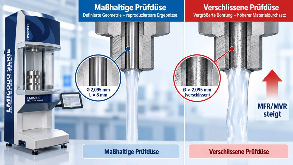
During a melt flow test, temperature, test load and test time are controlled very carefully. However, one much smaller component is easily underestimated: the test die at the lower end of the test barrel.
Its geometry is an integral part of the definition of the test. The polymer melt is forced through a precisely defined bore with a specified length. If this geometry changes due to wear, damage or unsuitable cleaning, the flow resistance also changes.
This can cause the same polymer to produce a different MFR or MVR under identical temperature and test-load conditions.
What makes this particularly critical is that such an error does not necessarily become apparent through strongly fluctuating results. A uniformly worn die can still produce highly repeatable values – but at a systematically shifted level.
Conversely, polymer residues or deposits can partially restrict the die. This increases the flow resistance and can reduce the measured melt flow. Wear and contamination can therefore even influence the result in opposite directions.
Especially with filled, reinforced or abrasive materials, not only the cleanliness but also the geometric condition of the test die must therefore be taken into account.
The same level of care is required after cleaning. Dynisco provides special cleaning tools and precision tools for the die bore. The bore must not be enlarged, scratched or otherwise altered while removing polymer residues.
The key point is: The test die is not simply a wear part outside the measurement chain, but part of the defined test geometry. Changes in bore diameter, length or surface condition can systematically influence MFR and MVR. Cleaning, dimensional inspection and timely replacement must therefore form part of the laboratory routine.
Table of Contents
- What is the function of the test die in melt flow testing?
- Why is the die geometry so important?
- How does a melt flow test die wear?
- What happens when the die bore becomes enlarged?
- Why is the die length also relevant?
- How do scratches and edges influence material flow?
- How does die wear affect MFR?
- How does die wear affect MVR?
- Why good repeatability can still produce incorrect results
- Correctly distinguish between wear and contamination
- How to clean the test die correctly
- Why filled plastics can place greater wear on the die
- How can die wear be checked?
- What role does the go/no-go gauge play?
- When can a reference material help with diagnostics?
- Why instrument calibration and die inspection belong together
- Correctly understanding ISO 1133 and ASTM D1238
- Systematically diagnose typical faults
- Suitable Dynisco testing equipment from ICS Schneider
- Conclusion
- Frequently asked questions about worn melt flow test dies
1. What is the function of the test die in melt flow testing?
In a melt flow indexer, a defined quantity of thermoplastic material is heated in a test barrel to the specified test temperature.
A piston applies force to the polymer melt through a defined test weight. The material can then leave the barrel only through the test die installed at its lower end.
The die therefore forms a precisely defined flow resistance.
For MFR, the mass of melt discharged within a defined period is determined and then converted to g/10 min.
For MVR, by contrast, the piston movement is used to determine the displaced melt volume and calculate the volumetric flow rate in cm³/10 min.
Although the two measured quantities therefore use different evaluation methods, the polymer flows through the same defined test die in both cases.
A change in die geometry can therefore influence both MFR and MVR.
2. Why is the die geometry so important?
In a conventional melt flow test, the standard die has a very precisely defined geometry.
For tests according to ISO 1133, a die with a nominal bore of 2.095 mm and a length of 8 mm is typically used.
This geometry is not arbitrary. Together with the test barrel, piston, temperature and test load, it forms part of the standardized test setup.
When two material batches are compared, it is assumed that not only the temperature and load but also this mechanical test geometry are comparable.
An enlarged bore provides the polymer with lower flow resistance.
A partially blocked bore, by contrast, has increased flow resistance.
This alone shows why the condition of the die can directly influence the test result.
3. How does a melt flow test die wear?
During every test, the test die is simultaneously exposed to high temperatures, flowing polymer melt and mechanical cleaning.
With many unfilled thermoplastics, the mechanical stress is low. The geometry can remain stable for a long period.
The situation can be different with plastics containing abrasive fillers and reinforcing materials.
Glass fibers, mineral fillers and other hard components can increase the mechanical wear on the flow channel.
Depending on the material combination, corrosive materials or degradation products can also play a role.
Another possible cause of geometric changes is unsuitable cleaning.
If a tool not intended for this purpose is forced through the bore, the defined internal cross-section can be damaged.
A test die should therefore not be judged solely by whether light can still be seen through the opening.
4. What happens when the die bore becomes enlarged?
If the die bore becomes larger due to wear, a larger flow cross-section is available to the polymer melt.
The flow resistance generally decreases as a result.
Under otherwise identical test conditions, more polymer can flow through the die.
The result is typically a shift toward a higher MFR or MVR.
However, the magnitude of this deviation cannot be corrected using one simple universally valid formula.
Polymer melts are typically non-Newtonian. Entrance effects, shear dependence and the specific material characteristics also play a role.
A worn die should therefore not be compensated for using a calculated correction factor.
If its geometry lies outside the permissible tolerance, replacement is the correct metrological solution.
5. Why is the die length also relevant?
Not only the diameter but also the effective length of the flow channel influences the pressure loss of the melt.
The standard die therefore also has a defined length.
If the end faces are damaged by mechanical processing or material is impermissibly removed from the ends of the die, the effective flow geometry can change.
Heavily rounded inlet or outlet edges also alter the inlet and outlet conditions.
In a standardized comparative test, the die should therefore not subsequently be “repaired” by grinding, drilling or other mechanical machining.
The cost of a new test die is generally low compared with the risk of systematically incorrect batch-release decisions.
6. How do scratches and edges influence material flow?
The bore of a test die should be geometrically uniform and its surface should remain in a defined condition.
Deep scratches, burr formation, enlargement or damaged end faces alter the flow conditions.
Not every visible sign of use automatically causes a relevant measurement deviation.
However, a damaged bore should not be approved solely on the basis of its external appearance.
The decisive question is whether the geometric conditions required for the test are still being met.
In particular, the internal diameter can only be assessed visually to a very limited extent.
For reproducible laboratory testing, a suitable dimensional or gauge inspection is therefore more informative than a purely visual inspection.
7. How does die wear affect MFR?
MFR describes the mass of polymer melt discharged per defined period, normalized to ten minutes.
If the free cross-section of a worn die increases, more material can be discharged at the same temperature and load.
The measured extrudate mass increases accordingly.
A material that is within specification when tested with a dimensionally correct die may therefore appear to have a higher melt flow when tested with a worn die.
Long-term drift is particularly problematic.
If the die gradually becomes larger over several months, the MFR values can also slowly increase. Such a change may incorrectly be interpreted as a change in polymer quality.
This creates the risk that process or material-related corrective actions are initiated even though the actual cause lies in the test instrument.
8. How does die wear affect MVR?
With MVR, the mass of individual extrudate sections is not weighed. Instead, piston movement during material flow is evaluated.
A higher throughput through the die causes the piston to move through the test barrel more quickly under the same test load.
The calculated MVR can therefore also be systematically shifted by a change in die geometry.
The fact that Method B uses a high-resolution encoder does not protect against this mechanical error.
The encoder can measure the piston movement very accurately – but it cannot determine whether the increased material flow is caused by the polymer or by an enlarged die.
This demonstrates an important principle of measurement technology:
Highly accurate signal acquisition cannot compensate for incorrect mechanical test geometry.
9. Why good repeatability can still produce incorrect results
In daily quality control, attention is often paid to whether repeated measurements are close to one another.
This is important, but it answers only part of the question.
A worn die can have a relatively stable new geometry.
If five samples are tested using the same worn die under identical conditions, the results can be very close together.
The repeatability may therefore appear excellent.
Nevertheless, all five results may be systematically shifted compared with those obtained using a die that complies with the standard.
Repeatability and trueness must therefore be distinguished from one another.
| Condition | Repeatability | Possible trueness |
|---|---|---|
| Clean, dimensionally correct die | Good | Basis for results in accordance with the standard |
| Uniformly worn die | Can still be good | Systematic measurement error possible |
| Partially contaminated die | Can be poor or variable | Measured value often shifted |
| Changing deposits | Often poorer | Additional scatter possible |
A purely statistical evaluation of repeated measurements therefore does not replace regular inspection of the mechanical test equipment.
10. Correctly distinguish between wear and contamination
An unusual shift in MFR or MVR does not automatically mean that the die is worn.
Polymer residues can remain in the die channel and continue to thermally degrade at the test temperature.
This can reduce the effective free cross-section.
Such a partially blocked die generally produces greater flow resistance and therefore lower flow values.
In addition, aged polymer residues can partially detach during a later test. This changes the flow cross-section during or between individual measurements.
This can reduce repeatability.
Before assessing suspected wear, it should therefore first be ensured that the die, test barrel and piston are completely clean.
If the deviation remains after proper cleaning, dimensional inspection is the next appropriate step.
11. How to clean the test die correctly
Dynisco recommends consistently removing polymer residues from the test die.
Cleaning is particularly easy while the die is still warm and the remaining polymer has not yet fully solidified.
Suitable die-removal and cleaning tools are provided for this purpose.
The internal bore can be cleaned of material residues using the intended precision tool or appropriate die brush.
The objective is not to remove material from the metal surface of the die.
The cleaning tool is intended solely to remove polymer residues and restore the original free cross-section.
Improvised drill bits, reamers or hard tools with an unsuitable diameter are particularly critical.
If the metal surface is mechanically machined, a cleaning operation can unintentionally become a permanent enlargement of the measuring bore.
A clean die is therefore necessary – but a die altered by aggressive cleaning is equally unsuitable.
12. Why filled plastics can place greater wear on the die
Many engineering plastics contain additional solid components.
These include, for example, glass fibers, mineral fillers, pigments or other reinforcing and functional materials.
Such components can increase abrasive wear on metallic surfaces compared with an unfilled polymer.
For laboratories that regularly test highly filled or glass-fiber-reinforced materials, die inspection may therefore have greater practical importance than in laboratories testing only unfilled standard polymers.
The actual wear rate depends on the material, filler content, test temperature, test frequency, die material and cleaning procedure.
There is therefore no universal replacement interval such as “every die must be replaced after 1,000 tests”.
The condition should instead be assessed using appropriate inspection and control procedures.
13. How can die wear be checked?
A suitable inspection strategy combines cleaning, visual inspection, dimensional inspection and monitoring of reference results.
Before dimensional assessment, the die must be completely clean.
Adhering polymer must not be confused with an actual restriction or damage.
The bore diameter, die length and condition of the end faces are then examined in particular.
Dynisco offers a go/no-go gauge for die inspection as an accessory for its LMI instruments.
The die should also be inspected for visible damage, burr formation and unusual signs of use.
If there is any doubt, replacement is often more meaningful than attempting to mechanically rework an already damaged die.
14. What role does the go/no-go gauge play?
A go/no-go gauge allows a quick check of whether a bore lies within a defined size range.
The principle is simple.
The go side of the gauge must be usable according to its intended function, while the no-go side is designed to identify an excessively large bore.
This provides a much more reliable assessment of whether the die bore remains geometrically usable than a purely visual inspection.
The gauge itself must, of course, also be in suitable condition and managed in a traceable manner.
If the test die is found no longer to meet the permissible geometry, it should be removed from the test-equipment inventory.
Continuing to use it and merely recording a deviation in the test report would alter the standardized test method.
15. When can a reference material help with diagnostics?
A known reference material or an internally monitored long-term control material can additionally help identify gradual changes in the test setup.
If the same material shows a directional change in MFR or MVR over a longer period under comparable conditions, a material change should not automatically be assumed.
Test temperature, load, piston, barrel, die, balance or encoder, and the operating procedure can also be possible causes.
A reference material does not replace dimensional inspection of the die.
However, it can indicate that the overall system has changed and that a technical investigation is required.
A documented long-term trend is particularly valuable in this context.
A single reference result may be unusual by chance; a drift that becomes evident over many tests provides significantly more diagnostic information.
16. Why instrument calibration and die inspection belong together
Several physical quantities form part of test-equipment monitoring for a melt flow indexer.
These include temperature, test weights, timing, piston or encoder travel and the mechanical dimensions of the test system.
It is therefore not sufficient merely to calibrate the temperature display and then assume that the instrument has been completely verified.
Dynisco recommends regular verification of its LMI systems to ensure that the instrument continues to meet the requirements of the applicable standard.
Mechanical tolerances are explicitly part of this assessment.
In operational test-equipment management, the test die should therefore be treated as a relevant component of the system.
If it is replaced, the change should be documented in a traceable manner.
17. Correctly understanding ISO 1133 and ASTM D1238
ISO 1133-1 and ASTM D1238 are particularly relevant for melt flow testing.
ISO 1133-1:2022 describes the determination of MFR and MVR of thermoplastic materials under specified temperature and load conditions.
Among other things, the standard distinguishes between mass-based Method A and piston-displacement-based Method B.
ASTM D1238 likewise covers determination of melt flow rate using an extrusion plastometer.
The currently active ASTM edition is D1238-26.
ASTM explicitly notes that differences in test technique, instrument geometry or test conditions can result in different flow rates.
This is precisely why a worn test die is metrologically relevant.
The geometry of the extrusion path forms part of the defined test conditions and is not a freely selectable instrument characteristic.
ISO and ASTM methods use the same fundamental test principle but are not identical in every technical detail. The test report should therefore always state the actual standard or method used.
18. Systematically diagnose typical faults
| Observation | Possible cause | Recommended check |
|---|---|---|
| MFR and MVR increase over time when testing reference material | Die bore worn or enlarged | Clean the die and check its geometry using a suitable gauge |
| MFR suddenly lower than usual | Polymer residue or partially blocked die bore | Clean the die completely and repeat the test |
| Values fluctuate from test to test | Changing deposits, temperature, material preparation or operation | Systematically check the die, barrel and entire test procedure |
| Repeatability good, but mean value shifted compared with another instrument | Systematic geometry, temperature or load error | Verify test die, temperature and test weights across instruments |
| Deviation occurs mainly with highly filled materials | Abrasive wear or material-dependent test influences | Inspect die wear more frequently |
| Results change permanently after aggressive cleaning | Die bore damaged or enlarged during cleaning | Perform dimensional inspection and replace die if necessary |
| MVR incorrect although encoder test shows no fault | Mechanical test geometry or material condition | Check die, barrel, temperature and material preparation |
| Extrudate visibly exits unevenly | Deposit, damaged bore or material problem | Remove, clean and dimensionally inspect the die |
19. Suitable Dynisco testing equipment from ICS Schneider
ICS Schneider Messtechnik offers Dynisco melt flow indexers and accessories for testing thermoplastic materials. An overview can be found under Dynisco Products and Melt Flow Indexers.
19.1 Dynisco LMI6000 Series
The Dynisco LMI6000 Series is designed for reproducible melt flow testing in laboratories, quality control and production-related material testing.
Depending on the configuration, the instrument supports test methods A, A/B, B, C and D.
A digital encoder measures piston movement for volumetric test methods and therefore for determining MVR.
An electromechanical Auto-Lift system supports reproducible weight handling, while an automatic cutting unit can reduce operator influence on extrudate sections for the relevant methods.
Automation improves the repeatability of the operating procedure, but does not replace mechanical inspection of the barrel, piston and test die.
19.2 Dynisco LMI5000 Series
The Dynisco LMI5000 Series is also designed for determining melt flow and other material properties.
Depending on the configuration, gravimetric and volumetric tests as well as determination of apparent melt density can be performed.
With this instrument too, the die remains part of the mechanical test geometry.
19.3 Dies and Cleaning Tools
Dynisco offers suitable dies, die-removal tools, cleaning tools, precision cleaning tools and go/no-go gauges for its melt flow indexers.
The use of matched tools is particularly important because all polymer residues must be removed during cleaning without altering the metallic measurement geometry itself.
Different die versions are also available for different test methods and materials.
When replacing the die, a merely geometrically similar capillary should therefore not be used. The version intended for the instrument, standard and test method should be selected.
19.4 Selection and Spare-Part Advice from ICS Schneider
For selecting a replacement die, the instrument type, series version, test standard used, test method and, where applicable, special materials are particularly relevant.
In the event of unusual MFR/MVR results, additional information about the polymer, filler content, test temperature, load, previous cleaning procedure and trend of the measured results can help distinguish between a material effect, contamination and possible mechanical wear.
20. Conclusion
The test die of a melt flow indexer is a small but metrologically critical component of the test setup.
Its bore and length, together with temperature and load, define the flow resistance against which the polymer melt flows during the test.
If the bore becomes enlarged due to wear, the flow resistance generally decreases. MFR and MVR can therefore be systematically too high.
Polymer deposits can produce the opposite effect. A partially blocked die increases flow resistance and can reduce the measured melt flow.
Wear and contamination must therefore be considered separately during diagnostics.
It is particularly important to distinguish between repeatability and trueness. A uniformly worn die can produce very similar results over several tests and still cause a systematic error.
Modern encoder evaluation or automatic specimen cutting does not eliminate this error. These functions improve signal acquisition or operation but cannot correct altered mechanical die geometry.
Cleaning and dimensional inspection therefore belong together.
Dynisco provides suitable die-cleaning tools and a go/no-go gauge for its LMI instruments. If the die lies outside the permissible geometry, it should be replaced rather than mechanically reworked.
For reliable melt flow testing, the following procedure therefore applies:
Clean the die according to the specified procedure → completely remove polymer residues → do not mechanically enlarge the bore → inspect the condition regularly → monitor reference values → investigate the complete test geometry if drift occurs → check the die using a suitable gauge → replace it if outside tolerance → document the replacement → subsequently verify MFR/MVR again under defined conditions.
The most important practical principle is therefore: A stable MFR or MVR value does not automatically prove that the test geometry is correct. Only a clean and dimensionally correct test die ensures that the result was actually obtained under the intended standardized conditions.
21. Frequently asked questions about worn melt flow test dies
21.1 Can a worn test die change the MFR?
Yes. An enlarged die bore generally reduces flow resistance and can therefore produce a higher measured MFR.
21.2 Does die wear also affect MVR?
Yes. With MVR, the polymer also flows through the same test die. A change in flow resistance changes the piston speed and therefore the calculated volumetric flow rate.
21.3 Does a worn die always produce higher values?
An enlarged bore generally shifts the result toward higher flow. Other types of damage can have more complex effects. A damaged die should therefore not be corrected mathematically but should be inspected or replaced.
21.4 Can a contaminated die produce a lower MFR?
Yes. Polymer residues or deposits can reduce the free cross-section and increase flow resistance.
21.5 How can I distinguish between wear and contamination?
The die is first cleaned completely according to the specified procedure. If the deviation remains, the geometry should be checked using suitable measuring or gauging equipment.
21.6 What dimensions does a typical standard die have?
For conventional tests according to ISO 1133, a die with a nominal internal diameter of 2.095 mm and a length of 8 mm is typically used.
21.7 Why do small changes in diameter have such a strong effect?
The die forms a significant flow resistance for the polymer melt. Changes in cross-section therefore alter the material throughput considerably. However, due to the non-Newtonian behavior of polymers, a simple universal correction formula should not be used.
21.8 Can a worn die still produce repeatable results?
Yes. If the altered geometry remains stable, repeated measurements can be very close together and still be systematically shifted from the correct value.
21.9 Is visual inspection of the die sufficient?
No. A small change in internal diameter is difficult to assess reliably by visual inspection alone. Suitable dimensional inspection provides more meaningful information.
21.10 What is a go/no-go gauge?
It is a test tool used for quickly determining whether a bore geometry lies within a specified tolerance range.
21.11 Should a worn die be re-drilled?
No. A test die relevant to the standard should not be restored by drilling or other improvised mechanical machining. A die outside tolerance should be replaced.
21.12 Can the die be damaged during cleaning?
Yes, particularly if unsuitable tools or excessive mechanical force are used. The cleaning tools intended for the instrument should therefore be used.
21.13 Does the die need to be cleaned after every test?
This depends, among other things, on the material and the defined operating procedure. Particularly consistent cleaning is important for thermally sensitive, moisture-sensitive or highly residue-forming materials. Dynisco recommends keeping the die and test barrel clean regularly and in a manner appropriate to the material.
21.14 Why should the die be cleaned while warm?
Many polymer residues are easier to remove before the material has completely solidified. The specified occupational-safety measures for working with the hot instrument must nevertheless be observed.
21.15 Do glass-fiber-filled materials cause greater die wear?
Abrasive fillers and reinforcing materials can increase mechanical wear. The actual wear rate depends on the material, filler content, test frequency and die material.
21.16 Is there a fixed replacement interval for test dies?
A universally applicable replacement interval is not appropriate. The actual geometric condition of the die and the operational test-equipment monitoring are decisive.
21.17 Can a reference material detect die wear?
It can reveal a gradual change in the overall system. However, it does not replace dimensional inspection of the test die.
21.18 Which current ISO standard applies to MFR and MVR?
The current standard edition for the standard procedure is ISO 1133-1:2022.
21.19 Which current ASTM edition applies to the Melt Flow Rate Test?
ASTM D1238-26 has been the active edition of the corresponding ASTM test method since August 2026.
21.20 Which Dynisco instruments does ICS Schneider offer for MFR and MVR testing?
ICS Schneider offers, among others, the Dynisco LMI6000 Series and LMI5000 Series for melt flow testing and the determination of MFR, MVR and other material characteristics.
21.21 What information does ICS Schneider require if die wear is suspected?
Useful information includes the exact model of the melt flow indexer, the die used, test standard, material and filler content, test temperature, test weight, previous cleaning method and the development of MFR or MVR results over several tests.