


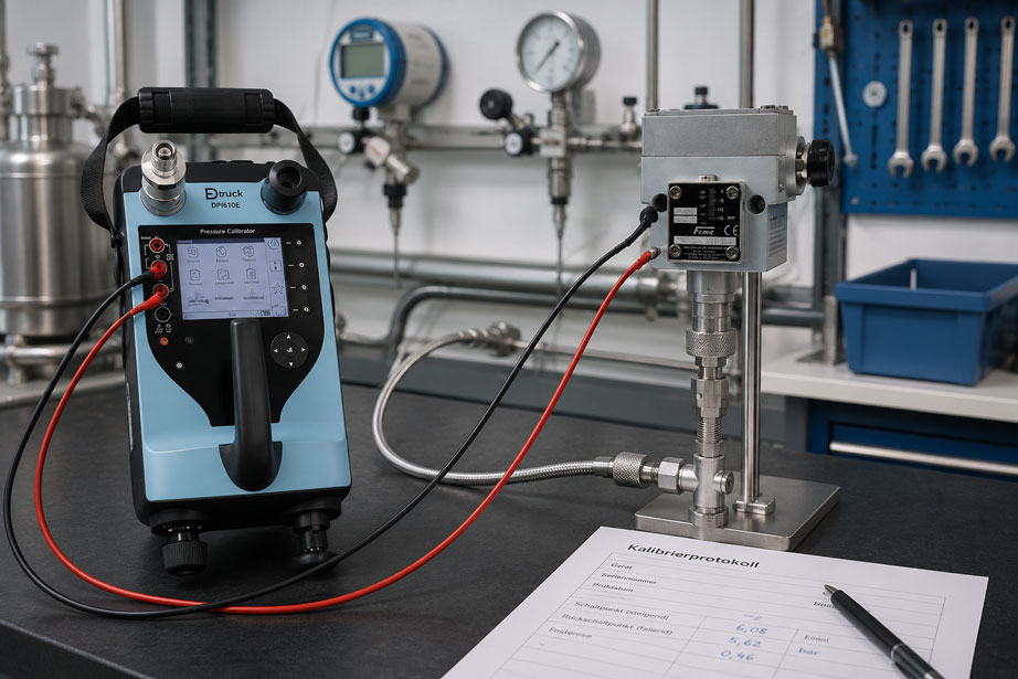
A pressure switch is supposed to switch at 6.0 bar. During the test, the pressure is increased slowly and the contact changes state at 6.08 bar. At first, the test appears to be complete. However, when the pressure is subsequently reduced again, the contact does not reset until 5.62 bar. The difference between the two points is therefore 0.46 bar. This difference is not a measurement error, but the hysteresis or switching differential of the pressure switch.
For a reliable calibration, it is therefore not sufficient to record only a single switching point while the pressure is increasing. A pressure switch has at least two relevant pressure values: the point at which its contact changes state when approaching the switching condition, and the point at which it returns to its original state when the pressure changes in the opposite direction. In addition, it must be checked how reproducible these points are over several cycles.
The direction of the pressure change is particularly important. A high-pressure switch is typically activated as pressure increases and resets when the pressure is subsequently reduced. With a low-pressure switch, the situation may be reversed: it activates as pressure falls and resets when the pressure rises again. The terms switching point and reset point should therefore always be documented together with the corresponding pressure direction.
A complete pressure switch test therefore does not consist of a single pressure value, but of a controlled pressure cycle: record the switching point, reverse the pressure direction, record the reset point, calculate the hysteresis and repeat the procedure several times.
Distinguishing switching point, reset point and hysteresis
A mechanical or electromechanical pressure switch is intentionally designed with a difference between switching and resetting. Without this switching differential, the contact could switch on and off continuously around the threshold in response to small pressure fluctuations. The hysteresis therefore creates a defined separation between the two changes of state.
| Term | Meaning | Example |
|---|---|---|
| Switching point | Pressure at which the contact changes state when approaching the switching condition | Contact switches at 6.08 bar while pressure is increasing |
| Reset point | Pressure at which the contact returns to its original state when the pressure changes in the opposite direction | Contact resets at 5.62 bar while pressure is decreasing |
| Hysteresis / switching differential | Difference between switching point and reset point | |6.08 - 5.62| = 0.46 bar |
| Repeatability | Variation of the switching or reset point over several identical test cycles | Switching point lies, for example, between 6.06 and 6.10 bar |
For hysteresis, the simplified formula ΔpH = |pS - pR| can be used. Here, pS is the determined switching point and pR is the reset point. Using the absolute value is useful because the test direction depends on whether a high-pressure or low-pressure switch is being tested.
Why both pressure directions must be tested
With a typical high-pressure switch, the pressure is initially increased from a lower value. As soon as the contact changes state, the switching point is recorded. The pressure is then held stable slightly above the switching point or increased slightly further to ensure that the new switching state has been clearly reached. The pressure direction is then reversed and the pressure is slowly reduced until the contact resets.
With a low-pressure switch, the test is performed in the opposite way. The starting point is a pressure above the expected switching value. The pressure is reduced in a controlled manner until the switch activates. The pressure is then increased again to determine the reset point. The designation “increasing” or “decreasing” should therefore be included with every documented switching value.
| Switch function | First test direction | Second test direction | Result |
|---|---|---|---|
| High-pressure switch | Increase pressure | Then reduce pressure | Switching point ↑ and reset point ↓ |
| Low-pressure switch | Reduce pressure | Then increase pressure | Switching point ↓ and reset point ↑ |
| Changeover contact | Monitor contact state electrically | Monitor return to original state | Clearly detect both state changes |
A single test run in only one direction would fail to capture an essential part of the switch function. A changed hysteresis in particular may indicate mechanical wear, friction, altered spring forces or problems in the switching mechanism even though the actual switching point is still within the permissible tolerance.
What does a suitable test setup look like?
The test setup requires a controllable pressure source, a sufficiently accurate reference measurement and a method of reliably detecting the electrical contact state. These functions can be implemented using several separate instruments. A portable pressure calibrator with integrated pressure generation and a switch-test function simplifies the setup considerably because the pressure and contact change can be recorded together in time.
- Pressure reference: Measuring range and accuracy must be suitable for the switching point being tested.
- Pressure generation: The pressure must be adjustable very finely and in a controlled manner shortly before the switching point.
- Pressure connection: Hose, adapters and seals must be suitable for the pressure switch and the test medium used.
- Electrical contact measurement: NO, NC or changeover contacts are monitored electrically.
- Leak-tight test circuit: Leaks must not cause such a large pressure change that the actual switching point can no longer be approached reproducibly.
For pneumatic switches, pneumatic testing is often particularly convenient because the pressure can be increased and reduced very finely. At higher pressure ranges or for hydraulic applications, however, a hydraulic setup may be necessary. The process medium is also important: a pressure switch that must not be contaminated with oil should not be connected to a hydraulic calibration circuit without first checking media compatibility.
Detect the switching contact electrically rather than acoustically
During simple tests, the switching point is sometimes determined by listening for the audible “click” of the pressure switch. This method is unsuitable for reproducible calibration. The audible mechanical noise does not necessarily occur at exactly the same time as the electrical change of state of the contact and, on many devices, may hardly be audible at all.
The contact should therefore be detected electrically. A suitable calibrator recognizes whether the contact is open or closed and stores the pressure measured at that moment. Before starting the test, it must be clarified which contact function is present. A normally open contact behaves differently from a normally closed contact; a changeover contact provides both functions.
Older mechanical pressure switches in particular may also exhibit contact bounce. A proper test setup or a switch-test function designed for this purpose prevents a brief electrical state change from being incorrectly interpreted as the final switching point.
Systematically testing a pressure switch
Before the actual test, the device under test and the reference should be allowed to adapt sufficiently to the ambient conditions. The pressure and electrical connections are then made and the test circuit is checked for leaks. The contact state at the initial condition should also be documented.
- Define test data: Determine the nominal switching point, permissible tolerance, switch function and expected hysteresis or reset limit.
- Connect the device under test: Correctly connect the pressure port and electrical contacts to the calibrator.
- Check the initial condition: Ensure that the pressure and contact state correspond to the intended starting point.
- Initially increase pressure quickly to near the expected switching point: This avoids unnecessary test time.
- Reduce the rate of change significantly near the switching point: Then continue changing the pressure monotonically until the contact changes state.
- Record the switching point: Document the pressure value and pressure direction.
- Reverse the pressure direction: Slowly change the pressure in the opposite direction until the contact resets.
- Record reset point and hysteresis: Then repeat the procedure for additional test cycles.
For a reproducible test, the pressure movement in the immediate vicinity of the switching point should be as monotonic as possible. If the pressure is repeatedly moved above and below the presumed switching point, it can no longer be clearly determined from which direction the contact was actually approached.
Why the pressure change must be slow
The rate of pressure change influences the determined switching values. If the pressure is increased very quickly, the actual contact change may occur while the pressure is already continuing to rise. The reference then indicates a higher value than when the switching point is approached slowly. Similar effects can occur during pressure reduction.
This does not mean that the entire test range must be traversed extremely slowly. Instead, it is useful to move relatively quickly to just below the expected switching value and only then reduce the pressure-change rate significantly. In automated test systems, the ramp rate should be defined accordingly and, for recurring tests, used as consistently as possible.
The stability of the pressure source also plays a role. With a mechanical pressure switch having a small hysteresis, pressure pulsations may cause the contact to switch back and forth several times. Before concluding that the switch is faulty, it should therefore be checked whether the fluctuation actually originates from the device under test or from the pressure-generation system.
Multiple switching cycles and repeatability
A single switching cycle basically demonstrates the function of the pressure switch, but provides little information about its repeatability. A mechanical pressure switch may, for example, switch at 6.02 bar during the first cycle, 6.10 bar during the second and 6.05 bar during the third. The average may still be close to the nominal value, while the variation indicates problematic switching behavior.
For this reason, several complete pressure cycles should be performed for quality-relevant tests. The switching point, reset point and hysteresis are recorded separately for each cycle. Particularly with mechanical switches, this makes it possible to determine whether the mechanism operates reproducibly or whether friction, wear or mechanical play is causing varying switching values.
| Test cycle | Switching point ↑ | Reset point ↓ | Hysteresis |
|---|---|---|---|
| 1 | 6.08 bar |
5.62 bar |
0.46 bar |
| 2 | 6.06 bar |
5.61 bar |
0.45 bar |
| 3 | 6.09 bar |
5.63 bar |
0.46 bar |
Such a result gives a very different picture from three switching points that, for example, vary between 5.90 and 6.18 bar. The required number of cycles and permissible variation must be derived from the test specification or the requirements of the application.
Measurement uncertainty in pressure switch calibration
Measurement uncertainty is not determined solely by the specified accuracy of the reference pressure sensor. A pressure switch test captures a dynamic event: the pressure changes and, at a certain point in time, the electrical contact changes state. In addition to the reference measurement, pressure stability, ramp rate, resolution, temperature and repeatability of the device under test may therefore also be relevant.
The reference should be selected so that its uncertainty is sufficiently small compared with the permissible switching-point tolerance. However, even a highly accurate calibrator is of little benefit if the pressure can only be adjusted coarsely shortly before the switching point or if the test circuit is subject to strong pulsations. The quality of pressure generation is therefore practically just as important to the test setup as the reference itself.
The repeatability of the pressure switch should also be distinguished from the measurement uncertainty of the reference system. If the contact itself varies between multiple cycles, this is a property of the device under test and not automatically an uncertainty of the calibrator being used. For a reliable assessment, both contributions should be considered separately.
Distinguishing calibration from adjustment
In technical language, “calibrating” and “adjusting” are often treated as the same thing. From a metrological perspective, however, they are different procedures. During calibration, the actual switching values are determined under defined conditions and compared with the specified values. The pressure switch is initially left unchanged.
If the switch is adjustable and its switching point lies outside the desired specification, an adjustment can then be carried out. The device must subsequently be calibrated or tested again because the adjustment may influence not only the switching point but, depending on the design, also the reset point and therefore the hysteresis.
For clear documentation, it is therefore useful to record the measured values before adjustment separately from the values determined afterwards. Only in this way can it later be traced in what condition the pressure switch was found and how it was subsequently adjusted.
Practical example: pressure switch with a 6 bar setpoint
A mechanical pressure switch is intended to shut down a pump at 6.0 bar as the pressure increases. The device under test is connected pneumatically to a pressure calibrator, while its electrical contact is monitored via the switch-test inputs. The pressure is initially increased to approximately 5.5 bar and then raised much more slowly.
In the first cycle, the contact switches at 6.08 bar. The pressure is then reduced in a controlled manner and the contact resets at 5.62 bar. The hysteresis is therefore 0.46 bar. Two further cycles produce 6.06/5.61 bar and 6.09/5.63 bar. The values are close together and the switching behavior is highly reproducible.
If, on the other hand, only the first switching point of 6.08 bar were documented, two important pieces of information would be lost: the reset point, which is crucial for the actual operating behavior of the pump, and the repeatability of the switch. Only the complete pressure cycle adequately describes the function of the pressure switch.
For practical assessment, the decisive question is therefore not only “At what pressure does the contact switch?”, but also “At what pressure does it reset and how reproducibly does both happen?”
Typical testing errors
Many deviations do not originate in the pressure switch itself, but from an unsuitable test procedure. A pressure change that is too fast, an unstable pressure source or the evaluation of only a single switching event are particularly critical.
- Testing only the switching point with increasing pressure: Reset point and hysteresis remain unknown.
- Changing the pressure too quickly: The switching point is overshot and appears higher or lower than during a controlled test.
- Assessing the contact only by the audible click: Mechanical noise and electrical contact change do not necessarily occur at exactly the same time.
- Performing only one test cycle: Poor repeatability of the switch remains undetected.
- Ignoring leaks in the test circuit: Slowly drifting pressure makes determining the reset point particularly difficult.
- Failing to repeat the complete test after adjustment: An adjustment can change both the switching point and the hysteresis.
- Confusing NO and NC contacts: Before testing, it must be clear which electrical state represents activated and reset.
Which values should be documented?
Good documentation makes it possible to fully reconstruct the pressure switch test later. In addition to manufacturer, type, serial number and measuring-point designation, the calibrator or reference used, the test medium, ambient conditions where required, and the electrical contact state should therefore be documented.
For each test cycle, the switching point, pressure direction, reset point and resulting hysteresis should be recorded. It is also useful to specify whether the values were obtained before or after an adjustment. For recurring tests, this makes it possible to identify whether the switching point, switching differential or repeatability changes over the service life.
Modern documenting pressure calibrators can simplify this work considerably. If contact states are detected automatically and the associated pressure values are stored, the risk of manual transcription errors is reduced, especially during series testing or regular maintenance work.
Pressure calibrator for pressure switch testing
For testing pressure switches, a pressure calibrator that combines pressure generation, precise pressure measurement and electrical contact testing is particularly suitable. One example is the Druck DPI610E. Its integrated switch-test function detects the activation and reset of a pressure switch and calculates the hysteresis from the two pressure values.
Thanks to the integrated pressure generation, the test pressure can be generated directly on the instrument and then reduced again in a controlled manner. This creates a compact test setup suitable both for workshop and calibration tasks and for tests directly on industrial installations. Different versions are available depending on the required pressure range.
Suitable pressure calibrators, reference instruments, pressure pumps and accessories can be found under calibration technology at ICS Schneider. Further information on the solution particularly suitable for this application can be found under Druck DPI610E / DPI610E-IS.
Conclusion
The calibration of a pressure switch should not be reduced to a single switching value. The complete functional cycle is what matters. With a high-pressure switch, the switching point is recorded while pressure is increasing and the reset point while pressure is subsequently decreasing; with a low-pressure switch, the sequence is correspondingly reversed.
The difference between the two points describes the hysteresis or switching differential. It is an essential functional characteristic of the switch and determines, for example, at what pressure a shut-down pump is restarted or an alarm is reset. In addition, multiple test cycles must demonstrate whether the switching values are reproducible.
For reliable results, the test setup requires a suitable pressure reference, finely controllable pressure generation and electrical detection of the contact change. Particularly in the region immediately before the expected switching and reset points, the pressure must be changed slowly and in a controlled manner.
For a complete pressure switch test, the following therefore applies: record the switching point in the intended pressure direction, reverse the pressure direction, determine the reset point, calculate the hysteresis and repeat the complete cycle several times. Only this combination reliably describes the actual switching behavior.
FAQ: Calibrating pressure switches
How do you calibrate a pressure switch?
The pressure switch is connected to a suitable pressure reference and a controllable pressure source. Its electrical contact is also monitored. The pressure is then changed in a controlled manner until the contact switches, after which the pressure direction is reversed and the reset point is recorded.
What is the switching point of a pressure switch?
The switching point is the pressure at which the electrical contact changes state when approaching the intended switching condition. It should always be stated whether the point was determined with increasing or decreasing pressure.
What is the reset point?
The reset point is the pressure at which the contact returns to its original state when the pressure changes in the opposite direction.
How is the hysteresis of a pressure switch calculated?
In simplified form, the hysteresis is the absolute difference between the switching point and reset point: ΔpH = |pS - pR|.
Why must a pressure switch be tested with both increasing and decreasing pressure?
Only then can both the switching point and reset point, and therefore the actual hysteresis, be determined. A test in only one direction does not fully describe the operating behavior of the switch.
Why should the pressure be changed slowly shortly before the switching point?
If the pressure changes too quickly, the switching point can be overshot. The pressure indicated at the moment of contact change may therefore differ from the reproducible switching value obtained when the point is approached slowly.
How many test cycles should be performed on a pressure switch?
This depends on the respective test specification. However, several complete cycles are useful if the repeatability of the pressure switch is to be assessed in addition to the actual switching value.
Is hysteresis in a pressure switch a fault?
Not necessarily. A defined switching differential is intentionally required in many pressure switches so that the contact does not continuously switch back and forth in response to small pressure fluctuations. The decisive factor is whether the hysteresis lies within the limits specified for the application.
Can a pressure switch be adjusted after calibration?
Yes, if the model is adjustable. However, this is an adjustment rather than a calibration. After every adjustment, the complete test cycle should be repeated because not only the switching point but also the reset point and hysteresis may change.
Which calibrator is suitable for pressure switches?
A pressure calibrator with integrated pressure generation and an electrical switch-test function is particularly practical. The Druck DPI610E can detect the switching and reset points of a pressure switch and determine the hysteresis from them.