


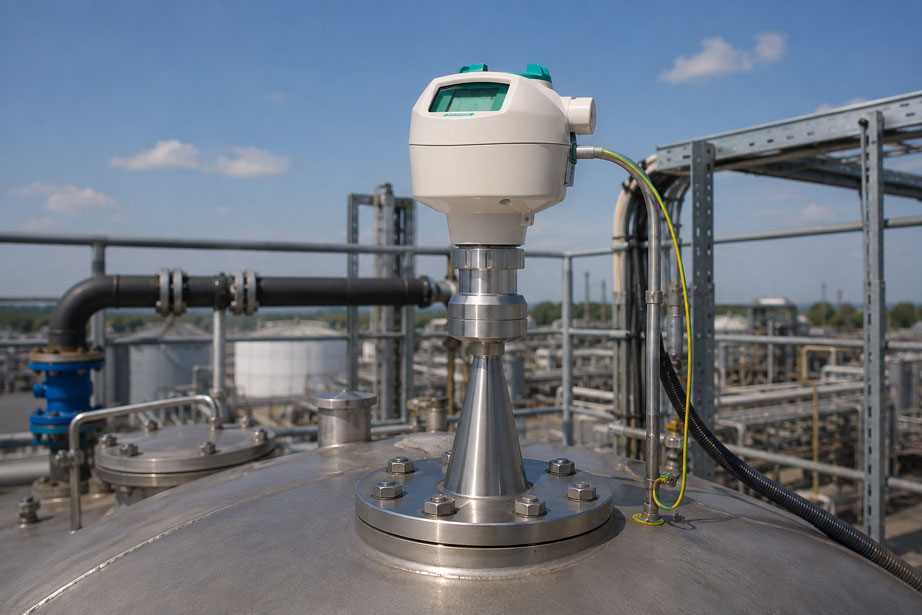
A radar level sensor operates unstably on a vessel with a highly agitated liquid surface. An agitator, inlet flow or foam formation creates changing echoes and the indicated level fluctuates. One possible solution is to perform the radar measurement in a stilling well or stilling tube. Inside this tube, the product surface is often significantly calmer and the radar beam is shielded from internal vessel installations.
However, this does not automatically make the application easier. The stilling well itself becomes an essential part of the radar system. Its internal diameter, the antenna used, transitions, weld seams, side openings and deposits influence the propagation and reflection of the radar signal. An unfavorable geometry can therefore generate false echoes or weaken the actual product echo.
Changes during operation are particularly critical. A clean stainless-steel tube at commissioning may, after several months, become covered with product deposits, corrosion or build-up. At the same time, equalization openings may become blocked. This can change not only the radar behavior but also the actual liquid level inside the stilling well compared with the vessel.
For radar level measurement in a stilling well, it is therefore not sufficient to select only the sensor. The entire tube from the antenna area to the lower end is part of the measuring point and must be considered in terms of geometry, openings, contamination and hydraulic connection to the vessel.
Why use radar in a stilling well at all?
A radar sensor measures the distance between its antenna and the product surface. In an open vessel, the radar signal therefore has to compete with numerous possible reflections. Agitator blades, heating coils, ladders, vessel walls, inlet pipes and other internal installations can generate additional echoes. At the same time, a highly agitated liquid surface can broaden or change the product echo over time.
A stilling well creates a geometrically defined measuring area inside the vessel. The radar beam travels within a metallic tube down to the product surface. The liquid inside the tube is connected to the rest of the vessel through openings or the open lower end of the tube. Ideally, the liquid level inside the tube therefore follows the actual vessel level while waves and turbulence are significantly dampened.
This design can offer major advantages in demanding liquid applications. At the same time, however, the way in which the radar signal propagates changes. The sensor is no longer measuring freely into a large vessel but within a narrow metallic geometry. The tube and antenna must therefore be considered as one system.
How does the stilling well change the radar measurement?
With free-space radar measurement, the electromagnetic signal propagates toward the product surface according to the antenna beam angle. Inside a metallic stilling well, however, the tube wall limits the propagation. The tube therefore influences the electromagnetic conditions of the measurement and, in simplified terms, acts as a guide for the radar signal.
A uniform, smooth and sufficiently large tube geometry can create very stable conditions. Significant changes in internal diameter, protruding weld seams or other metallic obstructions can, on the other hand, generate additional reflections. Openings in the tube wall also interrupt the ideally uniform geometry and must therefore be considered during design and sensor orientation.
| Stilling-well characteristic | Possible influence | Assessment |
|---|---|---|
| Uniform internal diameter | Defined signal propagation | Favorable |
| Smooth inner wall | Fewer additional reflection points | Favorable |
| Diameter step or reduction | Additional echo possible | Avoid where possible |
| Protruding weld seam | Local reflection or false echo | Check internal geometry |
| Side openings | Necessary for level equalization but may affect the echo | Consider during design |
| Deposits | Tube geometry and signal behavior change | Consider maintenance condition |
Why is the pipe diameter important?
The internal diameter of the stilling well must match the radar antenna and radar technology being used. A very narrow tube can influence signal propagation more strongly than a sufficiently dimensioned tube. At the same time, the antenna should not simply be selected as small as possible merely so that it fits mechanically into the tube. Antenna size, signal strength and tube geometry must be evaluated together.
With a radar transmitter using a horn antenna, the antenna should ideally be positioned symmetrically and centrally within the tube. If it is installed significantly off-center or if the edge of the antenna is very close to the tube wall, asymmetrical reflection conditions may occur. Reductions installed directly below the antenna are also particularly problematic.
A larger diameter does not automatically mean a better measurement. What matters is a constant geometry that is suitable for the device. In an existing installation, the actual free internal diameter of the complete stilling well should therefore be considered before selecting the sensor, not merely the flange connection.
Selecting antenna and pipe diameter together
Depending on the device, radar level sensors are available with different antenna designs and sizes. Horn antennas can be particularly suitable for measurements in metallic stilling wells or bypass pipes. The important point is that the antenna must be approved for the application and mechanically compatible with the tube.
For a SITRANS LR250 with horn antenna, Siemens recommends using the largest suitable horn size that fits inside the tube for stilling-well applications. The orientation of the device relative to openings or slots in the stilling well must also be considered. This demonstrates that the mechanical tube design is directly part of the device selection process.
If an existing stilling well is to be reused, its geometry should therefore be recorded first. This includes internal diameter, length, flange, transitions, openings and any internal features. Only then can a suitable antenna or radar configuration be selected.
What is the function of openings and slots?
The stilling well must not become a closed second vessel inside the tank. The liquid level inside the tube must be able to follow the actual vessel level. For this reason, stilling wells are normally hydraulically connected to the vessel, for example through side openings, slots or an open lower end.
These openings must be sufficiently large and distributed in such a way that the liquid level inside the tube can equalize quickly enough. During rapid filling or emptying, an insufficient free cross-section can cause the level inside the stilling well to lag behind the actual vessel level. The radar may then measure correctly inside the tube – but not the current level of the vessel itself.
| Condition | Possible consequence | Typical measurement behavior |
|---|---|---|
| Openings clear and sufficiently dimensioned | Good level equalization | Level follows the vessel |
| Openings partially blocked | Delayed level equalization | Measured value lags during filling or emptying |
| Openings heavily blocked | Stilling well hydraulically isolated | Measured value may differ significantly from vessel level |
| Irregular large openings in radar path | Additional reflections possible | False echoes or unstable echo selection possible |
The openings must therefore satisfy two requirements at the same time: they must provide reliable hydraulic level equalization and maintain a radar-friendly, controlled geometry. Arbitrary perforation of the tube at a later stage is not an optimum solution.
How do deposits affect the measurement?
Deposits are particularly critical in stilling wells because they can cause two different problems. First, they change the internal geometry of the tube and therefore the conditions for radar propagation. Second, they can partially or completely block the equalization openings.
A thin, uniform coating does not necessarily cause an immediate failure. However, if irregular crusts, product build-up or larger deposits form, new reflecting surfaces are created inside the tube. A radar that showed a very clean echo profile during commissioning may therefore suddenly detect additional false echoes after several months.
Deposits around the side openings are particularly problematic. Even if the radar sensor continues to receive a stable echo from the product surface inside the tube, the liquid level there may differ from the actual vessel level. In this case, the problem is not a classic sensor fault but a hydraulic problem in the stilling well.
Avoiding weld seams, transitions and pipe offsets
An ideal stilling well has a free internal diameter that remains as constant as possible over the relevant measuring path. In real installations, however, the tube is often fabricated from several sections. Flanges, welded joints or pipe couplings can therefore introduce geometric changes.
Particularly unfavorable are weld seams protruding into the tube, offsets between two pipe sections and abrupt changes in diameter. Such points can generate additional radar echoes. If one of these echoes lies close to the expected product echo, evaluation can become more difficult, particularly with media that reflect radar weakly.
Existing stilling wells should therefore not only be inspected externally if measurement behavior becomes suspicious. Where possible, the internal condition should also be checked. Especially in older plants, a previously clean tube geometry may have been significantly changed by repair welds, corrosion or product deposits.
Correctly configuring radar in a stilling well
Good mechanical design reduces the amount of configuration work but does not replace it. The radar sensor must be configured according to the actual measuring distance. Empty point, full point or measuring span and, where applicable, further parameters must match the real vessel and stilling-well geometry.
The echo profile is also particularly valuable. It shows which reflections the sensor detects along the measuring path. Fixed echoes at pipe transitions, openings or other structures can therefore be distinguished from a moving product echo. False-echo suppression, however, should not be used to conceal a fundamentally unsuitable tube design.
If false-echo suppression is taught in, the actual level should be known. Otherwise there is a risk that a genuine product echo is accidentally treated as an interfering reflection. After mechanical modifications or intensive cleaning of the stilling well, it should also be checked whether the echo profile has changed significantly.
Systematically diagnosing measurement errors
When problems occur, the first step should be to distinguish whether the radar is detecting the wrong surface or whether the liquid level inside the stilling well actually differs from the vessel level. Both situations can result in an incorrect output signal, but they require completely different corrective measures.
| Observation | Possible cause | Recommended check |
|---|---|---|
| Measured value jumps at certain levels | Fixed echo from an opening, transition or deposit | Check the echo profile over the affected range |
| Measured value responds slowly during filling | Equalization openings partially blocked | Check hydraulic connection of the stilling well |
| Measurement was stable for a long time but becomes increasingly unstable | Deposits or corrosion inside the tube | Inspect the internal condition and antenna area |
| Stable radar value differs from actual tank level | Level in the stilling well does not match the vessel | Check openings and lower tube connection |
| Problem occurs immediately after modification | Changed tube geometry or antenna position | Check diameter, alignment and new reflection points |
A particularly useful diagnostic method is to compare the echo profile and the actual level at the same time. If the product echo remains clear and stable while the indicated level lags behind the tank, a hydraulic problem is more likely. If, on the other hand, the selected echo position jumps between several reflections, the radar side of the installation must be investigated.
Practical example: level starts jumping after extended operation
A radar level transmitter has been measuring the liquid level of a process vessel through a stainless-steel stilling well for several years. During original commissioning, the echo profile was clear. Agitator movement inside the tank had little effect on the measurement and the level indication was stable.
Over time, however, the indication begins to jump occasionally at a certain level. Echo-profile analysis reveals an additional fixed reflection next to the product echo. Inspection of the stilling well shows substantial product build-up around a side opening. The deposit protrudes into the tube cross-section and forms an additional reflecting surface.
After cleaning, the original echo profile is largely restored. At the same time, several other equalization openings are found to be partially blocked. Without cleaning, delayed level equalization between vessel and stilling well could therefore also have developed over time.
This example shows that a changed measured value in a stilling-well radar application does not automatically mean that the radar sensor is defective. The condition of the tube is just as important a part of the measuring point as the electronics themselves.
Correctly planning a stilling-well measuring point
- Check medium and process conditions: Consider temperature, pressure, dielectric constant, tendency to form deposits and corrosiveness.
- Select a radar sensor suitable for stilling-well measurement: Observe antenna design and manufacturer approvals.
- Design pipe diameter and antenna together: Do not select solely on the basis of the available process flange.
- Aim for a constant internal diameter: Avoid abrupt reductions and unnecessary diameter changes.
- Ensure clean internal surfaces: Avoid protruding weld seams and significant pipe offsets.
- Dimension equalization openings hydraulically: Also consider maximum filling and emptying rates.
- Position openings appropriately for radar measurement: Follow device orientation and manufacturer recommendations.
- Provide maintenance access: With media prone to build-up, the tube must be inspectable and cleanable.
- Document the echo profile during commissioning: This provides a reference condition for later diagnostics.
Common mistakes
- Treating the stilling well only as mechanical accessories: The tube directly influences radar propagation and is part of the measuring system.
- Using an arbitrary pipe diameter: Antenna, radar technology and internal geometry must match each other.
- Dimensioning equalization openings too small: The level inside the tube can lag behind the vessel during rapid level changes.
- Ignoring protruding weld seams: Metallic edges inside the tube can generate additional fixed radar reflections.
- Considering deposits only as a radar problem: They can simultaneously impair the hydraulic connection between stilling well and vessel.
- Suppressing every false echo in software: False-echo suppression should not replace poor mechanical design.
- Checking only the antenna: If problems increase over time, the entire internal tube path should also be inspected.
- Equating a stable measured value with the correct vessel level: A radar may correctly measure the level inside the stilling well even though blocked openings mean that this no longer corresponds to the tank level.
Radar level sensor for stilling wells
Radar level measurement in measuring tubes, stilling wells and bypass pipes requires a sensor whose antenna design and signal processing are suitable for this geometry. For industrial liquid applications, one suitable option is the Siemens SITRANS LR250 with stainless-steel horn antenna.
The SITRANS LR250 is a 25 GHz radar level transmitter for continuous liquid and slurry measurement. The horn-antenna version is suitable, among other applications, for stilling wells and bypass pipes. For stilling-well applications, antenna size, tube geometry and orientation relative to existing slots or openings must be considered.
Further radar, hydrostatic, ultrasonic and other level measurement systems can be found under level measurement technology at ICS Schneider. Information on the device specifically relevant to this application can also be found under Siemens SITRANS LR250.
Conclusion
A stilling well can significantly stabilize radar level measurement in turbulent vessels. It shields the measuring path from many internal vessel installations and calms the product surface. At the same time, however, the tube itself becomes a decisive part of the radar measuring point.
The pipe diameter must match the antenna and radar system. An internal geometry that is as uniform as possible reduces additional reflections. Diameter changes, weld seams and other metallic projections can, on the other hand, generate fixed false echoes. The position of the equalization openings should also be considered during the design stage.
Deposits are particularly critical because they can affect both radar behavior and level equalization. A stable radar reading therefore only confirms the liquid level detected inside the stilling well. It does not automatically prove that this level still exactly matches the level in the vessel.
For reliable radar level measurement in a stilling well, the following applies: design the sensor and tube together, maintain a constant free tube cross-section, keep equalization openings functional, and regularly compare the echo profile with the physical condition of the tube.
FAQ: Radar level measurement in a stilling well
Why is a stilling well used for radar level measurement?
A stilling well can calm a highly agitated product surface and shield the radar beam from agitators, ladders, pipes and other internal vessel installations. This can create more stable measuring conditions.
Is every radar level sensor suitable for a stilling well?
No. Antenna design, frequency, pipe diameter and manufacturer approvals must be considered. For such applications, a radar sensor or antenna version explicitly suitable for stilling-well measurement should be selected.
Why is the diameter of the stilling well important?
The metallic tube influences the propagation of the radar signal. An unsuitable or significantly varying internal diameter can generate additional reflections or unfavorable signal propagation conditions.
Why does a stilling well need side openings?
The openings allow the liquid level between the vessel and the stilling well to equalize. Without sufficient hydraulic connection, a different level could develop inside the tube compared with the rest of the vessel.
Can openings in the stilling well interfere with the radar signal?
Yes. Openings interrupt the uniform metallic tube geometry and can generate additional reflections. Their shape, position and the orientation of the radar sensor should therefore be considered during design.
What happens if the stilling-well openings become blocked?
The liquid level inside the tube may only follow the actual vessel level with a delay or may no longer follow it at all. The radar may then technically measure correctly inside the tube while still indicating an incorrect vessel level.
How do deposits inside the stilling well affect measurement?
Deposits can change the free internal diameter and create additional reflecting surfaces. At the same time, they can restrict or block equalization openings. This can cause both radar-related errors and hydraulic level deviations.
Are weld seams inside the stilling well problematic?
External weld seams are normally uncritical for radar measurement. Weld seams protruding into the tube or offsets between tube sections can, however, generate additional radar reflections and should be avoided where possible.
Why should the echo profile be saved or documented during commissioning?
The echo profile of a clean and correctly operating system provides a valuable reference condition. If problems occur later, new reflections caused by deposits or mechanical changes can be identified much more easily.
Which specific radar level sensor is suitable for stilling-well measurement?
For industrial liquid applications, the Siemens SITRANS LR250 with stainless-steel horn antenna is one suitable option. This version is suitable, among other applications, for stilling wells and bypass pipes. The exact antenna and process connection configuration must, however, match the existing tube and process conditions.