


During normal operation, a differential pressure transmitter may measure only 120 mbar differential pressure, while a line pressure of 20 bar is present simultaneously on both process sides. During start-up, however, only one impulse line may initially be opened while the other side of the transmitter is still depressurized. For a short period, almost the full 20 bar then acts on the measuring cell as a one-sided differential pressure.
Three- and five-valve manifolds are intended to make precisely such situations controllable. They form the interface between the process and the differential pressure transmitter and allow both pressure sides to be isolated and equalized in a controlled manner. A five-valve manifold additionally provides valves for controlled venting or draining of the two measuring sides.
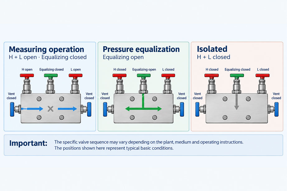
The equalizing valve is particularly important. When it is open, the high-pressure and low-pressure sides are connected on the instrument side. This allows the same pressure to be established on both sides of the measuring cell. In this condition, the differential pressure should ideally approach zero. This state is particularly useful for commissioning, zero-point checks and various maintenance tasks.
A valve manifold is therefore more than just a connection component. The correct valve position determines whether the differential pressure transmitter is measuring, pressure-equalized or isolated from the process. An incorrect sequence, on the other hand, can cause one-sided overload of the measuring cell or uncontrolled release of process medium during venting.
Why does a differential pressure transmitter need a valve manifold?
A differential pressure transmitter has two process sides. The high-pressure side is often designated H, HP, + or p1, while the low-pressure side is designated L, LP, - or p2. The measured value is calculated in simplified form as:
Δp = pH - pL
During normal operation, both process pressures should act simultaneously on their respective measuring chambers. For maintenance, commissioning and zero-point checks, however, this connection must be altered in a controlled manner. If the two impulse lines were connected directly to the transmitter, many tasks would require the process measuring point to be disconnected with considerably more effort.
A valve manifold therefore combines several functions in one compact component. The process sides can be isolated, the two instrument sides can be connected to each other and, with a five-valve manifold, individual sides can additionally be vented or drained in a controlled manner.
How does a 3-valve manifold work?
A conventional 3-valve manifold has three valves: one isolation valve for the high-pressure side, one isolation valve for the low-pressure side and one equalizing valve between the two instrument sides.
| Valve | Function | Typical position during measurement |
|---|---|---|
| H/HP isolation valve | Connects the high-pressure process side to the transmitter | Open |
| L/LP isolation valve | Connects the low-pressure process side to the transmitter | Open |
| Equalizing valve | Connects the two instrument sides to each other | Closed |
During normal measurement, the H and L sides must transmit the actual process pressures separately to the measuring cell. The equalizing valve therefore remains closed. If it were fully opened during measurement, both instrument sides would be connected and the differential pressure would largely collapse.
What additional functions does a 5-valve manifold provide?
The WIKA IV50 and IV51 five-valve manifolds offered by ICS have two additional vent valves compared with the three-valve versions. This allows each pressure side to be vented or depressurized individually.
This is particularly useful during commissioning, flushing, maintenance and testing. In liquid applications, for example, unwanted gas bubbles can be removed. In gas applications, accumulated condensate may be relevant depending on the installation. Testing the transmitter while installed is also made easier by the additional valve functions.
| Function | 3-valve manifold | 5-valve manifold |
|---|---|---|
| Isolate H side | Yes | Yes |
| Isolate L side | Yes | Yes |
| Equalize pressure between H and L | Yes | Yes |
| Vent/drain H side individually | No, or external solution required | Yes |
| Vent/drain L side individually | No, or external solution required | Yes |
The suitable valve manifold therefore depends not only on the transmitter. Medium, pressure, required maintenance work, desired testing options and the complete hook-up must all be taken into account.
What does the equalizing valve do?
The equalizing valve connects the two pressure chambers on the instrument side. If the process conditions and the positions of the other valves are suitable, the same pressure is established at both transmitter connections.
The resulting differential pressure is then ideally:
Δp ≈ 0
This function has two important purposes. First, during start-up it can help prevent one side of the measuring cell from already being exposed to full line pressure while the other side is still depressurized. Second, it allows the zero point to be checked under a common static pressure.
The equalizing valve must therefore not be confused with a vent valve. During equalization, the pressure is not automatically released to the atmosphere. Instead, the H and L sides are connected together on the instrument side.
Which valves are open during normal measurement operation?
During normal differential pressure measurement, both process sides must be connected to the transmitter and the internal equalization must be closed.
The typical basic position is therefore:
- H/HP isolation valve: open,
- L/LP isolation valve: open,
- Equalizing valve: closed,
- Vent valves of a 5-valve manifold: closed.
Only in this configuration can the actual process differential pressure build up between the two measuring chambers. However, the specific valve labeling and arrangement must always be checked against the documentation for the particular valve manifold and transmitter.
How is a differential pressure measuring point started up in a controlled manner?
During start-up, the main objective is to avoid a high one-sided differential pressure acting on the measuring cell. The transmitter is therefore initially brought into a pressure-equalized condition. Both process sides are then connected in a controlled manner. Only when both sides are at the intended process conditions is the equalizing valve closed and the actual differential pressure measurement enabled.
The basic principle is therefore:
- Establish pressure equalization between the two instrument sides.
- Apply process pressure to the measuring arrangement in a controlled manner.
- Connect both process sides according to the specified valve sequence.
- Check that both sides are correctly pressurized and that the impulse lines are properly filled or vented.
- Close the equalizing valve.
- Check the measured value for plausibility.
The exact sequence in which the H and L isolation valves are opened cannot be defined identically for every measuring point. Equipment manufacturers, transmitter manufacturers and individual measurement tasks may specify different procedures. The key principle is protection: the measuring cell must not be exposed to an impermissible one-sided load during switching.
How is the measuring point taken out of service?
When shutting down the measuring point, controlled pressure equalization should also be established before unfavorable one-sided pressure conditions can occur. The basic principle is therefore the reverse of commissioning: the differential pressure at the measuring cell is first reduced or equalized in a controlled manner, after which the process sides are isolated.
During maintenance, it must also be clarified whether static process pressure remains trapped in the valve manifold, transmitter or impulse lines. Closed process valves do not automatically mean that the cavities on the instrument side are depressurized.
A transmitter or fitting may only be opened after the trapped pressure has been safely and intentionally released. With hazardous, toxic, hot or environmentally critical media, a vent connection must not simply be opened uncontrolled to the surroundings. The medium must be safely collected, returned or discharged in accordance with the plant design.
Checking the zero point under line pressure
A major advantage of a valve manifold is the ability to check the zero point of the differential pressure transmitter under a common static process pressure. For this purpose, a defined condition is established in which both sides of the measuring cell see the same pressure.
If the transmitter still shows, for example, +12 mbar in this condition, it must be checked whether complete pressure equalization has actually been achieved. Possible causes include an equalizing valve that is not fully open, trapped gas bubbles, liquid columns, blocked impulse lines or an actual zero-point shift of the transmitter.
Such a check is more meaningful than immediately adjusting the zero point. It should always first be ruled out that the installation itself is generating a real pressure difference.
Venting and draining with a 5-valve manifold
The two additional valves of a 5-valve manifold provide controlled access to the individual pressure sides. Depending on the medium and installation, they can be used for venting, draining, flushing or testing.
In liquid measurements, gas bubbles in an impulse line are problematic because they are compressible and can change the dynamic behavior. Different liquid columns can additionally generate a hydrostatic differential pressure. In gas measurements, on the other hand, unwanted liquid accumulation or condensate may be critical.
Vent valves may only be opened if the resulting pressure and media flow are clearly understood. Particularly at high line pressure, it must be clarified before opening whether the relevant side has been safely isolated from the process and where the escaping medium will be routed.
Influence of impulse lines and filling condition
A perfectly operated valve manifold cannot compensate for installation errors in the impulse lines. Both lines are part of the differential pressure measuring system. Different filling conditions, blocked lines or different elevations can generate a real additional differential pressure.
Especially with very small differential pressure measuring ranges, even a small difference in the height of a liquid column can produce a clearly visible measured value. An apparently incorrect zero point may therefore actually originate from the installation.
During commissioning and maintenance, not only the valve positions should therefore be documented. Routing, filling condition, venting or draining and the temperature of the impulse lines should also be checked.
Why is one-sided overload critical?
A differential pressure transmitter may be designed for a high static line pressure while at the same time having a very small differential pressure measuring range. These two specifications must not be confused.
For example, both sides of a transmitter may be exposed to approximately 20 bar during normal operation, while the differential pressure is only 100 mbar. As long as both sides are exposed to approximately 20 bar, the measuring cell sees only the small differential pressure.
If, however, one side is fully pressurized to 20 bar while the opposite side remains depressurized, the temporarily applied differential pressure is approximately:
20 bar - 0 bar = 20 bar
This is two hundred times greater than a measuring range of 100 mbar. Whether the measuring cell can withstand this condition without damage depends on its specified one-sided overload capability. This is exactly why the valve sequence has a mechanical protection function and is not merely a matter of operating convenience.
Practical example: 20 bar line pressure and 100 mbar measuring range
A differential pressure transmitter monitors the pressure drop across a process filter. The normal line pressure is approximately 20 bar, while the expected differential pressure is only between 20 and 100 mbar.
After maintenance, both process isolation valves are closed. If the operator were simply to fully open one side while leaving the other side closed initially, almost the full line pressure could temporarily act on the measuring cell from one side.
Instead, in accordance with the defined procedure for the measuring point, pressure equalization is established first. The process sides are then connected in such a way that both measuring chambers are brought to the common line-pressure level in a controlled manner. Only then is the equalizing valve closed.
The actual differential pressure across the filter is now established again. If the transmitter shows, for example, 65 mbar, this value results from the difference between the two process sides and not from one-sided pressurization during start-up.
This example shows why the small measuring span of a differential pressure transmitter must never be confused with the high common line pressure. The valve manifold ensures that both quantities remain controlled and separated during commissioning and maintenance.
Systematic procedure
- Clearly identify the valve manifold: Check whether it is a 3- or 5-valve design, the H/L assignment and the function of each valve using the documentation.
- Know the maximum line pressure, differential pressure measuring range and permissible one-sided overload of the transmitter.
- Before commissioning, check impulse lines, fittings and filling condition.
- Initially bring the transmitter into a safe pressure-equalized condition.
- Connect both process sides according to the sequence specified for the particular measuring point.
- Only then close the equalizing valve and enable differential pressure measurement.
- For zero-point checks, establish a clearly defined pressure equalization condition and do not immediately readjust the transmitter.
- Before maintenance work, isolate the process sides and release trapped pressure in a controlled manner.
- Safely collect or discharge vented and drained media.
- Document valve positions and the intended operating sequence for recurring maintenance work.
Common mistakes
- Fully pressurizing one process side first: This can cause a high one-sided load on the measuring cell.
- Leaving the equalizing valve open during measurement: The actual differential pressure is reduced or largely equalized.
- Confusing the equalizing valve with a vent valve: Equalization connects the two instrument sides; it does not automatically depressurize them.
- Assuming closed process valves mean a depressurized transmitter: High pressure may still be trapped between the valve and measuring cell.
- Opening a vent valve uncontrolled under full process pressure: Process medium can escape with high energy.
- Using one universal H/L valve sequence for every application: The specific operating instructions and plant function are decisive.
- Correcting the zero point immediately: First ensure that both measuring sides actually see the same pressure.
- Ignoring the impulse lines: Gas bubbles, condensate, liquid columns and blockages can cause measurement errors despite correct valve positioning.
- Guessing valve functions based on their physical position: High-pressure, low-pressure, equalizing and vent valves must be identified from the actual markings or documentation.
WIKA DPT-20 and IV30/IV31/IV50/IV51
One specific differential pressure transmitter for industrial process applications is the WIKA DPT-20. The device is suitable, among other things, for filter and pump monitoring, flow measurement using differential pressure elements and level measurements. Available measuring ranges extend from very small differential pressures to several bar, while a high common static process pressure is possible depending on the version.
Suitable valve manifolds can be used for safe process connection. The WIKA IV30 and IV31 are designed as 3-valve manifolds with two isolation valves and one equalizing valve. The equalizing valve connects the positive and negative sides and therefore enables controlled pressure equalization, particularly during commissioning and zero-point checks.
The WIKA IV50 and IV51 additionally feature two vent valves. This allows each pressure side to be vented individually or made accessible for corresponding service and test work.
WIKA offers standardized center distances of 37 and 54 mm, allowing the valve manifolds to be combined with WIKA differential pressure instruments and common process transmitters. Fully assembled and leak-tested hook-up solutions are also available.
Suitable devices can be found under pressure measurement technology at ICS Schneider. Further information is available for the WIKA DPT-20 differential pressure transmitter and the WIKA IV30, IV31, IV50 and IV51 valve manifolds.
Conclusion
Three- and five-valve manifolds are a central component of an industrial differential pressure measuring point. They not only allow isolation from the process, but above all enable controlled pressure equalization between both sides of the measuring cell.
During normal measurement operation, both process isolation valves are open and the equalizing valve is closed. For commissioning, zero-point checks and shutdown, a pressure-equalized condition is deliberately established instead.
A five-valve manifold extends these functions with separate venting or draining options. This allows individual pressure sides to be checked, vented or depressurized in a controlled manner. However, this function must be used appropriately according to the medium, process pressure and safety concept.
It is particularly important to distinguish between differential pressure and common line pressure. A transmitter may measure only a few millibar while both sides are simultaneously exposed to a static pressure of many bar. An incorrect valve sequence can temporarily apply this high line pressure to the measuring cell as a one-sided differential pressure.
For reliable operation, the following therefore applies: clearly identify the valve functions, first establish a safe pressure condition, connect or isolate the H and L sides in a controlled manner and only close or open the equalizing valve when the process conditions allow it. The specific valve sequence must always match the individual measuring point and the manufacturer’s documentation.
FAQ: Three- and five-valve manifolds on differential pressure transmitters
What is a 3-valve manifold used for?
A 3-valve manifold has two isolation valves for the high- and low-pressure sides and one equalizing valve. This allows the differential pressure transmitter to be isolated from the process and pressure equalization to be established between the two measuring sides.
What is the difference between a 3-valve and a 5-valve manifold?
In addition to the two isolation valves and the equalizing valve, a 5-valve manifold has two vent or drain valves. This allows the two pressure sides to be vented or depressurized more selectively for service work.
What are the valve positions during normal measurement operation?
In principle, the isolation valves on the high- and low-pressure sides are open and the equalizing valve is closed. On a 5-valve manifold, the vent valves are also closed during normal measurement operation.
What happens when the equalizing valve is opened?
The high- and low-pressure sides are connected on the instrument side. As a result, the differential pressure at the measuring cell approaches zero, provided no other hydraulic or pneumatic effects generate a pressure difference.
Why is the equalizing valve used during commissioning?
It helps bring both sides of the measuring cell to a comparable pressure level in a controlled manner and therefore helps avoid unfavorable one-sided overload during start-up.
Can the transmitter be depressurized using the equalizing valve?
Not automatically. The equalizing valve connects the two measuring sides. It does not necessarily release the trapped pressure to atmosphere or to a drain system.
Can the transmitter zero point be checked using a valve manifold?
Yes. If a defined condition with the same pressure on both measuring sides is established, the differential pressure should ideally approach zero. This allows the zero point to be assessed even under a common static line pressure.
Why is an incorrect isolation sequence dangerous?
If one side of the differential pressure transmitter is already exposed to high line pressure while the other side is still depressurized, almost the full line pressure can act on the measuring cell as a one-sided differential pressure.
Is there a universal sequence for the H and L valves?
No. The protection principle is general, but the specific sequence may depend on the transmitter, valve manifold, process and plant concept. The operating instructions for the particular measuring point are therefore decisive.
What are the additional valves on a 5-valve manifold used for?
They allow the individual measuring sides to be vented or depressurized in a controlled manner and can be used for commissioning, maintenance, flushing and certain test tasks.
Which specific valve manifold is suitable for a differential pressure transmitter?
Examples include the WIKA IV30 and IV31 as 3-valve manifolds and the IV50 and IV51 as 5-valve manifolds. They are designed for differential pressure instruments and common process transmitters.
Which differential pressure transmitter is suitable for use with them?
One specific example is the WIKA DPT-20. It is suitable, among other applications, for filter monitoring, flow measurement, level measurement and other industrial differential pressure measurements and can be combined with suitable 3- or 5-valve manifolds.