


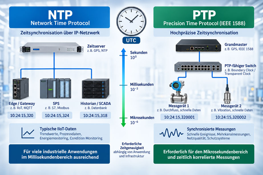
A pressure value receives the timestamp 10:24:15.320. A few milliseconds later, another data point reports a pump shutdown. At the same time, a vibration sensor records an unusual peak. In the historian, it appears as though the sequence of events can be determined unambiguously.
Whether this conclusion is actually reliable, however, depends on how accurately the clocks of the participating devices are synchronized with one another.
A timestamp with three, six or even nine decimal places does not mean that the underlying clock is running with corresponding accuracy. A system can generate timestamps with microsecond resolution and still be several milliseconds offset from another device.
This is where the decision between NTP and PTP begins.
NTP – the Network Time Protocol – is designed to synchronize computers and devices over IP networks and is entirely sufficient for many industrial measurement-data applications. Historian data, energy consumption, slowly changing process values, maintenance information or typical condition-monitoring trends often do not require synchronization in the microsecond range.
PTP – the Precision Time Protocol according to IEEE 1588 – becomes relevant when measurements from several spatially distributed devices must be correlated very precisely in time. Typical examples include fast event analysis, simultaneous multi-channel measurements, power-quality measurements or applications in which even a time offset of a few hundred microseconds can lead to incorrect interpretation.
The question should therefore not be: “Which protocol is more accurate?”
The more important question is: How large may the time error between two measured values be before the later technical interpretation becomes incorrect?
Only from this requirement can it be determined whether a properly configured NTP system is sufficient or whether a PTP infrastructure with hardware timestamping and suitably supporting network components is required.
The key point is: The highest technically achievable time accuracy is not automatically the correct solution. NTP or PTP should be selected according to the permissible time error of the measurement task. Sampling rate, timestamp location, network, hardware timestamping and synchronization status must all be considered together.
Table of Contents
- Why must industrial measurement data be synchronized?
- How accurate does the time actually need to be?
- How does NTP work?
- How does PTP work?
- Direct comparison of NTP and PTP
- When is NTP sufficient for industrial measurement data?
- When does PTP become useful or necessary?
- Why hardware timestamping is crucial for PTP
- What role do switches and network architecture play?
- Correctly understanding Grandmaster, Boundary Clock and Transparent Clock
- Do not confuse time synchronization with timestamp location
- Do not confuse sampling rate with time accuracy
- Why synchronized clocks do not eliminate sequential polling
- Correctly handling UTC, time zones and daylight saving time
- What happens during buffering and network interruptions?
- Monitor synchronization quality together with measurement data
- Correctly plan time sources and redundancy
- Consider time synchronization as part of IT/OT security
- NTP or PTP: practical selection guide
- Systematically diagnose typical faults
- IIoT solutions from ICS Schneider
- Conclusion
- Frequently asked questions about NTP and PTP
1. Why must industrial measurement data be synchronized?
For a single measuring point, a small deviation in its internal clock often has little significance. The situation becomes critical as soon as data from different devices are compared.
A machine can, for example, simultaneously record pressure, flow, current consumption, vibration and valve states. During a later fault analysis, it may be necessary to determine which event occurred first.
If all devices have different clock times, the database may display an apparently precise event sequence, even though this sequence does not necessarily correspond to reality.
A pressure drop may, for example, appear in the historian ten milliseconds before a valve switching event, even though the valve actually switched first. Such an error is not caused by inaccurate pressure measurement, but by an incorrect time reference.
Time synchronization therefore ensures that different devices relate their timestamps to a common time base.
The faster the process being investigated, the smaller the permissible time offset between the participating measuring points generally needs to be.
For a tank level that changes over several minutes, ten milliseconds are irrelevant. For two highly dynamic current or vibration signals, the same ten milliseconds may already produce an incorrect event sequence.
2. How accurate does the time actually need to be?
The selection of the time-synchronization method should therefore begin with a technical requirement.
It must be defined what maximum time error between two data sources is still acceptable.
A practical approach is to first consider the fastest relevant process change. If a process is evaluated only every ten seconds, a synchronization requirement of one microsecond will normally provide no additional benefit.
If, by contrast, events are being compared that may occur only a few milliseconds apart, the time error must be significantly smaller than this interval.
| Application | Typical timing requirement | Technical approach |
|---|---|---|
| Slow trend data, level, temperature, energy | Tenths of a second to seconds often sufficient | NTP generally sufficient |
| Historian, batch records, normal process alarms | Milliseconds to several tens of milliseconds depending on application | Local NTP usually sufficient; verify actual deviation |
| Machine events and rapid root-cause analysis | A few milliseconds or better | Validate NTP; consider PTP for stricter requirements |
| Synchronized multi-channel measurements | Below one millisecond | PTP with suitable hardware often useful |
| Highly precise time-correlated measurements | Microsecond range or better | PTP with hardware timestamping and a PTP-capable network |
These ranges are not fixed protocol limits. They serve as planning guidelines.
A high-quality NTP system in a local network can perform significantly better than an unfavorable NTP connection across several unknown networks. Conversely, a poorly designed PTP system does not automatically achieve microsecond accuracy.
The required accuracy must therefore be verified in the actual system.
3. How does NTP work?
NTP synchronizes the clock of a client with one or more time sources over an IP network.
The client exchanges time information with the time server and uses this information to estimate both the clock offset and the transmission delay.
An NTP infrastructure can be structured hierarchically. A central time server can, for example, use a high-quality external reference and distribute its time to PLCs, edge gateways, servers and other network devices.
NTP does not simply attempt to force the client clock to a new value at regular intervals. Suitable implementations can continuously discipline the local clock and correct small deviations in a controlled manner.
However, the achievable accuracy does not depend on the protocol alone.
Network latency, different forward and return paths, operating system, software, local oscillator and system load all influence the achievable synchronization.
Asymmetric network paths are particularly problematic. If a time packet takes significantly longer in one direction than in the other, the clock offset calculated from the transmission can contain a systematic error.
For conventional IT, SCADA, historian and many IIoT applications, NTP is nevertheless very well suited because the required accuracy is often in the millisecond range or above.
4. How does PTP work?
PTP stands for Precision Time Protocol and is defined in the IEEE 1588 standard.
The protocol was developed for distributed network devices that must be synchronized significantly more precisely than typical computers in a conventional IT network.
In a PTP system, there is a primary clock that acts as the Grandmaster. Other devices synchronize their local clocks to this reference.
PTP exchanges special synchronization and delay information across the network for this purpose.
The key difference compared with a typical NTP setup is not only the protocol itself. For high accuracy, PTP can generate timestamps very close to the actual transmission or reception point of an Ethernet frame.
This greatly reduces the influence of delays caused by the operating system, software stack and queues.
With suitable hardware and an appropriately designed network infrastructure, synchronization in the sub-microsecond range can be achieved.
PTP is therefore particularly useful when multiple devices genuinely need to measure at the same time rather than merely display approximately the same clock time.
5. Direct comparison of NTP and PTP
| Characteristic | NTP | PTP |
|---|---|---|
| Typical focus | General clock synchronization in IP networks | Precise synchronization of distributed measurement and automation devices |
| Typical accuracy in industrial practice | Usually millisecond range, depending on network and implementation | Microsecond or sub-microsecond range with suitable infrastructure |
| Hardware timestamping | Not required for typical applications | Particularly important for high accuracy |
| Switch requirements | Standard Ethernet infrastructure is often sufficient | PTP-capable switches may be required for high accuracy |
| Central reference | NTP time server | PTP Grandmaster |
| Typical application | Servers, gateways, SCADA, historian, normal process data | Synchronized measurement systems, fast events, highly precise data acquisition |
| Planning effort | Comparatively low | Higher; profiles, hardware, switches and topology must be compatible |
The table also shows why the blanket statement “PTP is better” is technically of little value.
A PTP system requires more planning and often specially supported hardware. If an application only requires a time accuracy of, for example, several tens of milliseconds, there is no measurement-related advantage.
Conversely, NTP should not be used simply out of habit if an application actually requires synchronized measurements in the microsecond range.
6. When is NTP sufficient for industrial measurement data?
NTP is entirely sufficient for a large proportion of industrial IIoT data.
A temperature sensor that provides a new value every ten seconds normally does not require a clock synchronized to microseconds.
The same applies to many data sets from energy monitoring, tank monitoring, compressed-air consumption, long-term trends, maintenance or production KPIs.
Conventional historian data with sampling intervals of one second or several seconds can also be operated reliably in many cases using a properly designed local NTP infrastructure.
The important point is that an arbitrary public time server reached through an uncontrolled Internet connection should not be used as the sole reference.
For industrial systems, a controlled internal time architecture is preferable. Defined NTP servers are provided and the relevant OT systems synchronize through known network paths.
The actual synchronization deviation should also be monitored.
NTP is therefore not sufficient merely because an application is described as “IIoT”. It is sufficient when its real synchronization quality is significantly better than the time deviation permitted for the measurement task.
7. When does PTP become useful or necessary?
PTP becomes relevant as soon as the time reference itself forms part of the measurement quality.
One example is a spatially distributed multi-channel measurement. Two measuring instruments are intended to capture the same fast event and their signals are later to be overlaid.
With a time offset of five milliseconds, the curves may already be visibly shifted relative to one another.
Another example is the sequence of fast protection or switching events. If several devices record events within very short intervals, their common time base must be significantly more accurate than the time spacing between the events to be distinguished.
Electrical network and power measurements can also have much stricter requirements because phase and time progression are direct parts of the measurement information.
PTP can provide a common high-precision time base for several devices in such applications.
However, an important point remains: PTP synchronizes clocks. It does not replace a suitable measurement system and does not automatically guarantee that two sensors actually sample at exactly the same instant.
Internal measurement cycles, triggering and signal processing must also be synchronized or clearly defined.
8. Why hardware timestamping is crucial for PTP
One of the most important sources of time uncertainty in a conventional computer is the software path between the network and the application.
A received Ethernet packet passes through the network interface, driver, operating system, queues and application.
The time required for this is not constant.
If a timestamp is generated only in the application, it therefore also contains variable software-related delays.
With hardware timestamping, the relevant timestamp is instead generated directly in the network hardware or very close to the actual transmission or reception time.
This characteristic is crucial for high-precision PTP applications.
A device that merely “supports PTP” in software is therefore not automatically equivalent to a device whose network interface supports full hardware timestamping.
When selecting devices, it must be checked which timestamping method is actually used and what synchronization accuracy is specified for the specific configuration.
9. What role do switches and network architecture play?
Several Ethernet switches are often located between the Grandmaster and the measuring instrument.
Each switch processes and buffers data packets. The resulting delay is not constant under all operating conditions.
In a conventional data network, this variation is usually unproblematic. For time distribution in the microsecond range, however, it can become relevant.
PTP-capable network components can account for network-induced delays much more accurately.
This means that PTP must not be considered merely as a feature of the end device.
Grandmaster, switches, VLAN concept, network path, timestamping hardware, PTP profile and end devices together form the synchronization chain.
A permanently different propagation time in the forward and return directions can also produce a systematic time error.
Precise PTP planning should therefore use network paths that are as symmetrical or as well characterized as possible and subsequently verify the actual synchronization quality.
10. Correctly understanding Grandmaster, Boundary Clock and Transparent Clock
In small PTP networks, a Grandmaster can directly synchronize multiple end devices.
In larger networks, additional PTP-capable network components are used.
A Boundary Clock has its own synchronized clock. It receives PTP on one side and then provides its own PTP time reference for a downstream network segment.
This divides a large network into several time-controlled segments.
A Transparent Clock operates differently. It accounts for the time that PTP messages spend inside the switch and provides this information for further correction.
Both concepts reduce the influence of network components on time transfer.
Which method is used depends on the PTP profile and network architecture.
The statement “switch supports PTP” is therefore not sufficient for planning. The supported profile, clock type, delay mechanism and actual hardware functionality are relevant.
11. Do not confuse time synchronization with timestamp location
Even the best synchronized clock is useful only if the timestamp is generated at the correct point.
A sensor may, for example, acquire a measured value at 10:00:00.100.
The value then takes 50 ms to reach the PLC, another 100 ms to reach the edge gateway and several seconds to reach the cloud.
If the timestamp is generated only when the value arrives in the cloud, it says nothing about the original measurement time.
NTP or PTP synchronizes the participating clocks but does not automatically determine which of these times is stored.
For time-critical measurement data, the relevant timestamp should therefore be generated as close as possible to the actual data acquisition.
If a sensor cannot generate its own timestamp, the PLC or edge gateway can, for example, generate one when the value is actually read.
However, it must then be clearly documented whether this is a measurement time, polling time, gateway reception time or server time.
This point is often more important than the decision between two synchronization protocols.
12. Do not confuse sampling rate with time accuracy
A sampling rate of 1 kHz means that a system theoretically captures one measured value every 1 ms.
It does not automatically mean that the clock of this system is synchronized to within 1 ms of a second device.
Conversely, a device can be synchronized to within a few microseconds while still generating only one new measured value per second.
Three characteristics must therefore be considered separately:
Sampling rate → timestamp resolution → synchronization accuracy.
For a time-correlated multi-channel measurement, all three characteristics must be suitable for the application.
A timestamp with six decimal places after the second therefore does not prove microsecond accuracy.
13. Why synchronized clocks do not eliminate sequential polling
In brownfield plants, measuring instruments are often integrated via Modbus RTU or other cyclically polled interfaces.
A gateway may then query several sensors one after another.
Even if the gateway is perfectly synchronized to a time reference, the individual values are not generated at the same time.
Sensor 1 may be read at the beginning of a polling cycle while sensor 20 is read significantly later.
If all measured values are subsequently assigned the same gateway timestamp, an apparent simultaneity is created that did not physically exist.
A more accurate clock does not solve this problem.
For fast event analysis, it must additionally be known when each measurement actually took place.
Devices with their own timestamped data acquisition are therefore significantly better suited to this purpose than systems in which a gateway only reads current register values one after another.
14. Correctly handling UTC, time zones and daylight saving time
Industrial measurement data should use an unambiguous time base for storage and system-wide exchange wherever possible.
UTC is well suited for this because timestamps remain independent of local time zones and daylight saving time.
Conversion to local time then takes place only during display or reporting.
If local time is stored directly instead, switching between summer and winter time can create duplicated or apparently missing time ranges.
For event data, it should therefore also be clearly defined which time scale and UTC reference are being used.
With PTP, the time base of the selected profile or system must likewise be configured correctly.
A highly precise synchronized clock with an incorrectly interpreted UTC reference will still generate incorrect absolute timestamps.
15. What happens during buffering and network interruptions?
An IIoT connection can temporarily fail while sensors and the machine continue to operate.
An edge gateway can then buffer measurement data locally and transmit it later.
For the time information, it is crucial that the original measurement time is retained.
If buffered values are assigned a new current timestamp only when they are later transmitted, the actual time history is lost.
The synchronization itself can also fail during a communication interruption.
The local clock then continues running on its own oscillator and begins to drift relative to the reference.
How quickly this deviation grows depends on the quality of the local clock and the environmental conditions.
Following a loss of synchronization, a seemingly perfect timestamp should therefore not simply continue to be stored without additional context. The synchronization status or time quality should also remain traceable.
16. Monitor synchronization quality together with measurement data
For high-quality industrial data, it is not sufficient to check only once during commissioning whether the clock is correct.
Time synchronization itself should be monitored.
Depending on the system, parameters such as the current offset from the reference, synchronization status, time source used, last successful synchronization and any change of time source can be logged.
With PTP, it may additionally be relevant which Grandmaster is currently being used.
If synchronization is lost, this should be visible in the monitoring system.
For particularly time-critical data, it may be useful to mark measured values from periods with uncertain time references with a corresponding quality status.
This prevents a historian from comparing two timestamps years later as though they were accurate to the microsecond even though one of the devices was not synchronized at the time.
17. Correctly plan time sources and redundancy
The central time source can also fail.
For this reason, multiple controlled time servers are often configured for NTP.
A PTP system can likewise provide redundant time sources or Grandmasters.
However, redundancy does not mean simply entering as many different time sources as possible.
The sources themselves should be traceable to a consistent reference and their status must be monitored.
When switching between two time sources that do not agree, the local system time may otherwise jump.
Such a time jump can lead to duplicated timestamps, apparently backward-running time or an incorrect event sequence in measurement data.
For critical systems, behavior during switchover and holdover should therefore also be considered.
18. Consider time synchronization as part of IT/OT security
In modern industrial systems, the time base is not relevant only for measurement technology.
Logs, audit trails, user logins, certificates, security events and fault records also use timestamps.
An incorrect clock can therefore make the subsequent analysis of an IT or OT security event significantly more difficult.
Time servers should therefore be protected and controlled as part of the infrastructure.
OT devices should preferably use defined internal time sources and should not be allowed to access arbitrary external servers without planning.
With PTP, it must also be considered that an incorrect or maliciously selected Grandmaster can affect the time base of many devices at once.
Network segmentation, controlled communication paths, device monitoring and logged configuration changes therefore also belong in the time-synchronization concept.
19. NTP or PTP: practical selection guide
The maximum permissible time error should be defined first.
If measurement data is used only for long-term trends, consumption analysis, maintenance or normal process visualization, a properly designed NTP infrastructure is the more sensible solution in most cases.
If fast events from different devices are to be correlated, the actual achievable NTP deviation should first be measured and compared with the requirement.
If the required synchronization is already below one millisecond or in the microsecond range, PTP with suitable hardware and network support should be planned.
It must then be verified that all relevant devices support the same PTP profile and the required timestamping functions.
In larger installations, the decision does not need to be uniform across the entire organization.
A sensible architecture may, for example, use PTP within a time-critical measurement network and NTP for edge gateways, servers, SCADA and IT systems.
Both levels can be referenced to the same higher-level time source.
This ensures that high precision is used only where it is actually required.
20. Systematically diagnose typical faults
| Observation | Possible cause | Recommended check |
|---|---|---|
| Two systems consistently differ by several milliseconds | NTP network path, server quality or local clocks | Monitor offset and network delay over a longer period |
| Time deviation varies with network load | Variable packet delays and queues | Check network path and synchronization quality under real load |
| PTP configured but accuracy still poor | Software timestamping or network components without PTP support | Check timestamping method and switch functions |
| Measured values have microsecond timestamps but do not match | High resolution but insufficient synchronization | Measure the actual clock offset |
| Many Modbus values carry almost identical timestamps | Timestamp generated at the gateway instead of during acquisition | Analyze polling sequence and timestamping point |
| Event sequence differs between systems | Clocks insufficiently synchronized or different timestamping points | Investigate source time and reception time separately |
| Time jumps after a network interruption | Local clock drifted and was subsequently corrected strongly | Evaluate synchronization loss, holdover and restart behavior |
| PTP end devices select an unexpected Grandmaster | Priority, profile or Grandmaster configuration | Check PTP domain and selection parameters |
21. IIoT Solutions from ICS Schneider
ICS Schneider Messtechnik supports industrial data chains from field devices through edge gateways to SCADA, historian and cloud systems. An overview can be found under IIoT Solutions.
Typical field devices can be connected via Modbus RTU, IO-Link, HART, OPC UA or Ethernet. On the edge or IT side, MQTT and HTTPS can, for example, be used to forward measurement data.
For a reliable IIoT architecture, it should be clearly defined not only which measured value, unit and quality status are transmitted, but also where the authoritative timestamp is created and how the clock responsible for it is synchronized.
21.1 Siemens SITRANS MS200 with SITRANS CC220
The Siemens SITRANS MS200 is a wireless IIoT multisensor for vibration and temperature monitoring.
ICS offers it for use in combination with the SITRANS CC220 gateway.
Such a sensor-gateway architecture clearly demonstrates why time information must be unambiguously defined within an IIoT data chain.
For condition-monitoring data, for example, it should be established whether a timestamp is generated directly during measurement acquisition, at the gateway or only in the higher-level system.
The specific NTP, PTP or timestamping functions available must be checked for the hardware, firmware and software configuration being used.
21.2 Siemens IIoT Weighing Electronics for SIMATIC IOT2050
Another example from the ICS portfolio is the Siemens IIoT weighing electronics 7MH4647-0KK00-0AA2 for use with the SIMATIC IOT2050.
The weighing electronics digitize the signal from a load cell or strain-gauge full bridge for further processing in an IIoT architecture.
Especially in dynamic weighing applications, the time reference of the measurement data can become important.
Here too, it should therefore be defined on a project-specific basis where the relevant measurement time is generated and how the IOT2050, higher-level systems and, where applicable, additional measuring instruments are synchronized.
21.3 Further Technical Articles
The question of where in the data chain the authoritative timestamp should be generated is covered in the article “Timestamps for IIoT Measurement Data: Sensor, PLC or Gateway?”.
Handling connection interruptions and subsequent data transmission is covered in the article “Sizing Edge Buffer Memory: Calculating Offline Duration, Data Rate and Storage Reserve”.
For data quality, the article “Transmitting Measured Value Plus Quality Status: Using Good, Bad and Uncertain Meaningfully in IIoT Data Models” is also relevant.
The roles of OPC UA and MQTT within the data chain are compared in the article “OPC UA or MQTT for Measurement Data: Comparing Data Model, Communication Direction and IT/OT Integration”.
22. Conclusion
NTP and PTP pursue the same fundamental objective: Multiple devices should share a common time base.
However, the achievable accuracy and the technical effort required differ significantly.
NTP is entirely sufficient for many industrial measurement-data applications, historian applications, normal process alarms, energy monitoring and slower IIoT applications.
PTP becomes relevant where several devices actually need to be correlated in time within the millisecond or microsecond range.
However, the decision must not be reduced to the protocol name alone.
With NTP, the achievable accuracy is largely determined by the time server, network path, latency asymmetry, client implementation and local clock.
With PTP, hardware timestamping, Grandmaster, PTP profile, switch type, delay mechanism and network architecture must additionally be considered.
Another key insight is that time synchronization and timestamping are two different tasks.
Even a perfectly synchronized PTP clock provides little benefit if the measured value receives a new timestamp only several seconds later in the cloud.
Likewise, a timestamp with microsecond resolution does not mean that the system is synchronized with microsecond accuracy.
For reliable planning, the following sequence therefore applies:
Determine the relevant process dynamics → define the maximum permissible time error → define the location of the authoritative timestamp → select NTP or PTP accordingly → consider network and hardware → standardize the time base on UTC → monitor synchronization status → define behavior during failure and holdover → verify the actual synchronization quality during commissioning.
The most important practical principle is therefore: Do not select the technically highest possible time accuracy, but rather the accuracy that is actually required for the technical interpretation of the measurement data – and then verify it in the real system.
23. Frequently asked questions about NTP and PTP
23.1 What is NTP?
NTP stands for Network Time Protocol and is used to synchronize clocks over IP networks.
23.2 What is PTP?
PTP stands for Precision Time Protocol and is a protocol defined in IEEE 1588 for precise clock synchronization of networked devices.
23.3 Is PTP always more accurate than NTP?
PTP is designed for significantly higher synchronization accuracy. However, the actual accuracy achieved depends on hardware, timestamping, network and configuration.
23.4 How accurate is NTP?
This depends strongly on the network and implementation. Very good results are possible in controlled local networks, while significantly larger deviations may occur over long or asymmetric network paths.
23.5 Can NTP achieve accuracy below one millisecond?
Yes, this is possible under suitable conditions. However, for an application with a strict sub-millisecond requirement, the actual achievable accuracy should be verified and PTP should be used if necessary.
23.6 How accurate can PTP be?
With suitable hardware, hardware timestamping and appropriately supporting network infrastructure, PTP can enable synchronization in the microsecond to sub-microsecond range.
23.7 Is PTP software on a normal PC sufficient for microsecond accuracy?
Not automatically. Variable delays caused by the operating system, drivers and network stack limit software-based timestamping. Hardware timestamping is particularly important for high accuracy.
23.8 Does PTP require special switches?
Not necessarily for every PTP application. However, for high accuracy requirements, PTP-capable Boundary Clock or Transparent Clock functions are often crucial.
23.9 What is a PTP Grandmaster?
The Grandmaster provides the authoritative time reference within a PTP domain to which the other clocks synchronize.
23.10 What is a Boundary Clock?
A Boundary Clock synchronizes its own clock to a PTP source and then distributes a new PTP time reference to a downstream network segment.
23.11 What is a Transparent Clock?
A Transparent Clock accounts for the residence time of PTP messages within a network component and thereby supports more precise correction of transmission delay.
23.12 Does a microsecond timestamp also mean microsecond accuracy?
No. The number of displayed decimal places describes only the timestamp resolution. The actual synchronization accuracy may be significantly worse.
23.13 Is sampling rate the same as time synchronization?
No. The sampling rate describes how often a measured value is acquired. Synchronization accuracy describes how closely the clock of a device matches the common time reference.
23.14 Can PTP make sequential Modbus polling simultaneous?
No. If a gateway polls several devices one after another, different acquisition times still occur. A precise gateway clock does not eliminate this time offset.
23.15 Should measurement data be stored in UTC?
For measurement data exchanged across multiple systems, UTC is generally the most suitable time base. Conversion to local time and daylight saving time can then be performed during display.
23.16 What happens if time synchronization fails?
The device continues operating using its local clock and begins to drift relative to the reference. Loss of synchronization should therefore be monitored and documented for time-critical data.
23.17 What does holdover mean?
Holdover describes the operation of a clock after its external reference has been lost. The local clock attempts to maintain time as stably as possible. The achievable quality depends largely on the oscillator used.
23.18 Can NTP and PTP be used in the same installation?
Yes. A typical architecture can use PTP for a high-precision measurement network and NTP for servers, SCADA, historians and less time-critical edge systems.
23.19 Where should the timestamp be generated?
For time-critical measurement data, as close as possible to the actual data acquisition. A later gateway or cloud timestamp otherwise primarily describes the reception time.
23.20 What information does ICS Schneider require for planning time synchronization?
Useful information includes the number and type of data sources, required sampling rates, maximum permissible time deviation, existing Ethernet and OT infrastructure, location of timestamp generation, gateways and controllers used, historian or cloud connection, buffering requirements and whether only long-term trends or fast events must be correlated in time.