


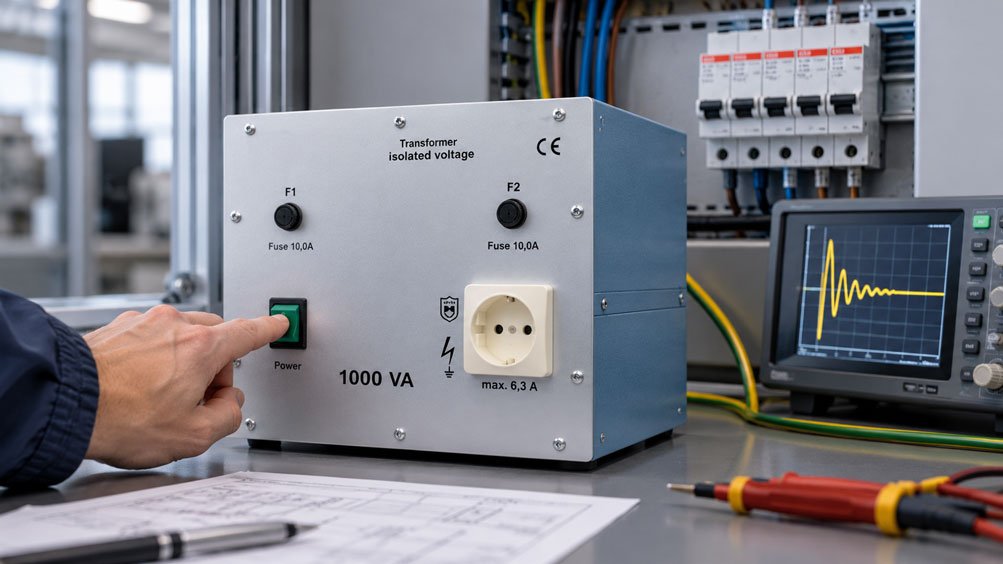
In an industrial test facility, an isolation transformer supplies several electrical measuring and testing instruments with a galvanically isolated AC voltage. The transformer has a rated power of 600 VA and operates at a mains voltage of 230 V. During normal operation, the current consumption remains within the intended range. Nevertheless, the upstream miniature circuit breaker occasionally trips when the transformer is switched on.
During another test, all secondary-side loads are initially disconnected. The transformer is then switched on again. Surprisingly, the circuit breaker also trips without any connected load.
A conventional short circuit or overload caused by connected loads therefore initially appears unlikely. Nevertheless, the current can briefly reach several times the normal operating current during switch-on.
The cause may be the magnetizing inrush current of the transformer. When the mains voltage is applied, a magnetic flux must build up in the iron core. Depending on the switching instant and the residual magnetization of the core, a particularly high magnetic flux can develop.
If the saturation limit of the core material is temporarily reached, the effective magnetizing inductance decreases. This can result in a high, frequently asymmetrical current pulse. This phenomenon can occur in transformers and is not automatically an indication of a defect.
However, the magnitude of the inrush current is not identical during every switching operation. It is influenced, among other factors, by the switching angle of the mains voltage, core remanence, transformer design, winding resistance and the impedance of the supplying network.
This explains why the same isolation transformer can be switched on several times without any problems, only to suddenly trip an upstream protective device during another switching operation.
Particularly in frequently switched test benches, larger isolation transformers, sensitive power supplies and installations with limited mains power capacity, this effect can cause recurring interruptions to operation.
For correct evaluation, it is essential to distinguish between normal rated current, short-duration magnetizing inrush current, secondary-side load starting current and an actual electrical fault.
The characteristics of the upstream protective device also play an important role. Miniature circuit breakers with B, C or D tripping characteristics have different electromagnetic tripping ranges. Fuses behave differently depending on their design and time-current characteristics.
However, simply replacing a repeatedly tripping protective device with one having a higher current rating or a slower tripping characteristic would be dangerous. The protective function for the wiring, transformer and connected electrical equipment must remain fully effective after any modification.
Suitable inrush current limitation can be the technically preferable solution in certain applications. This allows the transformer’s magnetization to build up in a more controlled manner or temporarily limits the initial current.
In addition, the transformer must be correctly sized for the connected loads. Rated power is normally specified in volt-amperes and must not be equated with active power in watts without considering the power factor.
A correctly sized isolation transformer must be able to handle both the continuous load current and the permissible short-duration loads. The mains impedance, voltage drop along supply cables, protection concept of the galvanically isolated secondary side and actual operating conditions must also be considered.
This technical article explains the causes of magnetizing inrush current and shows why it can also occur under no-load conditions. It describes the influence of remanence and switching angle, the characteristics of different protective devices and the technical options for limiting inrush current.
A detailed calculation example considers a 600 VA isolation transformer operating at 230 V. It shows how to calculate rated current, the difference between peak current and RMS current, the tripping ranges of different miniature circuit breakers and the influence of supply cable impedance on voltage drop.
The article also covers load behavior, primary- and secondary-side protective measures, EMC, galvanic isolation, measuring methods, diagnostics and suitable isolation and variable isolation transformers from the ICS Schneider Messtechnik product range.
Table of Contents
- Measurement Task and Typical Switching Problems with Isolation Transformers
- Operating Principle of an Isolation Transformer
- Distinguishing Magnetizing Current and Inrush Current
- Understanding Remanence, Switching Angle and Core Saturation
- Correctly Evaluating the Time Profile of Inrush Current
- B, C and D Tripping Characteristics of Miniature Circuit Breakers
- Fuses, Time-Current Characteristics and Selectivity
- Practical Example: Calculating Rated Current, Inrush Peak and Circuit Breaker Tripping
- Correctly Sizing Rated Power, Load Current and Power Reserve
- No-Load, Partial-Load, Full-Load and Secondary-Side Inrush Currents
- Mains Impedance, Cable Losses and Voltage Drop
- Inrush Current Limitation and Controlled Premagnetization
- Designing Primary-Side Overload and Short-Circuit Protection
- Secondary-Side Protective Measures and Galvanic Isolation
- EMC, Mains Disturbances and Sensitive Measurement Equipment
- Frequent Switching, Restarting and Thermal Loading
- Measuring Inrush Current Using Suitable Instruments
- Test Instruments, Measurement Uncertainty and Reproducible Measurement Conditions
- Electrical Safety and Relevant Standards
- Systematic Testing and Commissioning Procedure
- Typical Fault Symptoms and Targeted Diagnostics
- Suitable ICS Products for Galvanically Isolated Power Supplies
- Conclusion: Designing Inrush Current Management and Protection Together
- Frequently Asked Questions About Isolation Transformer Inrush Current
1. Measurement Task and Typical Switching Problems with Isolation Transformers
Isolation transformers are used in laboratories, test benches, workshops, electrical installations and industrial power supply systems.
They provide a galvanically isolated AC power supply and can therefore form part of an appropriate electrical protection or measurement concept.
1.1 Switching On an Unloaded Transformer
A transformer can draw a high primary current when switched on, even without a load connected to the secondary side.
This current results from the buildup of magnetic flux in the iron core.
High no-load inrush current is therefore not automatically an indication of a short circuit.
1.2 Intermittent Circuit Breaker Tripping
In some installations, the upstream protective device trips only occasionally.
Such behavior may be related to different switching instants and the magnetic history of the transformer core.
1.3 Tripping with a Connected Load
When an isolation transformer is switched on together with several loads, the magnetizing inrush current and the inrush currents of the connected equipment can overlap.
The resulting current loading must therefore be evaluated for the complete system.
1.4 Typical Applications
This issue is particularly relevant for:
- Electrical laboratory and testing workstations.
- Measurement and calibration systems.
- Industrial control cabinets.
- Automation systems.
- Power supplies for sensitive measuring instruments.
- Electrical safety test benches.
- Mains-isolated power supplies for experimental setups.
- Frequently switched industrial test systems.
- Power supplies provided by generators or UPS systems.
- Transformers with large magnetic core masses.
1.5 Objective of the Technical Investigation
The investigation is intended to determine whether a protective device trips due to a permissible inrush event, overload, short circuit or another electrical fault.
The necessary measures for transformer selection, protection and inrush current limitation can then be determined.
2. Operating Principle of an Isolation Transformer
An isolation transformer has primary and secondary windings that are electrically insulated from one another.
Energy is transferred magnetically through a common core.
2.1 Galvanic Isolation
In a properly designed isolation transformer, there is no direct conductive connection between the primary and secondary windings.
The secondary voltage is generated by electromagnetic induction.
2.2 Magnetic Flux
The applied AC voltage generates a time-varying magnetic flux in the iron core.
For an idealized winding:
u(t) = N · dΦ(t)/dt
Where:
- u(t) is the instantaneous winding voltage.
- N is the number of turns.
- Φ(t) is the magnetic flux.
- t is time.
2.3 Voltage Transformation
For an idealized transformer, the approximate relationship is:
U1/U2 = N1/N2
The ratio of the number of turns therefore determines the voltage transformation ratio.
2.4 Transformer with 230 V Primary and 230 V Secondary
An isolation transformer with 230 V primary and 230 V secondary voltage provides a galvanically isolated AC supply with nominally the same voltage.
It is not an automatic voltage regulator.
The actual output voltage can vary due to changes in mains voltage and load.
2.5 No-Load Operation
Even without a connected load, a no-load current flows during normal AC operation.
It includes the current required to magnetize the core and the active current component necessary to cover core losses.
2.6 Loaded Transformer
When a load is connected, current flows on the secondary side.
The resulting primary current component enables energy transfer from the mains supply to the load.
Winding and core losses must also be considered.
2.7 Difference from an Autotransformer
A conventional autotransformer uses winding sections that are electrically connected between the primary and secondary sides.
It therefore does not provide the galvanic isolation offered by a properly designed isolation transformer.
3. Distinguishing Magnetizing Current and Inrush Current
The term magnetizing current is frequently used for both the normal operating condition and the transient switching event.
A clear distinction is necessary for evaluation.
3.1 Normal Magnetizing Current
During steady-state AC operation, magnetic flux is maintained in the iron core.
A certain magnetizing current is required for this purpose.
Its magnitude depends on the core material, winding and operating voltage, among other factors.
3.2 Magnetizing Inrush Current
When the transformer is switched on, magnetic flux must build up from the core’s existing magnetic state.
This can cause a temporary asymmetry that results in a substantially higher current.
3.3 Inrush Current Under No-Load Conditions
Even when the secondary side of the transformer is unloaded, the magnetizing inrush current can be high.
It must therefore not be equated with the inrush current of a connected load.
3.4 Inrush Current of Connected Loads
Connected equipment can cause additional currents during startup.
Examples include charging DC-link capacitors or starting electric motors.
3.5 Superposition of Current Components
When the transformer and its connected loads are switched on simultaneously, different time-dependent current components can overlap.
The actual current waveform results from the complete electrical system.
3.6 Short-Circuit Current
Short-circuit current results from an electrical fault or an impermissible connection with a correspondingly low impedance.
It must be distinguished from the magnetizing inrush current that can occur during normal switching.
Both causes must be investigated carefully during troubleshooting.
4. Understanding Remanence, Switching Angle and Core Saturation
The magnitude of magnetizing inrush current is significantly influenced by the magnetic state of the transformer core at the moment of switching.
4.1 Remanence
Remanence refers to the magnetization that remains in the core material after the transformer has been switched off.
It depends on the magnetic history of the transformer.
4.2 Switching Angle
The AC mains voltage has a particular phase angle at every instant.
When the transformer is switched on, the magnetic flux begins to change according to the time integral of the applied voltage.
4.3 Switching at the Voltage Zero Crossing
Switching on near the voltage zero crossing can produce a particularly large initial magnetic flux excursion in a simple single-phase transformer.
This is related to the relationship between voltage and magnetic flux.
Conventional zero-crossing switching is therefore not automatically the best method for limiting transformer inrush current.
4.4 Switching Near the Voltage Peak
Under certain initial conditions, switching closer to the voltage peak can produce a more favorable initial magnetic flux profile.
However, the effect also depends on the existing remanence.
4.5 Core Saturation
If the magnetic flux exceeds the intended operating range of the core material, the core can become saturated.
In this condition, the effective magnetizing inductance decreases sharply.
As a result, the primary current can increase considerably.
4.6 Mains Impedance
The resulting inrush current is limited, among other factors, by winding resistance, leakage reactance and the impedance of the supplying power source.
Under otherwise identical conditions, a low-impedance supply can allow higher current peaks.
4.7 Different Switching Events
Because the switching angle and remanence are not identical during every switching operation, the current waveform can also vary.
A single successful switching attempt therefore does not reliably demonstrate that circuit breaker tripping will never occur under all permissible conditions.
5. Correctly Evaluating the Time Profile of Inrush Current
Magnetizing inrush current is a time-dependent electrical phenomenon.
Neither the maximum current value nor the normal operating current alone is sufficient for its evaluation.
5.1 Peak Current
The highest instantaneous current during switch-on is referred to as the peak current.
It is expressed, for example, in amperes as an instantaneous peak value.
5.2 RMS Value
The RMS value of an alternating current quantity describes its equivalent heating effect over a defined time interval.
For a sinusoidal current:
Ipeak = √2 · IRMS
However, this relationship does not generally apply to highly asymmetrical inrush current waveforms.
5.3 Inrush Current Pulse
The magnetizing inrush current can be significantly elevated, particularly during the first mains cycles.
Its subsequent time profile depends on the transformer, mains impedance and operating conditions.
5.4 Asymmetrical Current Waveform
The inrush current is frequently not symmetrical around zero.
It can contain a pronounced DC component or corresponding transient asymmetry.
5.5 Current Harmonics
Temporary magnetic saturation can produce a non-sinusoidal current waveform containing pronounced harmonics.
5.6 Decay Over Time
As the transient process progresses, the additional magnetizing current component generally decreases.
The time required depends on transformer design and application.
5.7 Importance for Protective Devices
A fuse or miniature circuit breaker does not respond exclusively to an inrush current factor stated in a data sheet.
Duration, waveform, thermal preloading and the tripping characteristic of the specific protective device are also relevant.
5.8 Measuring the Switching Event
Time-resolved recording of the primary current can be useful for reliable diagnosis.
A conventional current display with a slow update rate may not fully capture very short current peaks.
6. B, C and D Tripping Characteristics of Miniature Circuit Breakers
Miniature circuit breakers have different tripping characteristics that can be relevant when supplying transformers.
6.1 Thermal Tripping
Thermal tripping primarily provides protection against prolonged overload.
Its response depends on current magnitude and duration.
6.2 Electromagnetic Tripping
Electromagnetic tripping responds to high currents and is primarily intended to provide rapid disconnection in the event of a short circuit.
The corresponding tripping range depends on the selected characteristic.
6.3 B Characteristic
For miniature circuit breakers with a B characteristic according to IEC/EN 60898-1, the characteristic electromagnetic tripping range lies between three and five times the rated current.
6.4 C Characteristic
For the C characteristic, this range lies between five and ten times the rated current.
This characteristic can be useful in appropriately designed circuits with higher inrush currents.
6.5 D Characteristic
For the D characteristic, the characteristic electromagnetic tripping range lies between ten and twenty times the rated current.
Its use requires a suitably designed electrical installation and protection system.
6.6 Tripping Characteristic Ranges
For a miniature circuit breaker with a rated current of 6 A, the characteristic multiples result in the ranges shown in the table.
| Characteristic | Range Relative to In | Example at 6 A | Technical Significance |
|---|---|---|---|
| B | 3 to 5 × In | 18 to 30 A | More sensitive to higher short-duration currents |
| C | 5 to 10 × In | 30 to 60 A | Higher magnetic tripping range for suitable circuits with inrush peaks |
| D | 10 to 20 × In | 60 to 120 A | For appropriately designed circuits with high short-duration current loading |
6.7 Correctly Comparing Inrush Peaks
A measured short-duration peak current must not be compared uncritically and directly with these tripping ranges.
The standardized tripping ranges refer to defined AC test conditions. Actual magnetizing inrush current, by contrast, can be very short and highly asymmetrical.
For reliable evaluation, the complete current waveform must be considered together with the specific device characteristics.
6.8 Maintaining Protective Functions
Changing from a B characteristic to C or D must not be done solely to eliminate unwanted tripping during startup.
Conductor cross-section, installation conditions, short-circuit current and required disconnection conditions must continue to be satisfied, among other factors.
7. Fuses, Time-Current Characteristics and Selectivity
In addition to miniature circuit breakers, fuses can be used to protect transformer and power supply circuits.
7.1 Time-Current Behavior
For fuses, melting time depends on the current load.
A high current acting for a short time can be evaluated differently from a lower overload sustained over a longer period.
7.2 Time-Delay Fuses
Certain time-delay fuses can withstand short inrush current pulses without operating.
Their actual suitability is determined by their time-current characteristic and manufacturer specifications.
7.3 I²t Assessment
The integral of current squared over time is relevant to the thermal effect of a time-dependent current:
I²t = ∫ i(t)² dt
The exact relationship between current loading and fuse behavior depends on the particular fuse.
7.4 Short-Duration Current Pulse
A high peak current of very short duration can produce a different thermal load from the same current magnitude sustained for a longer period.
Evaluation must therefore not be based solely on peak current.
7.5 Fuse Rated Current
The rated current of a fuse must be suitable for the wiring and intended operating current.
A larger fuse must not simply be selected to eliminate switching problems.
7.6 Selectivity
Where protective devices are connected in series, it must be established which device should operate in the event of a fault.
Selectivity depends on the protective devices used, short-circuit current and their characteristics.
7.7 Manufacturer Specifications
The primary- and secondary-side protective measures recommended by the transformer manufacturer are particularly important for selection.
These recommendations must be coordinated with the actual circuit and applicable installation requirements.
8. Practical Example: Calculating Rated Current, Inrush Peak and Circuit Breaker Tripping
A laboratory uses a single-phase isolation transformer with a rated power of 600 VA and a galvanically isolated output voltage of 230 V.
In terms of rated voltages and continuous power, the technical configuration corresponds, for example, to the ICS 5357.2 series.
Several idealized calculations are performed to investigate an upstream miniature circuit breaker that trips occasionally.
8.1 Initial Data and Assumptions
The following conditions apply to the calculation example:
- Single-phase isolation transformer.
- Rated apparent power: 600 VA.
- Rated primary voltage: 230 V AC.
- Rated secondary voltage: 230 V AC.
- Mains frequency: 50 Hz.
- Upstream miniature circuit breaker: 6 A.
- Tripping characteristics to be compared: B, C and D.
- Assumed peak inrush current: 32 A.
- Assumed duration of the highest current range: A few milliseconds.
- Example current measurement over an additional interval: 15 A RMS over 10 ms.
- One-way length of the assumed copper supply cable: 15 m.
- Supply conductor cross-section: 1.5 mm².
- Resistivity of copper: 0.0178 Ω · mm²/m at 20 °C.
- A simplified ohmic conductor model for the voltage drop calculation.
The assumed inrush current values are freely selected. They are not guaranteed inrush current specifications of the ICS 5357.2 transformer.
8.2 Calculating Rated Primary Current
For a single-phase transformer, the calculated rated current is determined from the rated apparent power and primary voltage:
I1,N ≈ SN/U1,N
For the transformer:
I1,N = 600 VA / 230 V
I1,N ≈ 2.61 A
This value represents an idealized rated current derived from apparent power.
The actual primary current drawn at a given load additionally depends on losses, no-load current and power factor.
8.3 Calculating Rated Secondary Current
At a nominal secondary voltage of 230 V:
I2,N = 600 VA / 230 V
I2,N ≈ 2.61 A
The 600 VA isolation transformer used can therefore supply a corresponding rated load of approximately 2.61 A at the intended rated secondary voltage.
The actual permissible loading is determined by the specific manufacturer specifications.
8.4 Rated Current of the Upstream Protective Device
For this example, an upstream miniature circuit breaker with a rated current of 6 A is assumed.
The calculated primary rated current of approximately 2.61 A is below this current rating.
However, this neither proves that a 6-A miniature circuit breaker is suitable for the specific installation nor guarantees that it will not trip during switch-on.
8.5 Assumed Peak Inrush Current
A hypothetical peak current of 32 A is assumed for the investigation.
The ratio of this instantaneous peak current to the rated primary current is:
32 A / 2.61 A ≈ 12.3
Iinrush,peak/I1,N ≈ 12.3
However, this dimensionless value compares an instantaneous peak with a nominal RMS value.
It is therefore not a directly interpretable standardized tripping factor for the miniature circuit breaker.
8.6 Comparison with the Normal Sinusoidal Current Peak
If the idealized rated primary current is considered sinusoidal:
IN,peak = √2 · I1,N
IN,peak = √2 · 2.61 A
IN,peak ≈ 3.69 A
The assumed peak inrush current of 32 A therefore corresponds approximately to:
32 A / 3.69 A ≈ 8.7
8.7 times the sinusoidal rated current peak
This is also only a calculated comparison and does not demonstrate any particular tripping behavior.
8.7 B Characteristic at 6 A
For the characteristic electromagnetic tripping range of a B6 miniature circuit breaker:
Lower limit: 3 · 6 A = 18 A
Upper limit: 5 · 6 A = 30 A
B6: 18 to 30 A
8.8 C Characteristic at 6 A
For a C6 miniature circuit breaker:
Lower limit: 5 · 6 A = 30 A
Upper limit: 10 · 6 A = 60 A
C6: 30 to 60 A
8.9 D Characteristic at 6 A
For a D6 miniature circuit breaker:
Lower limit: 10 · 6 A = 60 A
Upper limit: 20 · 6 A = 120 A
D6: 60 to 120 A
8.10 Why a Direct Comparison Is Insufficient
The assumed peak current of 32 A is numerically greater than 30 A.
However, this does not mean that a B6 miniature circuit breaker will necessarily trip in this example.
The characteristic multiples of rated current refer to the corresponding standardized test conditions. A short, asymmetrical magnetizing current pulse has a different waveform.
Actual tripping behavior can therefore only be evaluated using suitable device characteristics and the relevant inrush current-time curve.
8.11 Hypothetical I²t Model
It is additionally assumed that a time-resolved measurement produces an RMS current of 15 A over an interval of 10 ms.
For this measurement interval:
I²t = IRMS² · Δt
I²t = 15² A² · 0.010 s
I²t = 2.25 A²s
This value describes the current-squared time loading over the interval being considered.
It must not be compared with an arbitrary limit of a fuse or miniature circuit breaker without further manufacturer information.
8.12 Calculating Supply Cable Resistance
For the simplified calculation, a single-phase copper supply cable with a one-way length of 15 m and a conductor cross-section of 1.5 mm² is considered.
Because both outgoing and return conductors are included, the total conductive length is:
Ltotal = 2 · 15 m
Ltotal = 30 m
The ohmic conductor resistance is:
RL = ρ · L/A
RL = 0.0178 · 30 / 1.5 Ω
RL = 0.356 Ω
8.13 Voltage Drop at Rated Current
At the calculated rated current of approximately 2.61 A, the simplified ohmic model gives:
ΔU = 2.61 A · 0.356 Ω
ΔU ≈ 0.93 V
The voltage drop corresponds to approximately 0.4 % of the assumed mains voltage of 230 V.
8.14 Voltage Drop at Increased Current Loading
If a current of 20 A is used for a separate calculation:
ΔU = 20 A · 0.356 Ω
ΔU = 7.12 V
This value illustrates the possible influence of the supply cable on voltage under higher current loading.
However, it does not describe the actual time-dependent voltage profile during an asymmetrical transformer inrush pulse.
8.15 Power Loss in the Supply Cable
At the idealized rated current, the ohmic power loss is:
PL = I² · RL
PL = 2.61² · 0.356 W
PL ≈ 2.43 W
In the model considered, this power is dissipated as heat in the outgoing and return conductors.
8.16 Summary of Results
| Calculated Parameter | Assumption or Calculation | Result |
|---|---|---|
| Transformer rated apparent power | Freely selected reference value | 600 VA |
| Rated primary voltage | Instrument rated value | 230 V AC |
| Rated secondary voltage | Instrument rated value | 230 V AC |
| Calculated rated primary current | 600 VA / 230 V | 2.61 A |
| Calculated rated secondary current | 600 VA / 230 V | 2.61 A |
| Hypothetical peak inrush current | Freely selected assumption | 32 A |
| Sinusoidal rated current peak | √2 · 2.61 A | 3.69 A |
| Ratio of current peaks | 32 / 3.69 | 8.7 |
| Magnetic B6 tripping range | 3 to 5 · 6 A | 18 to 30 A |
| Magnetic C6 tripping range | 5 to 10 · 6 A | 30 to 60 A |
| Magnetic D6 tripping range | 10 to 20 · 6 A | 60 to 120 A |
| Hypothetical 10 ms RMS value | Freely selected assumption | 15 A |
| I²t over 10 ms | 15² · 0.010 | 2.25 A²s |
| One-way cable length | Freely selected | 15 m |
| Conductor cross-section | Freely selected | 1.5 mm² |
| Outgoing and return conductor resistance | 0.0178 · 30 / 1.5 | 0.356 Ω |
| Ohmic voltage drop at 2.61 A | 2.61 · 0.356 | 0.93 V |
| Ohmic voltage drop at 20 A | 20 · 0.356 | 7.12 V |
| Ohmic conductor power loss at 2.61 A | 2.61² · 0.356 | 2.43 W |
8.17 Interpretation
The example demonstrates that the normal rated current of a transformer can be considerably lower than its short-duration inrush current.
A hypothetical peak inrush current of 32 A must be considered when evaluating an upstream 6-A miniature circuit breaker.
However, this peak value alone is not sufficient to predict tripping reliably.
The current waveform, time profile, protective device characteristic and operating conditions must also be known.
8.18 Limitations of the Calculation
The calculated rated currents and conductor resistances are based on the specified idealized assumptions.
The inrush current and current-squared time loading values are explicitly hypothetical.
In particular, they are not measured or manufacturer-guaranteed inrush current specifications of the ICS 5357.2.
The example does not constitute approval for using any particular miniature circuit breaker or fuse.
The specific selection of protective devices must comply with the applicable requirements.
9. Correctly Sizing Rated Power, Load Current and Power Reserve
Correct sizing of an isolation transformer begins with determining the actual electrical power required.
9.1 Apparent Power
Transformers are normally specified by their rated apparent power in volt-amperes.
For a single-phase system:
S = URMS · IRMS
9.2 Active Power
Active power is expressed in watts.
For sinusoidal voltages and currents:
P = URMS · IRMS · cos φ
Under non-sinusoidal conditions, distortion components must also be considered.
9.3 Power Factor
A load with a lower power factor may require a higher RMS current for the same active power.
The actual apparent power is therefore relevant when sizing the transformer.
9.4 Continuous Power
The sum of the connected continuous loads must remain within the permissible transformer loading.
Ambient temperature, cooling and operating duration must be considered.
9.5 Short-Term Load Capacity
Some transformers are designed for defined short-duration overloads.
Such specifications refer to the conditions intended by the manufacturer and must not be equated with magnetizing inrush current.
9.6 Power Reserve
Sufficient reserve capacity may be useful for future expansions and load fluctuations.
However, the reserve must not be selected solely on the basis of an arbitrary percentage.
9.7 Larger Transformer
A transformer with a higher rated power can supply a larger continuous load current.
However, a larger transformer does not automatically eliminate magnetizing inrush current problems.
Depending on its design, even higher inrush current peaks may occur.
9.8 Frequency and Input Voltage
The transformer must be suitable for the mains voltage and frequency.
Operation at excessive voltage or insufficient frequency can increase magnetic flux in the iron core.
The voltage-to-frequency ratio is therefore relevant to the design.
10. No-Load, Partial-Load, Full-Load and Secondary-Side Inrush Currents
An isolation transformer behaves differently under various loading conditions.
10.1 No-Load Operation
During no-load operation, no useful power is delivered to a connected load.
Nevertheless, magnetizing current and core losses still occur.
10.2 Partial Load
At partial load, a correspondingly lower load current flows.
The actual output voltage and losses depend on the transformer design.
10.3 Full Load
At rated load, the transformer must be able to deliver its specified continuous power under the stated conditions.
10.4 Power Supplies with Rectifiers
Many connected measuring and control instruments contain rectifiers and DC-link capacitors.
These can cause additional charging current pulses during startup.
10.5 Motor Loads
Electric motors can draw significantly higher currents during startup than during steady-state operation.
These load currents must be considered during design.
10.6 Simultaneous Switching
If the transformer and several loads are switched on simultaneously, the resulting current loading can be greater than when the transformer is switched on without a load.
10.7 Staggered Switching
Switching on connected loads at different times can help limit additional startup currents in suitable installations.
However, the magnetizing inrush current of the transformer itself must still be considered separately.
10.8 Diagnostics Through Load Disconnection
Comparing switching events with and without connected loads can be useful during troubleshooting.
However, such tests must only be carried out using a safe and approved procedure.
11. Mains Impedance, Cable Losses and Voltage Drop
The characteristics of the supplying power source influence the switching event.
11.1 Mains Impedance
Mains impedance includes the ohmic and inductive components of the supplying system.
It affects the available current and voltage profile.
11.2 Long Supply Cables
Long connecting cables have higher resistance and corresponding impedance.
At increased current, this can cause additional voltage drop.
11.3 Voltage Dip
A high inrush current can cause a short-duration voltage dip under certain conditions.
Its actual magnitude depends on mains impedance and the current waveform.
11.4 Sensitive Measurement Equipment
Measuring instruments, controllers and communication systems can be sensitive to short supply voltage interruptions or dips.
The power supply must therefore be evaluated with regard to such mains events.
11.5 Generator Supply
Generators may have limited short-term current capacity.
Transformer inrush current can therefore have a greater impact on their output voltage under certain conditions.
11.6 UPS Supply
UPS systems have their own current limiting and overload functions.
Their suitability for supplying transformers must be verified using the relevant manufacturer specifications.
11.7 Voltage Drop Under Continuous Load
Normal conductor resistance also causes voltage drop and electrical losses.
The supply cable must therefore be designed for continuous current and the required voltage quality.
11.8 Not a Substitute for Protection Calculations
A simplified ohmic voltage drop calculation does not replace a complete short-circuit current, disconnection condition or mains impedance calculation.
12. Inrush Current Limitation and Controlled Premagnetization
Different technical methods are available to limit magnetizing inrush current.
12.1 Inrush Current Limitation
An inrush current limiter reduces the initial current when the transformer is switched on.
Its purpose is to reduce unwanted protective device tripping and additional mains loading.
12.2 Series Resistor
A suitable series resistor can limit the initial current.
Once the intended transient process has finished, it can be bypassed in an appropriately designed system.
The design must take electrical and thermal loading into account in particular.
12.3 NTC Resistors
An NTC resistor has a temperature-dependent resistance characteristic.
In suitable applications, it can limit inrush current.
However, its effectiveness depends on temperature, switching frequency and actual operating conditions.
12.4 Repeated Switching
An NTC resistor that is still warm may have a different resistance during restart than when cold.
This effect must be considered in frequently switched installations.
12.5 Electronic Inrush Current Limitation
Electronic circuits can influence the switching process in a controlled manner.
The actual effect and suitability depend on the device design.
12.6 Premagnetization
Suitable premagnetization can influence the initial magnetic state of the transformer core before full energization.
Under appropriate conditions, this can reduce high magnetizing inrush current peaks.
12.7 Controlled Switching
Suitable control methods can influence the switching instant or magnetization profile in a controlled manner.
The effect depends on transformer design and magnetic history.
12.8 Protective Functions Remain Necessary
Inrush current limitation does not replace the necessary short-circuit protection or other required overload and protective measures.
12.9 ICS Instruments with Corresponding Functions
ICS offers the 5357.5 isolation transformer with a premagnetization switch.
According to its product description, the 5315.0 variable isolation transformer features electronic inrush current limitation.
For a specific application, the available functions and suitability of the complete power supply must be evaluated separately.
13. Designing Primary-Side Overload and Short-Circuit Protection
Primary-side protection must be suitable for the transformer and supplying circuit.
13.1 Supply Cable Protection
Cables must be protected against impermissible overload and short circuits.
The design depends on conductor cross-section, material, installation method and current-carrying capacity, among other factors.
13.2 Transformer Protection Requirements
Depending on the transformer design, special requirements for overload or temperature protection may apply.
The manufacturer specifications are decisive.
13.3 Considering Inrush Current
The primary-side protective device must be suitable for the expected permissible switching events.
At the same time, it must provide the necessary protection in the event of actual faults.
13.4 Miniature Circuit Breakers
Selection includes rated current, tripping characteristic, breaking capacity and circuit requirements.
A suitable miniature circuit breaker must operate reliably under the actual mains conditions.
13.5 Fuses
Fuses may be provided depending on the transformer and protection concept.
Selection must be based on the time-current characteristic and expected current loading.
13.6 Short-Circuit Current at the Installation Location
The available short-circuit current must be known or appropriately determined when selecting a protective device.
13.7 Disconnection Conditions
The required disconnection conditions must remain satisfied even if the tripping characteristic is changed.
13.8 No Impermissible Increase in Protection Ratings
A protective device must not simply be replaced with one having a higher rating because it occasionally trips during startup.
The cause must be identified and a complete electrical evaluation performed.
14. Secondary-Side Protective Measures and Galvanic Isolation
For isolation transformers, primary- and secondary-side protective measures must be considered separately.
14.1 Galvanically Isolated Secondary Side
The secondary winding is electrically insulated from the primary winding.
The actual protective effect results from the complete intended protection system.
14.2 Protective Electrical Separation
Protective electrical separation is a defined protective measure with corresponding requirements.
Simply using an isolation transformer does not automatically mean that all requirements of this protective measure have been met.
14.3 Protective Conductor of the Transformer Housing
A Class I isolation transformer has a corresponding protective conductor terminal or a protective conductor connection provided for that purpose.
Galvanic isolation of the secondary winding does not mean that an equipment housing requiring protective earthing may be operated without a protective conductor.
14.4 Earthing Reference of the Secondary Side
The secondary side can be treated differently depending on the application and protection concept.
Whether a connection to earth or other potentials is intended or permissible must be clarified for the specific circuit.
An unintended earth connection can change the characteristics of the intended protective separation.
14.5 Multiple Loads
When several loads are connected to an isolated secondary supply, additional protection requirements may apply.
The installation must meet the corresponding requirements.
14.6 Secondary-Side Overload
The secondary winding can also be thermally endangered by excessive loading.
The required protection depends on the transformer and connection concept.
14.7 Secondary-Side Short Circuit
A secondary-side short circuit is influenced by the characteristics of the transformer and the protective devices installed.
The necessary disconnection must be ensured through the specific design.
14.8 Isolation Transformers and Safety Transformers
The requirements for general-purpose isolation transformers according to IEC 61558-2-4 and safety isolating transformers according to IEC 61558-2-6 must be distinguished.
A conventional 230-V isolation transformer does not automatically provide a SELV or PELV supply.
15. EMC, Mains Disturbances and Sensitive Measurement Equipment
Electromagnetic compatibility can play an important role when supplying sensitive measurement and automation equipment.
15.1 Stray Magnetic Field
Transformers produce stray magnetic fields due to their design.
Under certain conditions, these can influence sensitive measuring arrangements nearby.
15.2 Switching Transients
The switching process can cause a temporary change in mains current.
Combined with existing mains impedance, this can produce voltage fluctuations.
15.3 Effects on Measuring Instruments
Sensitive electronic equipment can respond to short-duration supply voltage dips or disturbances.
The actual immunity depends on the specific devices.
15.4 Galvanic Isolation
Galvanic isolation can provide advantages in terms of potential separation for suitable measurement applications.
However, it does not automatically eliminate all electromagnetic interference.
15.5 Capacitive Coupling
Parasitic capacitances can exist between the primary and secondary windings.
High-frequency interference components can be coupled through these capacitances.
15.6 Shielding Winding
Certain transformers may be equipped with additional shielding measures.
Whether these are present and what effect they provide must be checked for the specific configuration.
15.7 Cable Routing
The routing of power and signal cables can influence interference behavior.
Suitable separation distances, shielding and equipotential bonding measures may be necessary.
15.8 Overall EMC Assessment
Selecting an isolation transformer does not replace a complete EMC assessment of the installation concerned.
16. Frequent Switching, Restarting and Thermal Loading
Switching frequency can be relevant for certain transformer and inrush current limiting concepts.
16.1 Occasional Switching
A transformer in laboratory equipment that is rarely switched on has different requirements from a regularly switched power supply system.
16.2 Frequent Switching Events
Repeated inrush currents can place stress on protective devices, contacts and components of an inrush current limiter.
16.3 Switching Off and Restarting
Residual magnetization can remain in the core after switch-off.
The next switching event can therefore produce a different current waveform.
16.4 NTC Behavior
The temperature dependence of NTC resistors must be considered when they are used for inrush current limitation.
After a short off period, an NTC resistor that is still warm can have a significantly lower resistance than during a cold start.
16.5 Electronic Limitation
Electronic inrush current limiters may be suitable for certain repeated switching operations.
However, permissible switching frequency must be verified using the device specifications.
16.6 Condition of Protective Devices
Following repeated tripping events, the thermal condition of protective devices may differ.
This can influence actual tripping behavior.
16.7 Switching Contacts
Contactors and switches must be suitable for the inrush currents that occur.
Selection must not be based exclusively on the steady-state transformer rated current.
16.8 Operating Strategy
Suitable switching management can improve operational reliability in frequently switched installations.
However, the actual solution must be compatible with the complete electrical installation.
17. Measuring Inrush Current Using Suitable Instruments
Suitable current measurement is required to diagnose inrush current problems.
17.1 Multimeter
A conventional multimeter can measure normal operating current.
However, very short inrush current peaks may not be displayed correctly when the instrument has a slow update rate.
17.2 Current Clamp
Suitable current clamps can measure current consumption without directly interrupting the circuit.
Actual suitability depends on measuring range, bandwidth and measurement function.
17.3 Inrush Function
Certain current clamps have a dedicated inrush measurement function.
The measurement duration and evaluation method used must be suitable for the current waveform being investigated.
17.4 Current Transformer with Oscilloscope
A suitable combination of current sensor and time-resolved measuring instrument can display the actual inrush current waveform.
The sensor must be sufficiently suitable for the current peak and its frequency components.
17.5 Peak and RMS Values
Measurement should clearly distinguish between instantaneous current peaks, RMS values over defined intervals and continuous operating current.
17.6 Current-Time Recording
For a detailed evaluation of circuit breaker tripping, a current-time recording is often more informative than a single maximum value.
17.7 Multiple Switching Tests
Under permissible and approved test conditions, several switching events may be required to investigate variations.
The tests must not subject the transformer or electrical installation to impermissible loading.
17.8 Safe Measurement
Measurements on mains circuits must be performed using suitable instruments and in compliance with the relevant safety requirements.
Unsuitable test leads or measurement methods must not be used.
18. Test Instruments, Measurement Uncertainty and Reproducible Measurement Conditions
The evaluation of inrush current also depends on the characteristics of the measuring instruments used.
18.1 Measuring Range
The measuring instrument must be capable of recording both normal operating current and possible inrush current peaks.
Overloading the measuring input can distort the indicated peak value.
18.2 Dynamic Bandwidth
Insufficient measurement bandwidth can attenuate or shift rapid current components in time.
18.3 Sampling Rate
For digital recording, the sampling rate must be sufficient for the current components of interest.
Analog signal bandwidth and anti-aliasing filtering must also be considered.
18.4 Peak Measurement
The operation of a peak measurement function depends on the instrument’s internal measurement method.
Depending on the instrument, a value designated as inrush may be defined differently from an actual instantaneous peak value.
18.5 Calibration
Calibration of a current measuring instrument documents its measurement deviations under defined conditions.
The calibration must be suitable for the intended measurement task.
18.6 Dynamic Measurement Uncertainty
A static or low-frequency current calibration does not automatically demonstrate accuracy for highly transient current waveforms.
18.7 Reproducibility
When evaluating several switching events, mains voltage, transformer condition and switching conditions must be documented.
18.8 Overall Evaluation
For reliable diagnostics, the measuring instrument, measurement method, current waveform and protective device characteristics must be considered together.
19. Electrical Safety and Relevant Standards
Isolation transformers are frequently used in safety-related and measurement applications.
Correct electrical design is therefore essential.
19.1 IEC 61558-1
IEC 61558-1 contains general safety requirements and tests for transformers and corresponding power supply units within its scope.
19.2 IEC 61558-2-4
IEC 61558-2-4 covers particular requirements and tests for general-purpose isolation transformers and corresponding power supply units.
19.3 IEC 61558-2-6
IEC 61558-2-6 covers safety isolating transformers and power supply units incorporating such transformers.
Its scope differs from that of a conventional isolation transformer.
19.4 EN 60204-1
For the electrical equipment of machines, the requirements of EN 60204-1 must be considered where applicable to the specific installation.
19.5 IEC/EN 60898-1
IEC/EN 60898-1 describes, among other things, corresponding miniature circuit breakers with characteristic tripping ranges.
19.6 IEC/EN 60947-2
Other circuit breakers and protective devices for corresponding industrial applications may fall under IEC/EN 60947-2.
19.7 Protection Against Electric Shock
Galvanic isolation of a secondary winding does not prevent hazardous electrical contact under all circumstances.
The complete protective measure must be designed according to the intended system.
19.8 Protection Class I
A Class I isolation transformer requires the designated protective conductor connection.
This applies regardless of the galvanic isolation of its secondary winding.
19.9 Secondary-Side Protection Conditions
Connecting multiple loads, any possible earth connection and the selection of protective devices must be evaluated according to the intended protective measure.
19.10 Work on Mains Circuits
Testing, changing fuses and working on electrical connections may only be carried out by appropriately qualified personnel under the required protective conditions.
20. Systematic Testing and Commissioning Procedure
If circuit breakers repeatedly trip during startup, the complete supply circuit should be investigated systematically.
The following procedure provides technical guidance and must be adapted to the specific installation.
- Define the measurement task: Clarify which instruments are supplied and what purpose galvanic isolation is intended to serve.
- Identify the transformer: Record manufacturer, model, rated power, voltages and frequency.
- Check manufacturer documentation: Evaluate information on inrush current, overload capability, protective measures and switching operation.
- Record the supply system: Determine earthing system, supply voltage, frequency and relevant mains impedance.
- Document primary-side protection: Identify fuse type, rated current, tripping characteristic and breaking capacity.
- Check supply cables: Evaluate conductor cross-section, installation method, length and protection conditions.
- Record secondary-side loads: Determine the connected loads and their continuous power requirements.
- Consider load starting currents: Evaluate any additional inrush currents of connected equipment separately.
- Calculate total apparent power: Consider rated load and possible future expansion.
- Determine transformer rated current: Derive primary and secondary currents from the corresponding rated values.
- Document the fault behavior: Record whether tripping occurs during every start or only occasionally.
- Establish safe test conditions: Implement the necessary electrical protective measures according to an approved procedure.
- Perform visual inspection: Check housing, connections, fuses, cables and any visible thermal damage.
- Check the protection concept: Consider primary- and secondary-side protection and protective measures.
- Select suitable current measuring equipment: Use a method capable of adequately recording transient inrush current.
- Record the current waveform: Document peak value, time profile and suitable RMS intervals.
- Record mains voltage: If necessary, investigate the simultaneous voltage profile.
- Compare loaded and no-load behavior: Only using an appropriately safe and approved test setup.
- Evaluate the tripping characteristic: Compare the measured current waveform with the characteristic of the specific protective device.
- Exclude or investigate overload and short circuits: Evaluate electrical fault causes using a suitable procedure.
- Evaluate inrush current limitation: Select a suitable technical solution based on the actual current loading.
- Evaluate changes to protective devices: Change rated current or tripping characteristic only after a complete protection and network calculation.
- Verify protective effectiveness: Check cable, transformer and disconnection requirements.
- Perform repeat testing: Verify the effectiveness of any changes under intended operating conditions.
- Document the results: Record transformer, load, mains conditions, protective devices, measured values and evaluation in a traceable manner.
This procedure supports diagnostics but does not replace any required electrical design or safety approval.
21. Typical Fault Symptoms and Targeted Diagnostics
Different fault symptoms can occur when isolation transformers are switched on.
The causes must be investigated based on the electrical and magnetic operating conditions.
| Fault Symptom | Possible Cause | Suitable Diagnostic Action |
|---|---|---|
| Circuit breaker trips only occasionally during switch-on | Different switching angles and existing remanence | Evaluate several safely performed inrush measurements and the tripping characteristic |
| Tripping occurs even without connected loads | Magnetizing inrush current or a fault in the transformer or primary circuit | Investigate no-load inrush current and electrical fault causes |
| Tripping occurs only with a connected load | Additional load starting currents or overload | Check load current, switching sequence and transformer power |
| Transformer operates normally after switch-on | Short-duration inrush current pulse | Compare transient current waveform with protective device characteristic |
| Protective device trips after prolonged operation | Possible continuous overload, thermal loading or electrical fault | Investigate continuous current, temperature and protection conditions |
| Significant voltage drop during switch-on | High inrush current combined with relevant mains impedance | Record current and voltage waveforms simultaneously |
| Controller restarts when transformer is switched on | Supply voltage dip or other mains disturbance | Check supply quality and interference immunity |
| Inrush current differs after short off periods | Remanence or temperature condition of a limiter | Consider magnetic and thermal initial conditions |
| NTC limitation is less effective during restart | NTC is still warm and has a lower resistance | Check cooling time and suitability for the switching frequency |
| Transformer becomes unusually hot during continuous operation | Overload, cooling problem, unsuitable voltage or frequency | Evaluate load, mains conditions and temperature according to manufacturer instructions |
| Unusually loud humming | Magnetostriction, mechanical resonance or unsuitable magnetic operating conditions | Check mounting, operating voltage, frequency and temperature |
| After changing from B to C, the circuit breaker no longer trips during startup | Different electromagnetic tripping range | Also verify short-circuit and disconnection conditions without exception |
| Secondary voltage drops significantly under load | Overload, transformer internal impedance or cable losses | Measure load apparent power and voltage drop |
| UPS shuts down when the transformer starts | Current limitation or overload response of the UPS | Check compatibility between UPS and transformer |
| Unusually high current persists after switch-on | Overload, incorrect connection conditions or electrical defect | Safely take the installation out of service and have the causes professionally investigated |
The listed causes are possible diagnostic approaches and do not constitute definitive fault identification.
In particular, repeated circuit breaker tripping must not be ignored without proper investigation of the cause.
22. Suitable ICS Products for Galvanically Isolated Power Supplies
ICS Schneider Messtechnik offers various isolation transformers, variable isolation transformers and other power supply components for laboratory, testing and industrial applications.
Selection depends in particular on primary voltage, secondary voltage, required apparent power, continuous current, protection concept and expected switching conditions.
22.1 ICS 5357.2 – 600 VA Isolation Transformer
The ICS 5357.2 is an isolation transformer housed in a benchtop enclosure with a galvanically isolated secondary side.
It is intended for suitable laboratory, testing and power supply applications.
Documented features include:
- Rated primary voltage of 230 V AC.
- Rated frequency of 50 to 60 Hz.
- Secondary voltage of 230 V AC.
- Rated apparent power of 600 VA.
- Continuous output current of 2.6 A.
- Short-time load capacity of 690 VA.
- Galvanically isolated secondary side.
- Protection Class I.
- Ingress protection IP30.
- Convection cooling.
- Primary connection via mains cable with protective contact plug.
- Two-pole output socket.
- Fuses on the front panel.
- Illuminated mains switch.
- Benchtop design.
The 5357.2 is suitable for corresponding applications requiring a galvanically isolated 230-V AC power supply.
Both the connected load and actual switching conditions must be considered during design.
No binding maximum magnetizing inrush current can be derived from the rated current of approximately 2.6 A.
The suitability of upstream protection must therefore be verified for the specific installation.
Further Information: ICS 5357.2 at ICS Schneider Messtechnik
22.2 ICS 5357.3 – 800 VA Isolation Transformer
The ICS 5357.3 is a galvanically isolated transformer designed for a higher rated apparent power.
Documented features include:
- Rated primary voltage of 230 V AC.
- Frequency range of 50 to 60 Hz.
- Secondary voltage of 230 V AC.
- Rated apparent power of 800 VA.
- Continuous output current of 3.47 A.
- Short-time load capacity of 920 VA.
- Galvanically isolated secondary side.
- Convection cooling.
- Benchtop enclosure.
- Protection Class I.
- Ingress protection IP30.
- Mains connection with protective contact plug.
- Two-pole output socket.
- Fuses on the front panel.
- Illuminated mains switch.
The 5357.3 is an interesting option for applications with correspondingly higher power requirements.
The inrush current behavior of this configuration must also be evaluated independently of its normal continuous load capacity.
Higher transformer power is not an automatic solution to unwanted circuit breaker tripping.
Further Information: ICS 5357.3 at ICS Schneider Messtechnik
22.3 ICS 5357.4 – 1,000 VA Isolation Transformer
The ICS 5357.4 is an isolation transformer with a rated power of 1,000 VA and a galvanically isolated output voltage.
Documented features include:
- Input voltage of 230 V AC.
- Mains frequency of 50 to 60 Hz.
- Output voltage of 230 V AC.
- Rated apparent power of 1,000 VA.
- Continuous output current of 4.35 A.
- Short-time load capacity of 1,150 VA.
- Galvanically isolated secondary side.
- Protection Class I.
- Ingress protection IP30.
- Convection cooling.
- Benchtop enclosure.
- Front-mounted fuses.
- Illuminated mains switch.
The transformer may be suitable for larger laboratory and testing workstation power supplies.
Its rated power of 1,000 VA describes its intended continuous load capacity.
It must not be equated with the short-duration magnetizing inrush current.
Further Information: ICS 5357.4 at ICS Schneider Messtechnik
22.4 ICS 5357.5 – 2,300 VA Isolation Transformer with Premagnetization Switch
The ICS 5357.5 is a higher-power galvanically isolated transformer in a benchtop enclosure.
The premagnetization switch mentioned in its product description is particularly relevant to the inrush current issue discussed here.
Documented features include:
- Rated primary voltage of 230 V AC.
- Frequency range of 50 to 60 Hz.
- Secondary voltage of 230 V AC.
- Rated apparent power of 2,300 VA.
- Continuous output current of 10 A.
- Short-time load capacity of 2,600 VA.
- Galvanically isolated secondary side.
- Premagnetization switch.
- Front-mounted thermal-magnetic circuit breakers.
- Illuminated mains switch or corresponding indicator function.
- Convection cooling.
- Protection Class I.
- Ingress protection IP30.
- Benchtop design.
The premagnetization switch is particularly interesting for applications in which high inrush currents can cause operational problems.
Its actual effect and intended operating conditions must be checked against the manufacturer’s instructions.
The premagnetization switch does not replace the necessary primary- and secondary-side protection.
Further Information: ICS 5357.5 at ICS Schneider Messtechnik
22.5 ICS 5315.0 – Variable Isolation Transformer with Electronic Inrush Current Limitation
The ICS 5315.0 combines a galvanically isolated power supply with an adjustable output voltage.
It is intended for suitable laboratory and test bench applications requiring variable voltage.
Documented features include:
- Rated primary voltage of 230 V AC.
- Frequency range of 50 to 60 Hz.
- Adjustable output voltage from 2 to 250 V AC.
- Maximum output current of 10 A.
- Continuous power rating of 2,500 VA.
- Short-time load capacity of 2,875 VA.
- Galvanically isolated secondary side.
- Electronic inrush current limitation.
- Three thermal-magnetic circuit breakers on the front panel.
- Convection cooling.
- Protection Class I.
- Ingress protection IP30.
- Benchtop design.
- Mains indicator light.
The 5315.0 is particularly interesting when variable AC voltage is required in addition to galvanic isolation.
Electronic inrush current limitation can be advantageous for corresponding supply and switching applications.
Nevertheless, the upstream protective device must be designed according to actual operating conditions.
A variable isolation transformer must also be distinguished from a conventional variable autotransformer, since galvanic isolation is maintained in the corresponding variable isolation transformer design.
Further Information: ICS 5315.0 at ICS Schneider Messtechnik
22.6 ICS 5357 Series – Isolation Transformers in Different Power Classes
The ICS 5357 series comprises galvanically isolated fixed-voltage transformers in different power classes.
The product range includes, among others:
- 5357.0 with 250 VA.
- 5357.1 with 400 VA.
- 5357.2 with 600 VA.
- 5357.3 with 800 VA.
- 5357.4 with 1,000 VA.
- 5357.5 with 2,300 VA.
Versions for other primary-side voltages are also available for corresponding configurations.
The instruments are intended for suitable applications requiring a galvanically isolated AC power supply.
Selection must be based on the required output voltage, load apparent power, continuous load capacity and protection concept.
The product series mainly comprises benchtop instruments for laboratory and testing applications. Their design must not be equated with a transformer intended for direct DIN-rail mounting in a control cabinet without verification.
Further Information: ICS Isolation Transformers
22.7 Variable Isolation Transformers for Flexible Test Voltages
In addition to fixed-voltage isolation transformers, ICS offers various variable isolation transformers.
Depending on the configuration, these can provide a variable AC voltage with a galvanically isolated output.
They are suitable for corresponding measurement and testing applications requiring both potential separation and voltage adjustment.
Particular attention must be paid to:
- Primary voltage and frequency.
- Maximum output voltage.
- Output current.
- Continuous power.
- Short-time load capacity.
- Available inrush current limitation.
- Primary- and secondary-side protective functions.
- Enclosure design and connection type.
- Electrical protective measures.
Further Information: ICS Variable Isolation Transformers
22.8 Technical Selection of a Suitable Isolation Transformer
The following information should be available for a specific inquiry:
- Primary voltage.
- Mains frequency.
- Required secondary voltage.
- Single-phase or three-phase power supply.
- Required continuous apparent power in VA.
- Normal primary and secondary load currents.
- Type of connected loads.
- Additional load starting currents.
- Frequency of switching operations.
- Existing primary-side protection.
- Fuse current rating and tripping characteristic.
- Available mains impedance or short-circuit current conditions.
- Cable lengths and conductor cross-sections.
- Required primary- and secondary-side protective measures.
- Desired inrush current limitation.
- Required galvanic isolation.
- Laboratory, test bench or control cabinet installation.
- Ambient temperature and cooling conditions.
- Required EMC characteristics.
- Any required test and documentation records.
Based on this information, the suitable transformer configuration and protection or switching concept can be evaluated.
Power Supply Technology at ICS Schneider Messtechnik
23. Conclusion: Designing Inrush Current Management and Protection Together
When an isolation transformer is switched on, a significantly higher primary current can briefly occur than during normal operation.
This current results primarily from the buildup of magnetic flux in the iron core.
The magnitude of magnetizing inrush current depends, among other factors, on the switching angle, residual core magnetization and the electrical characteristics of the transformer and power supply.
It is particularly important to understand that high inrush current can occur even without a secondary-side load connected.
Circuit breaker tripping during startup is therefore not automatically evidence of an overloaded load or a short circuit.
At the same time, tripping must not be dismissed as a harmless switching event without further investigation.
The causes must be investigated systematically.
When evaluating inrush current, a distinction must be made between instantaneous peak current and RMS current over a defined time interval.
A highly asymmetrical current pulse cannot simply be treated as a sinusoidal continuous current.
This is particularly important when comparing currents with protective device tripping characteristics.
Miniature circuit breakers with B, C and D characteristics have different electromagnetic tripping ranges.
The B characteristic responds at lower multiples of rated current than the C or D characteristic.
However, a slower tripping characteristic must not be selected solely to prevent unwanted tripping during startup.
The required cable and fault protection conditions must remain satisfied after any modification.
The calculation example illustrates this problem using a 600 VA isolation transformer at 230 V.
The calculated rated current is approximately 2.61 A.
A freely assumed peak inrush current of 32 A is significantly higher.
For a 6-A miniature circuit breaker, the characteristic magnetic tripping ranges are 18 to 30 A for B, 30 to 60 A for C and 60 to 120 A for D.
These figures provide an initial technical indication but do not reliably predict the actual tripping behavior of a short asymmetrical inrush current pulse.
For this purpose, the current-time curve and the characteristics of the specific protective device must be considered.
Mains impedance is another influencing factor.
At high inrush current, relevant supply cable impedance can cause a temporary voltage drop.
Sensitive measuring and control instruments can respond to such supply voltage dips under certain conditions.
Transformer selection must therefore also consider mains voltage, frequency, cable length and connected loads.
When sizing the transformer, a distinction must also be made between rated apparent power in volt-amperes and actual active power consumption.
Although a larger transformer can supply a greater continuous load, it does not automatically solve problems caused by high magnetizing inrush currents.
Controlled inrush current limitation can be advantageous in suitable applications.
This applies particularly to frequently switched test benches, larger transformers and power supply systems with limited short-term current capacity.
ICS Schneider Messtechnik offers, for example, the 5357.5 with a premagnetization switch.
According to its product description, the 5315.0 variable isolation transformer provides electronic inrush current limitation.
The effectiveness and suitability of such functions must be verified for the particular application.
Furthermore, the electrical protective effect of galvanic isolation must not be overestimated.
An isolation transformer does not automatically replace all primary- and secondary-side protective measures.
In particular, protective electrical separation as a defined protective measure must be distinguished from simply using a transformer with separate windings.
The protection class of the equipment housing, required earthing connections and number or type of connected loads must be considered accordingly.
Reliable design therefore includes the transformer, switching device, primary-side protective devices, secondary-side protection, connected loads and the characteristics of the power supply.
The key conclusion is: High inrush current in an isolation transformer does not automatically indicate an overload or electrical fault. It can be caused by remanence, an unfavorable switching angle and temporary core saturation. For reliable operation, the inrush current profile, tripping characteristic, transformer power and complete electrical protection concept must be evaluated together. Suitable inrush current limitation can be a better solution than increasing the fuse rating without proper evaluation.
24. Frequently Asked Questions About Isolation Transformer Inrush Current
24.1 Why Does an Isolation Transformer Draw High Current When Switched On?
When the transformer is switched on, magnetic flux must build up in its iron core. Depending on the switching angle and existing remanence, a particularly large magnetic flux excursion can develop. If the core becomes temporarily saturated, the effective magnetizing inductance decreases and a high inrush current can flow. This phenomenon does not automatically indicate an electrical fault.
24.2 Can an Isolation Transformer Cause High Inrush Current Without a Connected Load?
Yes. Magnetizing inrush current occurs during the buildup of magnetic flux and can therefore arise even when the secondary side is unloaded. Additional loads are not required for this effect. No-load switching behavior can therefore be particularly informative during troubleshooting.
24.3 Why Does the Circuit Breaker Trip Only Occasionally During Startup?
Inrush current can vary from one switching event to another. Important factors include the switching instant within the mains voltage cycle and the residual magnetization of the iron core. As a result, the current may remain unproblematic during one switching event but become significantly higher during another.
24.4 What Does Remanence Mean in a Transformer?
Remanence refers to the magnetization that can remain in the magnetic core after the transformer has been switched off. It influences the initial conditions during the next startup. Depending on its direction and the switching angle, it can cause a larger or smaller initial magnetic flux excursion.
24.5 Why Can Switching at the Voltage Zero Crossing Be Unfavorable?
Magnetic flux depends on the time integral of the applied voltage. In a simple single-phase transformer, switching near the voltage zero crossing can produce a particularly large initial flux excursion. The actual effect also depends on the residual magnetization. Zero-crossing switching is therefore not automatically a suitable method of limiting transformer inrush current.
24.6 How High Can the Inrush Current of an Isolation Transformer Be?
Inrush current can briefly reach several times the normal primary current. However, no universally applicable value can be specified for all transformers. The actual magnitude depends on core material, design, winding resistance, mains impedance, remanence and switching angle. Manufacturer specifications or suitable measurements are required for design.
24.7 Does High Inrush Current Automatically Mean There Is a Short Circuit?
No. High magnetizing inrush current can be a normal transient phenomenon. However, short circuits, overloads and electrical defects can also cause high currents. Distinguishing between these causes requires suitable diagnostics. Protective devices that trip repeatedly must therefore not be ignored without investigating the cause.
24.8 What Is the Difference Between Inrush Current and Rated Current?
Rated current describes the current at a defined rated load. Inrush current can be temporarily much higher during startup. It frequently has a strongly time-dependent and asymmetrical waveform. In addition to its magnitude, the duration and applicable measurement definition must therefore be considered.
24.9 Which Circuit Breaker Characteristic Is Suitable for an Isolation Transformer?
The suitable characteristic depends on the transformer, inrush current waveform and complete protection concept. B, C and D miniature circuit breakers have different electromagnetic tripping ranges. However, a C or D characteristic must not be recommended universally. Short-circuit current, cable protection and the required disconnection conditions must be verified for the specific installation.
24.10 What Is the Difference Between B and C Characteristics?
For miniature circuit breakers according to IEC/EN 60898-1, the characteristic electromagnetic tripping range of B lies between three and five times the rated current, while C lies between five and ten times the rated current. The C characteristic is therefore less sensitive to certain higher inrush currents. However, whether it may be used depends on the complete electrical protection calculation.
24.11 Can I Simply Replace a B6 Miniature Circuit Breaker with a C6?
No. Such a replacement must not be made without verification. The different tripping characteristic changes the conditions for rapid disconnection at high fault currents. It must be checked whether the required disconnection conditions, short-circuit current and cable protection remain satisfied.
24.12 Can a Time-Delay Fuse Help with Inrush Current?
A suitably selected time-delay fuse can withstand short inrush current pulses under certain conditions. However, selection must be based on the actual time-current characteristic and protection requirements. A larger or slower fuse must not be installed without an appropriate electrical evaluation.
24.13 What Is an Inrush Current Limiter for Transformers?
An inrush current limiter is a technical device that reduces the initial current when a transformer is switched on. Suitable series resistors, temperature-dependent resistors or electronic methods can be used for this purpose. The specific solution must match the transformer, its power rating and intended switching frequency.
24.14 What Does Premagnetization Achieve?
Suitable premagnetization influences the initial magnetic state of the iron core before full energization. Under appropriate conditions, this can produce a more favorable initial magnetic flux excursion and reduce inrush current. The actual effect depends on the technology used and the transformer.
24.15 Can a Larger Isolation Transformer Prevent Circuit Breaker Tripping?
Not automatically. A larger transformer can supply a greater continuous electrical load. However, its magnetizing inrush current can also be high. If tripping is caused by core magnetization inrush current, simply increasing rated power is not a reliable solution. The causes must be investigated specifically.
24.16 How Is the Inrush Current of an Isolation Transformer Measured?
Suitable measuring systems must be capable of accurately recording short and potentially asymmetrical current waveforms. These include certain current clamps with an appropriate inrush function or time-resolved measuring systems with a suitable current sensor. Measurement bandwidth, measuring range and the distinction between peak current and RMS current are decisive.
24.17 Does an Isolation Transformer Automatically Improve Electrical Safety?
An isolation transformer provides galvanic isolation between the primary and secondary sides. However, the actual electrical protective effect depends on the complete system. In particular, protective measures for the equipment housing, secondary side and connected loads must be considered. Galvanic isolation alone does not replace a complete safety concept.
24.18 Which ICS Isolation Transformer Is Suitable for Problems with High Inrush Current?
Selection depends on voltage, power, load and existing protection. ICS offers, for example, isolation transformers from the 5357 series with power ratings from 250 to 2,300 VA. The 5357.5 features a premagnetization switch. The 5315.0 variable isolation transformer has electronic inrush current limitation and also provides adjustable output voltage. Whether these instruments are suitable for the specific application must be verified against the actual electrical operating and protection conditions.