


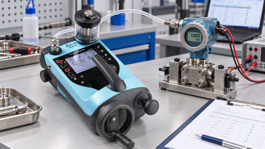
An industrial pressure transmitter was sent for repair due to an incorrect indication. After replacing an electronic module, the instrument is functioning again. Plausible pressure values appear on the display, and the 4–20 mA output responds to pressure changes.
But is the transmitter already suitable for use in production again?
A successful functional test initially confirms only that the tested instrument functions are working. It does not automatically demonstrate whether the measuring instrument still meets the required accuracy.
After a repair, functionality, metrological condition and approval for use must therefore be evaluated separately.
Depending on the extent of the repair, a visual inspection, electrical safety test, leak test, multipoint calibration or complete functional test may be required.
This article explains the differences, describes a traceable testing procedure and uses a pressure transmitter to demonstrate how measurement deviation, measurement uncertainty and permissible tolerance interact when determining whether an instrument can be released for use.
Table of Contents
- Evaluating Measuring Instruments After Repair
- Repair, Calibration, Adjustment and Release
- Determining the Scope of Repair and Testing
- Documenting the Initial Condition and As-Found Results
- Visual Inspection and Mechanical Checks
- Electrical and Functional Tests
- Selecting Suitable Reference Instruments
- Practical Example: Pressure Transmitter After Repair
- Correctly Considering Measurement Uncertainty
- Tolerance and Decision Rules
- Selecting Calibration Points and Measuring Span
- Stabilization and Repeatability
- Hysteresis and Return to Zero
- Electrical Signals and Communication
- Leak Tightness and Mechanical Resistance
- Temperature Dependence of Measurement Deviations
- Calibration Certificate and Repair Report
- Traceability and Accredited Calibration
- Impact on Previous Measurement Results
- Reviewing the Calibration Interval After Repair
- Release Procedure and Typical Errors
- Suitable ICS Products
- Conclusion
- Frequently Asked Questions
1. Evaluating Measuring Instruments After Repair
Measuring instruments can be damaged by ageing, overloading, impact, moisture or electronic defects.
After a repair, it must be verified whether the original characteristics or those required for further use have been restored.
The necessary extent of testing depends particularly on the work performed and the importance of the measuring instrument for process quality and safety.
2. Repair, Calibration, Adjustment and Release
These terms describe different activities:
- Repair: Correction of a technical defect.
- Functional test: Verification of specified instrument functions.
- Calibration: Determination of the relationship between reference values and instrument indications, including the associated measurement uncertainty.
- Adjustment: Modification of instrument settings to improve measurement performance.
- Verification: Demonstration that specified requirements have been fulfilled.
- Release: Documented decision authorizing the instrument to be used again for a specific measurement task.
A calibration certificate does not automatically constitute an unrestricted authorization to return an instrument to service.
3. Determining the Scope of Repair and Testing
Replacing a display may require different tests from replacing a pressure sensing cell or an analog electronic module.
If a metrologically relevant component is replaced, the affected measurement characteristics normally need to be verified again.
For a pressure transmitter, this includes, for example, the zero point, characteristic curve, measuring span, output signal and, where applicable, temperature effects.
| Repair or Modification | Important Tests | Special Consideration |
|---|---|---|
| Display or control element replaced | Indication, operation, parameters | Check metrological effects |
| Measuring cell or sensor replaced | Complete calibration over the relevant measuring range | Measurement characteristics may have changed |
| Analog electronic module replaced | Input and output signals, scaling, linearity | Check the electrical measurement chain |
| Process connection or seal repaired | Leak tightness, materials, mechanical function | Suitable pressure test required |
| Firmware or parameterization changed | Configuration, signals, diagnostics, function | Document software version |
| Housing damage repaired | Mechanical condition, ingress protection and electrical safety where applicable | Observe approval conditions |
The table provides general guidance. The actual tests required depend on the instrument, scope of repair and application requirements.
4. Documenting the Initial Condition and As-Found Results
The condition of the instrument as received should be documented before repair.
If the measuring instrument is still sufficiently functional and can be tested safely, measurements can be recorded before the intervention.
These so-called As-Found results help assess the potential impact of previous measurement deviations on tests already performed.
For a completely failed instrument, such calibration may not be possible. In this case, the condition must be documented accordingly.
5. Visual Inspection and Mechanical Checks
Before metrological testing, the housing, connections, seals and operating elements are inspected.
For pressure measuring instruments, damaged process connections, deformed diaphragms and indications of overpressure are particularly relevant.
The instrument must be clearly identifiable by manufacturer, model, serial number and measuring range.
6. Electrical and Functional Tests
Depending on the measuring instrument, the supply voltage, current consumption, display, operating elements and interfaces are checked.
For a process pressure transmitter, the analog output signal and, where applicable, HART communication are particularly important parts of the functional check.
Where electrical safety requirements are relevant, the specified test procedures must be considered.
A correct output signal at only one test point does not replace verification over the complete measuring span.
7. Selecting Suitable Reference Instruments
The reference instrument must be suitable for the measuring range, pressure reference type or physical quantity, and required measurement uncertainty.
For a pressure transmitter, a suitable precision pressure controller or portable pressure calibrator can be used, for example.
Valid calibration information, documented traceability and sufficiently low measurement uncertainty for the intended task are important.
The relationship between tolerance and reference uncertainty must be assessed according to the intended testing procedure and decision rule.
8. Practical Example: Pressure Transmitter After Repair
A hypothetical pressure transmitter with a measuring range of 0 to 10 bar and a 4–20 mA output has been repaired.
The following calibration examines whether the instrument once again operates within the specified tolerance.
8.1 Initial Data
- Measuring range: 0 to 10 bar gauge pressure.
- Output signal: 4 to 20 mA.
- Permissible measurement deviation: ±0.10 bar.
- Assumed expanded measurement uncertainty of calibration: U = 0.04 bar.
- Test points: 0 / 2.5 / 5 / 7.5 / 10 bar.
- Simplified decision rule: |Deviation| + U ≤ 0.10 bar.
All values are hypothetical assumptions. The decision rule is an example of an agreed rule and is not a universally prescribed release method.
8.2 Ideal Output Signal
For the linear characteristic:
I = 4 mA + 16 mA · p / 10 bar
At 5 bar:
I = 4 mA + 16 mA · 5 / 10
I = 12.00 mA
8.3 Converting Measured Current into Pressure
The reverse calculation is:
pIndicated = (I – 4 mA) · 10 bar / 16 mA
At a reference pressure of 10 bar, the repaired instrument initially provides 20.12 mA.
The corresponding indicated value is:
p = (20.12 – 4) · 10 / 16
p = 10.075 bar
The measurement deviation is therefore:
e = 10.075 – 10.000
e = +0.075 bar
8.4 Evaluating Tolerance and Measurement Uncertainty
The measurement deviation of 0.075 bar alone is within the specified tolerance of ±0.10 bar.
According to the example conservative decision rule:
|e| + U = 0.075 + 0.04
|e| + U = 0.115 bar
This exceeds the acceptance limit of 0.10 bar.
Result: No positive conformity decision according to this decision rule.
8.5 Testing Across the Measuring Span
| Reference Pressure | Ideal Signal | Measured Signal | Pressure Deviation | Evaluation Including U |
|---|---|---|---|---|
| 0 bar | 4.00 mA | 4.02 mA | +0.0125 bar | Pass |
| 2.5 bar | 8.00 mA | 8.03 mA | +0.0188 bar | Pass |
| 5 bar | 12.00 mA | 12.06 mA | +0.0375 bar | Pass |
| 7.5 bar | 16.00 mA | 16.09 mA | +0.0563 bar | Pass |
| 10 bar | 20.00 mA | 20.12 mA | +0.0750 bar | Fail |
8.6 Adjustment and Re-Testing
Following suitable adjustment, a current of 20.04 mA is measured at 10 bar in this example.
This gives:
p = (20.04 – 4) · 10 / 16 = 10.025 bar
The deviation is +0.025 bar.
Including the assumed measurement uncertainty:
0.025 + 0.04 = 0.065 bar
This individual test point now meets the specified decision rule.
However, all required test points and additional instrument functions must subsequently be successfully verified again before the instrument can be released for use.
8.7 Interpreting the Result
The example demonstrates that a measurement deviation within the specified instrument tolerance does not necessarily lead to a positive conformity decision.
Measurement uncertainty and the agreed decision rule can influence the result.
Final release is only possible after testing and evaluation of all application-relevant requirements have been completed.
9. Correctly Considering Measurement Uncertainty
Every calibration involves measurement uncertainty. This results from factors including the reference instrument, resolution, repeatability and environmental conditions.
When evaluating a tolerance, it must be defined how measurement uncertainty is taken into account.
A small instrument deviation alone is therefore not sufficient proof of conformity.
10. Tolerance and Decision Rules
A decision rule defines the conditions under which a measurement result is assessed as conforming or nonconforming.
ILAC G8 provides guidance on different decision rules and the use of guard bands.
If a statement of conformity is required, the specification and applicable decision rule must be clearly established.
A decision based on a reduced acceptance interval is not automatically mandatory for every measurement task.
11. Selecting Calibration Points and Measuring Span
Calibration points should adequately cover the intended operating range.
For a pressure transmitter, the zero point and 25%, 50%, 75% and 100% of the measuring span may be tested, for example.
Particularly important operating or alarm values may require additional test points.
The test program must be appropriate for the instrument, procedure and actual requirements.
12. Stabilization and Repeatability
After repair, measured values may temporarily be unstable due to thermal or mechanical influences.
Suitable stabilization must therefore take place before readings are recorded.
Repeated measurements help determine whether the instrument operates reproducibly.
Strongly fluctuating values may indicate incomplete repairs, electrical problems or an unsuitable testing procedure.
13. Hysteresis and Return to Zero
For pressure measuring instruments, testing with increasing and decreasing pressure points may be necessary.
This allows differences between the ascending and descending measurement sequences to be detected.
The return to zero after exposure to higher pressure also provides important information about mechanical and metrological performance.
Testing only with increasing pressure may fail to detect certain errors.
14. Electrical Signals and Communication
Following repairs to electronic modules, signal inputs, outputs and relevant interfaces must be checked.
For a 4–20 mA pressure transmitter, loop power supply, current output and scaling are particularly important.
For instruments with HART or other digital interfaces, the corresponding communication functions may also need to be tested.
Instrument parameters should be compared with the intended configuration after repair.
15. Leak Tightness and Mechanical Resistance
If pressure-containing components, diaphragms or seals have been repaired, a suitable leak or pressure test may be necessary.
The test conditions must be adapted to the instrument design.
A successful pressure calibration does not automatically confirm leak tightness under all permissible operating conditions.
Process connections, threads and sealing surfaces must also be considered.
16. Temperature Dependence of Measurement Deviations
Calibration at room temperature does not necessarily describe measurement performance over the entire permissible operating temperature range.
Following replacement of measuring cells or electronic components, an additional temperature test may therefore be required.
This is particularly relevant for measuring instruments exposed to significant temperature fluctuations during operation.
The extent of testing depends on manufacturer specifications and the required measurement accuracy.
17. Calibration Certificate and Repair Report
For traceable release, repair work and metrological testing should be documented separately.
The repair report describes the identified defect and the work performed.
The calibration certificate documents the calibration results, including the required information on measurement conditions, references and measurement uncertainty.
Clear instrument identification, the tested measuring range and assignment to the actual condition after repair are particularly important.
18. Traceability and Accredited Calibration
Metrological traceability is established through a documented, unbroken chain of suitable calibrations with associated uncertainties.
Factory calibration may be sufficient for certain applications, provided the required evidence is available.
Accredited calibration according to DIN EN ISO/IEC 17025 may be appropriate or contractually required, particularly where more demanding documentation requirements apply.
The accreditation must cover the relevant measurand, measuring range and procedure within its specific scope.
A calibration laboratory is not automatically accredited for every measurand simply because it holds DAkkS accreditation.
19. Impact on Previous Measurement Results
If a measuring instrument was outside the permissible tolerance before repair, it may be necessary to determine which previous measurements could have been affected.
The last known valid calibration condition, usage history and identified fault are relevant for this assessment.
A successful repair does not retrospectively correct previous measurement results.
In quality-critical applications, a documented evaluation of products or processes already inspected may be necessary.
20. Reviewing the Calibration Interval After Repair
The next calibration date should not be determined exclusively by an unchanged standard interval.
Following major repairs, additional intermediate checks or a temporarily shortened interval may be appropriate.
ILAC G24:2022 addresses methods for establishing and reviewing recalibration intervals.
Decisive factors include stability, operating conditions, scope of repair, previous drift behavior and the risks associated with incorrect measurement results.
21. Release Procedure and Typical Errors
The instrument should only be returned to service once the specified tests have been successfully completed and the results evaluated.
A practical release procedure includes:
- Completion of repair and instrument identification.
- Verification of mechanical and electrical functions.
- Calibration of the relevant measurands.
- Conformity assessment according to the specified decision rule.
- Verification of additional application requirements.
- Documented release by the responsible authorized party.
Typical errors include releasing an instrument based solely on a repair note, incomplete calibration points, outdated parameters or a calibration certificate without the required tolerance assessment.
Responsibility for the operational use of the measuring instrument lies with the designated organization.
22. Suitable ICS Products
ICS Schneider Messtechnik offers calibration instruments and software for testing, calibrating and documenting repaired industrial measuring equipment.
| Product | Important Functions | Typical Application |
|---|---|---|
| Druck DPI610E | Integrated pressure generation, pressure measurement, mA and HART | Portable testing of pressure transmitters |
| Druck DPI620G Genii | Electrical and temperature-related signals, modular pressure testing | Multifunction process calibration |
| Druck PACE5000E | Precise automatic pressure generation and control with suitable modules | Laboratory and workshop calibration |
| WIKA CPH7000 | Pressure testing, electrical signals, optional pressure generation | Servicing and calibration of process instruments |
| Druck 4Sight2 | Calibration scheduling, documentation and instrument history | Measuring equipment management and calibration reports |
22.1 Druck DPI610E
The DPI610E combines pressure measurement and pressure generation with electrical calibration functions and HART communication.
Suitable versions generate pneumatic pressures up to 35 bar or hydraulic pressures up to 1,000 bar.
This allows pressure transmitters to be tested at multiple calibration points after repair.
Druck DPI610E – Product Information
22.2 Druck DPI620G Genii
The DPI620G is a modular multifunction calibrator for electrical, temperature and pressure-related testing applications.
Depending on the configuration, it supports current, voltage, resistance, frequency and HART communication, among other functions.
For pressure testing, suitable pressure modules and, where required, an appropriate pressure station are added.
Druck DPI620G Genii – Product Information
22.3 Druck PACE5000E
The PACE5000E is a modular precision pressure controller for laboratory and workshop applications.
With suitable modules, it enables stable, reproducible pressure control for multipoint calibrations.
Integration into automated testing procedures is particularly beneficial.
Druck PACE5000E – Product Information
22.4 WIKA CPH7000
The WIKA CPH7000 is a portable process calibrator for pressure measuring instruments, transmitters and suitable pressure switches.
Depending on the configuration, pressure measurement, electrical signal functions, pressure generation and documenting test procedures are available.
WIKA CPH7000 – Product Information
22.5 Druck 4Sight2
The 4Sight2 calibration software supports the management of measuring instruments, calibration schedules and documented test results.
It is particularly suitable for recurring calibration procedures and tracking instrument histories.
The actual documentation and release functions depend on the license, configuration and system used.
Druck 4Sight2 – Product Information
Additional Calibration Equipment at ICS Schneider Messtechnik
23. Conclusion
After repair, a measuring instrument must not only function again but also be suitable for its intended application.
The required scope of testing depends on the repair performed, instrument characteristics and quality requirements.
Following metrologically relevant repairs, recalibration is generally advisable. For a reliable conformity decision, tolerances, measurement deviations and the specified decision rule must be considered.
As-Found and As-Left data improve traceability and, where necessary, enable evaluation of previous measurement results.
A repaired measuring instrument should only be returned to service once its required functions have been tested, compliance with the metrological requirements has been demonstrated and its release has been documented.
24. Frequently Asked Questions
24.1 Is Recalibration Required After Every Repair?
Not automatically. The decisive factors are whether the repair may affect metrological characteristics and which requirements apply to the measuring instrument.
24.2 Is a Successful Functional Test Sufficient?
Usually not for metrologically relevant repairs. A functional test does not replace the required verification of measurement accuracy.
24.3 What Is the Difference Between Calibration and Adjustment?
Calibration determines measurement performance. Adjustment changes instrument settings to improve that performance.
24.4 What Does As-Found Mean?
As-Found describes the documented condition of a measuring instrument before adjustment or intervention, provided this condition can be determined safely and metrologically.
24.5 What Does As-Left Mean?
As-Left describes the documented condition after completion of the intended work, for example following repair and adjustment.
24.6 Is DAkkS-Accredited Calibration Mandatory After Repair?
Not generally. It may be required by contractual, normative, internal or legal requirements.
24.7 Can Factory Calibration Be Sufficient?
Yes, provided the requirements for measurement scope, uncertainty, traceability and documentation are fulfilled.
24.8 What Must Be Included in a Calibration Certificate?
Among other information, clear instrument identification, calibration results, measurement conditions and the required details concerning measurement uncertainty.
24.9 What Is a Decision Rule?
It defines how measurement uncertainty is taken into account when assessing compliance with a specification.
24.10 Why Is Measurement Uncertainty Important for Release?
Because a measured value close to the tolerance limit can only be assessed to a limited extent without considering uncertainty.
24.11 Which Calibration Points Should Be Tested?
The test points must adequately cover the relevant operating range. For pressure transmitters, several points across the measuring span are frequently used.
24.12 Must Hysteresis Also Be Tested?
If it is relevant to the instrument and measurement task, test points should be checked under increasing and decreasing applied conditions.
24.13 Is Calibration Required After Sensor Replacement?
When a metrologically relevant sensing cell is replaced, appropriate recalibration is normally required to demonstrate suitability.
24.14 Who Is Authorized to Release a Measuring Instrument?
The responsible, appropriately authorized party within the established quality or operational procedure.
24.15 What Happens if the Instrument Remains Outside Tolerance?
Release for the original measurement task is then not possible. Further adjustment, repair or a separately assessed restriction of use may be considered.
24.16 Must the Calibration Interval Be Changed After Repair?
Not always. However, following major repairs, reassessment or temporary shortening of the interval may be appropriate.
24.17 Can Previous Measurements Be Affected?
Yes. If relevant deviations existed before the repair, an evaluation of previous test results may be necessary.
24.18 What Information Does ICS Need for a Testing or Calibration Inquiry?
The required information includes manufacturer, instrument model, measuring range, serial number, fault description, scope of repair, desired calibration points, tolerances and the required type of calibration documentation.