


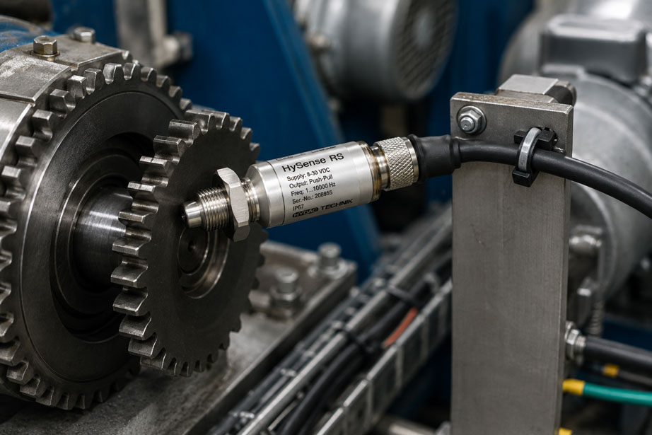
A speed sensor may appear suitable for 10.000 min⁻¹ and still reach its frequency limit at a significantly lower rotational speed. The decisive factor is not only the speed of the shaft, but also how many pulses the sensor generates per revolution. With a gear wheel featuring 60 detected teeth, a speed of 6.000 min⁻¹ already produces 6.000 Hz.
This pulse frequency must not only be handled by the sensor itself. Signal converters, frequency counters, PLC inputs, input filters and evaluation software must also be fast enough. At the same time, the number of pulses per revolution should not be unnecessarily low if low rotational speeds are to be measured with good resolution and a short update time.
When designing a speed measurement system, rotational speed, PPR, number of teeth, maximum frequency and required resolution must therefore be considered together. Changing just one of these parameters directly affects the entire measurement chain.
Suitable sensors and measuring instruments are available from ICS Schneider under Force, Weighing, Speed, Torque and Vibration Sensors and specifically under Speed Sensors and Speed Measuring Instruments.
For fast industrial frequency signals, ICS Schneider offers, for example, the HySense RS500 with a frequency range of approximately 1 … 10.000 Hz. How air gap, target wheel and signal quality should additionally be checked is explained in the technical article Speed sensor loses pulses: correctly check air gap, target wheel and switching frequency.
Table of Contents
- Why rotational speed and pulse frequency are two different quantities
- What does PPR mean for a speed sensor?
- When does the number of teeth correspond to PPR?
- Calculate rotational speed, PPR and frequency
- Typical frequencies at different PPR values
- Correctly determine the maximum input frequency
- Calculate maximum rotational speed from the frequency limit
- Minimum rotational speed and minimum frequency
- How PPR influences speed measurement resolution
- Measurement window and update time
- Frequency counting or period measurement?
- Rising edge, falling edge and quadrature evaluation
- Correctly design PLC and counter inputs
- Why input filters can suppress pulses
- The slowest component limits the measurement chain
- Systematically select PPR
- Practical example: 60-tooth wheel on a test bench
- Practical example: low rotational speed with high resolution
- Typical errors in PPR and frequency design
- Commission and test the speed measurement chain
- Suitable speed and frequency measurement technology from ICS Schneider
- Conclusion
- FAQ
Why rotational speed and pulse frequency are two different quantities
A rotating shaft initially has only a mechanical rotational speed. Typical units are:
min⁻¹
or:
rpm
The speed sensor, however, converts this into an electrical signal. Depending on the measurement principle, for example:
- a tooth on a gear wheel,
- a bore,
- a magnet,
- a reflective mark,
- a pole pair,
- an encoder track
can generate one or more evaluable signal transitions.
This produces a pulse frequency in:
Hz = pulses per second
A rotational speed of 3.000 min⁻¹ therefore does not automatically correspond to 3.000 Hz.
With one pulse per revolution, 3.000 min⁻¹ produces only:
50 Hz
With 60 pulses per revolution, however, it produces:
3.000 Hz
The frequency load on the electronics is therefore determined jointly by rotational speed and pulse count.
What does PPR mean for a speed sensor?
PPR usually stands for:
Pulses Per Revolution
meaning:
pulses per revolution
A sensor with:
1 PPR
generates one pulse per complete revolution.
At:
60 PPR
60 pulses are generated per revolution.
More PPR means more information per revolution
This can be particularly advantageous at low rotational speeds. The evaluation system receives a new pulse more frequently and can detect speed changes more quickly.
At the same time, however, the frequency increases proportionally with PPR.
A high PPR therefore does not automatically improve the measurement. It also increases the requirements placed on:
- sensor,
- signal transmission,
- frequency converter,
- counter input,
- PLC,
- measuring instrument and
- software.
When does the number of teeth correspond to PPR?
For a speed sensor that detects each tooth of a gear wheel once as one complete pulse, the following often applies:
PPR = number of teeth
A gear wheel with 48 teeth then generates:
48 pulses/revolution
However, this equivalence must not be assumed without verification.
The actually evaluated pulse count may differ
This is the case, for example, when:
- not every tooth is detected,
- several reflective marks are used,
- rising and falling edges are counted separately,
- several sensor channels are evaluated,
- an encoder with A and B channels is used,
- the evaluation electronics perform internal multiplication.
For the calculation, the number of pulses per mechanical revolution actually evaluated by the counter must always be used.
Calculate rotational speed, PPR and frequency
Pulse frequency from rotational speed and PPR
The most important formula for the design is:
f = n × PPR / 60
Where:
f= pulse frequency in Hz,n= rotational speed in min⁻¹,PPR= evaluated pulses per revolution.
Rotational speed from measured frequency
If the frequency is measured, the rotational speed is calculated as:
n = 60 × f / PPR
PPR from rotational speed and frequency
If, for example, it is known which frequency is generated at a certain rotational speed, the pulse count can be determined as:
PPR = 60 × f / n
Simple example
A target wheel has 40 effective teeth. The shaft rotates at:
n = 3.000 min⁻¹
This gives:
f = 3.000 × 40 / 60
f = 2.000 Hz
Under this operating condition, the sensor and input must therefore reliably process a frequency of at least 2 kHz.
Typical frequencies at different PPR values
| PPR | Frequency at 3.000 min⁻¹ | Frequency at 6.000 min⁻¹ |
|---|---|---|
| 1 | 50 Hz | 100 Hz |
| 10 | 500 Hz | 1.000 Hz |
| 30 | 1.500 Hz | 3.000 Hz |
| 60 | 3.000 Hz | 6.000 Hz |
| 120 | 6.000 Hz | 12.000 Hz |
The table shows why specifying only the maximum rotational speed is not sufficient when selecting a sensor.
A system with a maximum permissible input frequency of 5.000 Hz could easily detect 6.000 min⁻¹ at 10 PPR. At 60 PPR, the same rotational speed would already be outside this frequency range.
Correctly determine the maximum input frequency
When designing the system, the maximum actual frequency expected should first be calculated.
This includes more than just the normal operating speed.
Factors to consider include, for example:
- maximum rated speed,
- permissible overspeed,
- short-term drive overshoot,
- manufacturing tolerances of the target wheel,
- additional edge evaluation,
- possible future higher operating speeds.
This frequency is then compared with all components in the measurement chain.
The frequency limits may differ
For example:
- the sensor may process
10 kHz, - a signal converter
5 kHz, - a standard digital input only a few hundred hertz.
In this case, it is not the sensor but the slowest component that determines the maximum usable frequency.
Calculate maximum rotational speed from the frequency limit
If the maximum permissible frequency is known, the resulting theoretical maximum rotational speed can be calculated:
nmax = 60 × fmax / PPR
Example with a 10.000 Hz frequency limit
| PPR | Frequency limit | Calculated maximum rotational speed |
|---|---|---|
| 1 | 10.000 Hz | 600.000 min⁻¹ |
| 10 | 10.000 Hz | 60.000 min⁻¹ |
| 30 | 10.000 Hz | 20.000 min⁻¹ |
| 60 | 10.000 Hz | 10.000 min⁻¹ |
| 120 | 10.000 Hz | 5.000 min⁻¹ |
These values are calculated solely from the frequency limit.
They do not mean that the sensor, gear wheel, shaft or machine is mechanically suitable for the respective rotational speed.
For the actual design, the manufacturer’s mechanical and electrical limits must always be observed as well.
Minimum rotational speed and minimum frequency
It is not only the highest rotational speed that can be problematic. The lowest reliably measurable rotational speed must also be taken into account.
If a sensor has a specified lower frequency limit of:
fmin
the following can be calculated:
nmin = 60 × fmin / PPR
Example
At:
fmin = 1 Hz
and:
PPR = 60
the result is:
nmin = 60 × 1 / 60 = 1 min⁻¹
With only one pulse per revolution, the same frequency would instead require:
60 min⁻¹
A higher PPR can therefore provide considerable advantages at low rotational speeds.
However, the frequency limit is not the only restriction
At slow rotational speeds, additional factors include:
- measurement time,
- controller timeout,
- required update rate,
- time resolution of the electronics,
- sensor principle and target geometry.
How PPR influences speed measurement resolution
With conventional pulse counting, the pulses occurring within a fixed time window are counted.
The number of counted pulses is:
N = f × T
where:
N= number of pulses,f= frequency,T= measurement window in seconds.
If the counter can only distinguish whole pulses, one additional pulse approximately corresponds to a rotational speed increment of:
Δn ≈ 60 / (PPR × T)
Example with 60 PPR
With a measurement window of:
T = 1 s
the result is:
Δn ≈ 60 / (60 × 1) = 1 min⁻¹
With a measurement window of only:
T = 0,1 s
the result is instead:
Δn ≈ 10 min⁻¹
The display responds faster, but becomes coarser with simple pulse counting.
More PPR improves resolution
If the PPR is doubled, the number of detected pulses at the same rotational speed also doubles. This allows either finer resolution or a shorter measurement time.
The trade-off is a correspondingly higher maximum frequency.
Measurement window and update time
A speed display often needs to be both fast and stable. These requirements can partly conflict with each other.
Short measurement window
A short measurement window enables:
- fast updating,
- rapid detection of speed changes,
- low delay in control loops.
At low frequency, however, only a small number of pulses is available.
Long measurement window
A longer measurement window enables:
- more counted pulses,
- a steadier display,
- finer resolution with counting methods.
However, the response time increases.
Extreme case: one pulse per revolution
A shaft rotates at:
30 min⁻¹
and generates:
1 PPR
The resulting frequency is:
0,5 Hz
The time between two pulses is:
2 s
An event-based evaluation therefore receives a new complete revolution pulse only every two seconds.
With 60 PPR, however, the same rotational speed produces:
30 Hz
and therefore new measurement information much more frequently.
Frequency counting or period measurement?
Rotational speed does not necessarily have to be determined from the number of pulses within a fixed time window.
An alternative is to measure the time between two pulses.
For the period:
tP
the following applies:
f = 1 / tP
and therefore:
n = 60 / (PPR × tP)
Period measurement is useful at low rotational speeds
At low frequency, it is not necessary to wait for a long measurement window. Instead, the time interval between two edges is measured precisely.
At high frequencies, the requirements for time measurement increase
The shorter the period becomes, the higher the required time resolution of the counter.
Modern high-speed counters therefore sometimes combine different methods or switch between them depending on the frequency.
Rising edge, falling edge and quadrature evaluation
During parameterization, it must be clearly defined what is actually counted as a pulse.
A square-wave pulse has two edges
- a rising edge,
- a falling edge.
If only the rising edge is evaluated, one complete square-wave pulse corresponds to one count.
If both edges are counted, however, the effective number of count events doubles.
Encoders can additionally have two channels
With incremental encoders featuring A and B tracks, depending on the evaluation method:
- only one edge of one channel,
- both edges of one channel,
- all edges of A and B
can be counted.
This can multiply the effectively used resolution.
The specifications PPR, CPR, line count and count pulses must therefore not be treated as equivalent without verification.
For the frequency calculation, the decisive factor is how many electrical count events the specific evaluation system actually processes per mechanical revolution.
Correctly design PLC and counter inputs
A fast speed sensor requires a suitable input.
A standard digital PLC input is often used for states such as:
- limit switches,
- pushbuttons,
- proximity switches,
- valve feedback signals.
Such inputs are not automatically suitable for pulse sequences in the several-kilohertz range.
Suitable options for fast speed measurements include, for example
- high-speed counters,
- hardware frequency inputs,
- timer/capture inputs,
- special counter modules,
- frequency transmitters.
In particular, the following must be checked:
- maximum input frequency,
- minimum high time,
- minimum low time,
- permissible signal level,
- PNP, NPN, push-pull or TTL compatibility,
- input filters,
- edge selection.
Why input filters can suppress pulses
Digital filters are intended to suppress interference pulses. With fast speed signals, however, they can also remove genuine pulses.
At a frequency of:
f = 1.000 Hz
the period is:
T = 1 / 1.000 = 1 ms
With an idealized duty cycle of 50 %, the high and low times would each be only:
0,5 ms
An input whose filter accepts only significantly longer signal states can no longer detect these pulses reliably.
At 10 kHz, the available time becomes even shorter
The period is then:
100 µs
At a 50 % duty cycle, this corresponds to only approximately:
50 µs High + 50 µs Low
In real applications, the duty cycle may additionally deviate from the ideal 50-% value.
Therefore, in addition to the maximum frequency, the specified minimum pulse width of the input is also relevant.
The slowest component limits the measurement chain
A speed measurement system often consists of several components:
target wheel → sensor → cable → signal converter → frequency input → controller → software
For the maximum permissible frequency, the following simplified rule applies:
fSystem,max = lowest permissible frequency limit of the entire chain
Example
A sensor processes:
10.000 Hz
The signal converter used, however, processes only:
5.000 Hz
The usable frequency limit of this combination is therefore:
5.000 Hz
Even if the PLC could subsequently detect 20 kHz, information above 5 kHz cannot pass through the signal converter correctly.
The frequency design must therefore always be considered from the rotor through to the software.
Systematically select PPR
The highest possible pulse count is not automatically optimal. The PPR must suit the overall application.
| Requirement | PPR tendency | Effect |
|---|---|---|
| Very high maximum rotational speed | rather lower | lower maximum frequency |
| Measure very low rotational speed | rather higher | more frequent pulses |
| Fast updating at low rotational speed | higher | more measurement information per unit of time |
| Limited PLC frequency input | rather lower | frequency limit is reached later |
| High angular resolution | higher | more positions per revolution can be detected |
| Simple pure speed monitoring | often lower is sufficient | lower requirements for the electronics |
A practical selection procedure
- Determine the minimum operating speed.
- Determine the maximum operating speed and overspeed.
- Define the required update time.
- Determine the required speed resolution.
- Define the possible number of teeth or PPR.
- Calculate the frequency at minimum and maximum rotational speed.
- Check the frequency range of the sensor.
- Check the frequency range of all downstream components.
- Check signal type and electrical compatibility.
- Verify the measurement under actual operating conditions.
Practical example: 60-tooth wheel on a test bench
A test bench is intended to monitor a drive shaft up to:
8.000 min⁻¹
using a gear wheel with:
60 teeth
.
If each tooth generates exactly one pulse:
PPR = 60
The maximum frequency is:
f = 8.000 × 60 / 60
f = 8.000 Hz
Sensor check
A frequency sensor with a specified upper limit of 10.000 Hz is, in terms of frequency, fundamentally above the calculated operating point.
Signal converter check
If the signal is subsequently routed through a frequency converter with:
fmax = 5.000 Hz
the measurement chain is still unsuitable.
The rotational speed resulting from the 5-kHz limit at 60 PPR is:
nmax = 60 × 5.000 / 60
nmax = 5.000 min⁻¹
Above this range, the signal converter would become the limiting component.
Possible solutions
Depending on the measurement task, possible solutions could include:
- using a faster frequency input,
- omitting the frequency converter,
- selecting a lower effective pulse count,
- using a different target wheel.
Which solution is technically appropriate also depends on the resolution required at low rotational speeds.
Practical example: low rotational speed with high resolution
A shaft operates between:
5 … 100 min⁻¹
With only one pulse per revolution, at 5 min⁻¹ the result is:
f = 5 × 1 / 60 = 0,083 Hz
The time between two pulses is approximately:
12 s
This is unfavorable for a rapidly updating speed display.
With 60 PPR
the result is instead:
f = 5 × 60 / 60 = 5 Hz
A pulse now occurs on average every:
0,2 s
.
The higher PPR significantly improves the time resolution here without generating a high frequency at a maximum rotational speed of 100 min⁻¹:
f = 100 × 60 / 60 = 100 Hz
This example shows why the optimum PPR always depends on the complete rotational speed range.
Typical errors in PPR and frequency design
| Observation | Possible cause | Recommended check |
|---|---|---|
| Rotational speed is displayed incorrectly by an exact constant factor | Incorrect PPR parameterized | Check number of teeth and actually counted edges |
| Display works at low speed but fails at high speed | Maximum sensor or input frequency exceeded | Calculate f = n × PPR / 60 for maximum rotational speed |
| Display is very slow at low rotational speed | Too few pulses per revolution | Calculate PPR and time between two pulses |
| Display jumps in coarse increments | Measurement window too short or PPR too low | Determine count pulses per measurement window |
| Double the rotational speed is displayed | Both signal edges are being counted | Check edge evaluation in the counter |
| Four times the expected value with an encoder | x4 quadrature evaluation not taken into account | Compare encoder definition and counting mode |
| Individual pulses are missing | Input filter too slow | Check minimum pulse width and filter time |
| Sensor is fast enough, but PLC still counts incorrectly | PLC input has insufficient maximum frequency | Check hardware specification of the input |
| Measurement fails earlier when an additional signal converter is used | Converter limits the frequency | Compare frequency limits of the entire signal chain |
| Rotational speed fluctuates despite constant machine speed | False edges, interference or mechanical runout | Compare signal using an oscilloscope and reference speed measurement |
Commission and test the speed measurement chain
A correctly calculated measurement chain should subsequently be tested under actual operating conditions.
- Check the target system: Document number of teeth, tooth geometry or reflective marks.
- Define PPR: Determine the pulses per revolution actually evaluated.
- Calculate frequency range: Determine minimum and maximum frequency from the intended rotational speed range.
- Check the sensor: Compare frequency range, supply and output signal.
- Check the electrical input: Verify signal level, maximum frequency and minimum pulse width.
- Check filters: Adjust digital filters or debounce times to fast pulses.
- Set scaling: Enter the correct number of pulses per revolution.
- Test low rotational speed: Evaluate update time and stability.
- Test high rotational speed: Check whether pulses are lost.
- Perform a reference measurement: Compare the rotational speed with an independent suitable measuring instrument.
- Check signal shape: If abnormalities occur, check frequency, amplitude and edges with an oscilloscope.
- Document the measuring point: Record PPR, number of teeth, frequency limits, filters and scaling.
Suitable speed and frequency measurement technology from ICS Schneider
HySense RS500 inductive pickup with active push-pull output
The HySense RS500 is particularly suitable for applications in which high pulse frequencies from rotating components need to be detected.
ICS Schneider specifies, among other things:
- frequency range of approximately
1 … 10.000 Hz, - active push-pull output,
- supply voltage
8 … 30 VDC, - current consumption
3 mA, - measurement accuracy
±1 pulse, - automatic sensor detection and linearization ISDS,
- aluminum housing,
- degree of protection
IP67.
Why the frequency range is decisive for speed measurement design
The upper limit of approximately 10.000 Hz can be directly combined with the required PPR.
At 60 PPR, this frequency limit alone gives:
nmax = 60 × 10.000 / 60 = 10.000 min⁻¹
At 120 PPR, however, it would be:
nmax = 5.000 min⁻¹
The mechanical suitability of the target system and all other components in the measurement chain must additionally be checked.
HySense RS300 / RS310 for lower frequency ranges
The HySense RS300 / RS310 operates according to the GMR principle.
ICS specifies:
- frequency range
0,5 … 1.800 Hz, - measurement accuracy
±1 pulse, - ambient temperature
-20 … 85 °C, - degree of protection
IP65.
The lower starting point of the frequency range can be useful for slower movements. At the same time, with a high number of teeth, it must be carefully checked whether the upper limit of 1.800 Hz is compatible with the maximum rotational speed.
HySense SC100 for converting a frequency signal
The HySense SC100 processes frequencies in the range:
0 … 5.000 Hz
and can provide a:
4 … 20 mA
output signal.
This is useful, for example, when a controller does not have a suitable high-speed frequency input but does have an analog input.
When combined with a faster speed sensor, however, it must be considered that the frequency range of the SC100 may limit the usable frequency of the overall combination.
IMH-1U for frequency and rotational speed evaluation
The IMH-1U Universal Transmitter can process frequency and count signals, among others.
For rotational speed measurement, its parameterization provides direct entry of the pulses per revolution. This allows a frequency signal to be scaled directly to a rotational speed display.
Nevertheless, it must be checked during selection whether the frequency range, signal type and selected filter settings are suitable for the actual application.
Conclusion
Correctly designing a speed sensor does not begin with the question of what maximum rotational speed is stated in a data sheet. The decisive point is first to determine what pulse frequency actually occurs at the required rotational speed.
PPR and rotational speed jointly determine the frequency
The fundamental relationship is:
f = n × PPR / 60
Doubling the pulse count also doubles the frequency at the same rotational speed.
A high PPR improves measurement at low rotational speeds
More pulses per revolution often allow faster updating and better resolution on slow-running machines.
A high PPR simultaneously limits the maximum rotational speed
The sensor, signal converter and counter input reach their maximum frequency correspondingly earlier.
The entire measurement chain determines the limit
A 10-kHz sensor cannot make use of its full speed if a downstream converter or PLC input can process only 5 kHz.
The evaluation method is also relevant
Measurement window, period measurement, edge counting and digital input filters influence resolution and response time just as much as the actual sensor selection.
For practical applications
Determine the rotational speed range → define the required PPR or number of teeth → calculate minimum and maximum frequency → check the sensor frequency range → define the signal type → check signal converter and counter input → consider minimum pulse width and filters → check scaling → test the measurement at minimum and maximum rotational speed → compare with an independent reference → document the parameters.
FAQ: Correctly calculate PPR, pulse frequency and rotational speed
What does PPR mean for a speed sensor?
PPR stands for Pulses Per Revolution and describes the number of evaluated pulses per mechanical revolution.
How do I calculate the frequency of a speed sensor?
Using f = n × PPR / 60. The rotational speed is entered in min⁻¹ and the result is the frequency in Hz.
How do I calculate rotational speed from a frequency?
The formula is n = 60 × f / PPR.
How do I calculate PPR?
If rotational speed and frequency are known, PPR = 60 × f / n applies.
Are PPR and number of teeth the same?
Usually yes if a sensor detects each tooth once as one complete pulse. However, with different edge evaluation, encoders or multiple sensor channels, the effective pulse count may differ.
What frequency do 60 teeth generate at 3.000 min⁻¹?
3.000 × 60 / 60 = 3.000 Hz.
What frequency do 60 teeth generate at 6.000 min⁻¹?
6.000 Hz.
What frequency do 120 PPR generate at 6.000 min⁻¹?
12.000 Hz.
How do I calculate the maximum rotational speed of a sensor?
From the maximum permissible frequency, nmax = 60 × fmax / PPR. In addition, all mechanical manufacturer limits must be observed.
What maximum rotational speed is theoretically possible at 10 kHz and 60 PPR?
The frequency limit results in 10.000 min⁻¹.
What maximum rotational speed is theoretically possible at 10 kHz and 120 PPR?
The frequency limit results in 5.000 min⁻¹.
Is the highest possible PPR always better?
No. A high PPR often improves resolution and update rate at low rotational speeds, but at the same time increases the frequency and therefore reduces the achievable maximum rotational speed of a frequency-limited measurement chain.
Why is a high PPR useful at low rotational speed?
More pulses are generated per unit of time. This allows the evaluation system to determine a new measured value more frequently.
Why does a speed display respond slowly at low rotational speed?
With a low PPR, several seconds may pass between two pulses. The evaluation system then either has to wait or operate with a longer measurement time.
How does the measurement window influence resolution?
With simple pulse counting, longer measurement windows provide more count pulses and therefore finer resolution, but increase the response time.
Which is better at very low rotational speed: frequency or period measurement?
Period measurement can be advantageous at low frequency because the time between individual pulses is evaluated directly. Suitability depends on the time resolution of the input being used.
Why does my PLC display twice the rotational speed?
One possible cause is that both rising and falling signal edges are being counted even though the parameterization assumes only one count pulse.
Why does an encoder show four times the expected count value?
With x4 quadrature evaluation, the rising and falling edges of both channels A and B are evaluated. This results in four count events per original signal period.
Why does a speed sensor only start losing pulses at high rotational speed?
A common cause is exceeding the maximum frequency of the sensor, signal converter or counter input. Input filters and pulse widths that are too short can also play a role.
Can a normal PLC input evaluate a speed signal?
Only if its specified input frequency and minimum pulse width are suitable for the application. High-speed counters or special frequency inputs are often required for fast signals.
Why is an input filter critical for speed signals?
A filter can suppress short genuine pulses in the same way as interference pulses. Its time constant must therefore be compared with the minimum high and low times that occur.
How do I determine the maximum permissible frequency of the entire measurement chain?
The lowest frequency limit of all components involved is decisive. Sensor, signal converter, input and other electronics must therefore be checked together.
What is a push-pull output?
An active push-pull output can actively drive the output to both a high and a low level. Whether it is compatible with the input being used must be checked based on the electrical specifications.
What frequency range does the HySense RS500 have?
ICS Schneider specifies a frequency range of approximately 1 … 10.000 Hz.
What supply voltage does the HySense RS500 require?
ICS Schneider specifies a supply voltage of 8 … 30 VDC.
What degree of protection does the HySense RS500 have?
The HySense RS500 is specified on the ICS product page with IP67.
What frequency range do the HySense RS300 and RS310 have?
ICS specifies a frequency range of 0,5 … 1.800 Hz.
What does the HySense SC100 do?
The SC100 processes frequency signals up to 5.000 Hz and can convert them, among other things, into a 4 … 20 mA signal.
Can a 10-kHz sensor together with a 5-kHz signal converter transmit 10 kHz?
No. In this combination, the 5-kHz signal converter limits the usable frequency of the measurement chain.
Can the IMH-1U be used for speed signals?
The IMH-1U can process frequency and count signals and includes parameterization for rotational speed measurement. The electrical signal type and required frequency range must be suitable for the respective version.
How do I check whether the PPR is set correctly?
The mechanical number of target events per revolution and the edges actually counted by the input must be determined and compared with the parameterization.
How can a speed measurement be verified?
A comparison with an independent reference measurement is recommended. In the event of signal problems, frequency, edges and signal level can additionally be examined using an oscilloscope.
Where can I find the HySense RS500 at ICS Schneider?
Further information can be found under HySense RS500 at ICS Schneider.
Where can I find HySense RS300 / RS310 at ICS Schneider?
Further information can be found under HySense RS300 / RS310 at ICS Schneider.
Where can I find the HySense SC100 at ICS Schneider?
Further information can be found under HySense SC100 at ICS Schneider.
Where can I find more speed sensors and speed measuring instruments?
An overview can be found under Speed Sensors and Speed Measuring Instruments at ICS Schneider.