


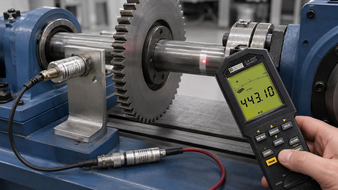
A fluctuating speed indication, sporadically missing pulses or brief overspeed alarms are often attributed prematurely to the controller or frequency counter. In many cases, however, the fault already originates at the mechanical interface between the speed sensor and the target wheel.
An excessively large or varying air gap, unsuitable tooth dimensions, runout or an exceeded maximum switching frequency can prevent individual teeth from being detected reliably. Electrical interference, incorrect PNP or NPN wiring or an excessively slow PLC input can additionally suppress pulses or generate double edges.
For reliable diagnosis, the target geometry, sensor technology, output signal, wiring and signal evaluation must therefore be considered together. A sensor may provide a clean signal on the test bench but still fail inside the machine if vibration, temperature, motor cables or the actual maximum speed have not been considered.
Suitable sensors and measuring instruments can be found in the ICS category Speed Sensors and Tachometers. Additional systems for displacement, force and motion measurement are grouped under Displacement, Force and Motion Sensors.
Table of Contents
- How is rotational speed calculated from pulses?
- Distinguishing between inductive, magnetic and optical sensors
- Distinguishing between passive and active inductive sensors
- Correctly setting the air gap
- Accounting for runout, bearing clearance and vibration
- Correctly designing the target wheel and tooth geometry
- Accounting for the target material
- Calculating the maximum switching frequency
- Why do faults frequently occur at low speed?
- How are double pulses generated?
- Distinguishing between PNP, NPN, push-pull and passive signals
- Correctly configuring the PLC input and frequency counter
- Correctly implementing shielding and cable routing
- Checking the signal with an oscilloscope
- Comparing the speed with a reference measurement
- Systematic diagnostic procedure
- Practical example: Missing pulses on a gear wheel
- Typical speed-sensor faults
- What should be included in the measurement documentation?
- Which products and solutions are suitable?
- Conclusion
- Frequently asked questions
How is rotational speed calculated from pulses?
A speed sensor generates a specific number of electrical pulses per revolution. With a gear wheel, the number of pulses normally corresponds to the number of teeth that are reliably detected.
The pulse frequency is:
f = n × z / 60
Where:
- f: pulse frequency in Hz,
- n: rotational speed in min−1,
- z: number of pulses or teeth per revolution.
Conversely, the rotational speed is calculated as:
n = 60 × f / z
A target wheel with 60 teeth already generates the following frequency at 6,000 min−1:
f = 6,000 × 60 / 60 = 6,000 Hz
A sensor or frequency input with a maximum rating of 5 kHz would not be sufficient for this combination. The permissible speed therefore depends not only on the sensor but also directly on the number of teeth.
The number of effective pulses must be entered correctly in the evaluation system. If a 48-tooth wheel is incorrectly configured as a 50-tooth wheel, the indication may be stable but will be systematically incorrect.
Distinguishing between inductive, magnetic and optical sensors
| Measuring principle | Suitable target | Typical strengths | Typical sources of error |
|---|---|---|---|
| Inductive proximity sensor | Metal teeth, cams or bores | Robust, non-contact, suitable for industrial use | Excessive air gap, unsuitable material, excessive switching frequency |
| Passive inductive pickup | Ferromagnetic gear wheel | Simple design; high temperature and vibration resistance possible | Insufficient signal amplitude at low speed |
| Hall or GMR sensor | Magnet, magnetised wheel or ferromagnetic target with an internal magnet | Detection down to near standstill, digital output signal | Incorrect magnet polarity, external magnetic fields, excessive air gap |
| Optical reflective sensor | Reflective marker or contrasting surface | Large working distance possible, no metallic target required | Oil, dust, external light, multiple reflective points |
| Fork light barrier | Perforated disc, slots or flags | Defined edges and high resolution | Contamination, disc wobble, mechanical collision |
The term “inductive speed sensor” is not unambiguous. It may refer either to an active inductive proximity switch or to a passive electromagnetic pickup. Both systems respond to metallic or ferromagnetic targets, but their behaviour at low speed and their electrical signal evaluation differ fundamentally.
Distinguishing between passive and active inductive sensors
Active inductive proximity sensor
An active sensor is electrically powered and switches its output when a suitable metal target enters its sensing range. In principle, it can also detect a tooth at standstill.
Important specifications include:
- nominal sensing distance and assured sensing distance,
- maximum switching frequency,
- minimum ON and OFF time,
- PNP, NPN or push-pull output,
- permissible output load,
- flush or non-flush installation.
Passive inductive pickup
A passive pickup typically contains a coil and a magnet. A passing ferromagnetic tooth changes the magnetic flux and generates an alternating output voltage.
The signal amplitude depends strongly on:
- rotational speed or rate of change,
- air gap,
- tooth shape and tooth size,
- magnetic properties of the target wheel,
- input impedance of the evaluation electronics.
At low speed, the signal can fall below the switching threshold of the evaluation system. A passive sensor may therefore operate perfectly at high speed but lose pulses during slow start-up.
The sinusoidal or pulse-like signal of a passive pickup must not be connected to an arbitrary digital PLC input without verification. A suitable signal conditioner with amplification, hysteresis and a defined switching threshold is often required.
Correctly setting the air gap
The air gap is the shortest distance between the active sensor surface and the highest point of the passing target. It must remain within the permissible sensor range throughout the complete revolution.
An excessively large air gap can cause:
- insufficient signal amplitude,
- unreliable switching points,
- failure to detect individual small or damaged teeth,
- high sensitivity to vibration and temperature.
An excessively small air gap, by contrast, increases the risk of mechanical contact caused by:
- target-wheel runout,
- bearing movement,
- shaft deflection,
- thermal expansion,
- vibration or shock loads,
- installation errors.
The nominal sensing distance of a proximity sensor is not automatically the recommended installation distance. Manufacturing tolerances, temperature, supply voltage and target material can reduce the actual assured sensing range.
The setting must therefore be based on the sensor data sheet while accounting for the complete mechanical tolerance chain.
Accounting for runout, bearing clearance and vibration
An air gap that is correctly set at standstill can change significantly during operation. Large gear wheels, long shafts, flexible couplings and sensor brackets with insufficient rigidity are particularly critical.
For assessment, the following simplified relationship applies:
Maximum air gap = installation distance + runout + bearing movement + deformation + vibration
At the same time, the minimum distance must remain sufficiently large to reliably prevent contact between the sensor and the target wheel.
A fluctuating air gap often appears on an oscilloscope as a periodic variation in signal amplitude. If the fault always occurs at the same angular position, the following should be inspected in particular:
- eccentric target wheel,
- deformed gear rim,
- individual damaged tooth,
- different tooth heights,
- shaft runout or bearing fault.
The sensor bracket must be sufficiently rigid, resistant to vibration and secured against rotation. A simple threaded nut may loosen in highly vibrating applications if the specified locking method is not used.
Correctly designing the target wheel and tooth geometry
Not every existing gear wheel is automatically suitable as a measuring wheel. The sensor must be able to distinguish clearly between the tooth and the tooth gap at every speed.
Important geometric characteristics include:
- tooth width in the direction of movement,
- width of the tooth gap,
- tooth height or difference in depth,
- target width across the sensor surface,
- edge shape and chamfers,
- surface condition,
- runout and pitch accuracy.
Both the tooth and the gap must remain in front of the sensor long enough for it to switch reliably on and off. Very narrow teeth may result in a mathematically permissible overall frequency, but generate pulses whose high or low time is shorter than the minimum pulse width of the sensor or evaluation input.
A large chamfer or rounded tooth edge creates a slow signal transition. With low signal amplitudes or electrical interference, the switching threshold may then be crossed several times.
For optical sensors, the reflective marker must:
- be sufficiently large,
- adhere securely,
- provide a clear contrast to the background,
- be located within the permissible distance,
- remain free from oil, dust and condensation.
Additional shiny screws, edges or markings can create further reflections and therefore double pulses.
Accounting for the target material
Passive magnetic-inductive pickups normally require a ferromagnetic target wheel. Aluminium, brass or non-magnetic grades of stainless steel may not generate a sufficient signal without a specially designed sensor.
The material also influences the usable sensing distance of active inductive proximity sensors. The nominal sensing distance is frequently determined using a specified standard steel target. Other metals may have a smaller effective sensing distance.
A coating, thick layer of paint or adhering metal debris can also change the switching behaviour. Metal chips on the sensor face can cause a permanent or irregular signal, particularly with magnetic sensors.
For Hall and GMR sensors, it must be clarified whether:
- an external magnet is required,
- the sensor has its own bias magnet,
- a specific magnet polarity is required,
- the target wheel must be ferromagnetic,
- the direction of rotation is detected using two phase-shifted channels.
Calculating the maximum switching frequency
The maximum sensor frequency must be higher than the highest expected pulse frequency. The same applies to the signal conditioner, frequency input, PLC counter and software evaluation.
The maximum possible rotational speed is calculated as:
nmax = 60 × fmax / z
Examples:
| Number of teeth | Maximum frequency | Calculated maximum speed |
|---|---|---|
| 1 pulse/revolution | 500 Hz | 30,000 min−1 |
| 30 teeth | 5,000 Hz | 10,000 min−1 |
| 60 teeth | 5,000 Hz | 5,000 min−1 |
| 60 teeth | 10,000 Hz | 10,000 min−1 |
| 120 teeth | 10,000 Hz | 5,000 min−1 |
The system should not be operated directly at the published frequency limit without a safety margin. The following must also be considered:
- maximum-speed tolerance,
- brief overspeed,
- temperature range,
- asymmetrical duty cycle,
- minimum input pulse width,
- active input filters,
- transmission rate of downstream signal conditioners.
Even a fast sensor is of no benefit if the PLC input used can process only a few hundred hertz.
Why do faults frequently occur at low speed?
With passive inductive pickups, the output voltage decreases as the speed is reduced. While the sensor may provide a signal of several volts at rated speed, only a few millivolts may be generated during slow start-up.
The evaluation system may then detect:
- individual teeth too late,
- only some of the teeth,
- varying edge positions,
- no movement at all.
Depending on the application, possible corrective measures include:
- a smaller permissible air gap,
- larger and more clearly defined teeth,
- a suitable signal amplifier,
- evaluation using a lower switching threshold with hysteresis,
- an active Hall, GMR or proximity sensor.
At very low pulse frequencies, the evaluation time used to calculate the rotational speed can also be relevant. If the frequency is counted over a short, fixed time window, large jumps occur at low speed. Measuring the period between two edges often provides better resolution in this range.
How are double pulses generated?
Double pulses can have mechanical, optical or electrical causes.
Typical mechanical causes include:
- two detectable edges on a wide or unfavourably shaped target,
- a bore, groove or screw head next to the actual tooth,
- severe target-wheel wobble,
- a vibrating sensor bracket,
- metal chips on the sensor or gear wheel.
Electrical causes include:
- ringing and overshoot on the signal cable,
- insufficient input hysteresis,
- an open or incorrectly sized pull-up resistor,
- interference from frequency converters or contactors,
- missing common reference between the sensor and evaluation system.
With optical sensors, two reflective markers, a shiny edge or a partially detached marker may generate additional pulses.
Software filtering alone may stabilise the indicated value but does not eliminate the cause. In an overspeed or position-monitoring application, unverified filters may also suppress relevant genuine pulses.
Distinguishing between PNP, NPN, push-pull and passive signals
| Output | Operating principle | Important note |
|---|---|---|
| PNP | Switches the output towards the positive supply voltage | The input requires a reference to 0 V |
| NPN | Switches the output towards 0 V | Requires a suitable load or a pull-up resistor to the positive supply |
| Push-pull | Actively drives the output high and low | Produces defined edges even at higher frequencies |
| Open collector | Switches only in one direction | The pull-up resistor and input voltage must be compatible |
| Passive inductive pickup | Generates a speed-dependent alternating voltage | Requires a suitable frequency input or signal conditioner |
Before connection, at least the following must be checked:
- supply voltage,
- pin assignment,
- output type,
- permissible output current,
- input thresholds of the evaluation system,
- common reference potential,
- maximum input frequency.
Without suitable wiring, an NPN sensor connected to an input designed exclusively for PNP may remain permanently low or provide undefined signals. A passive pickup can be loaded excessively by an unsuitable input circuit, which further reduces its signal amplitude.
Correctly configuring the PLC input and frequency counter
A standard digital PLC input is frequently evaluated cyclically by the user program. Short pulses may occur entirely between two program cycles.
Fast speed signals therefore typically require:
- a high-speed counter input,
- a hardware frequency counter,
- a capture or interrupt function,
- a suitable frequency transmitter.
The following parameters must also be checked:
- maximum input frequency,
- minimum high and low time,
- digital input filter time,
- rising- or falling-edge selection,
- pulses per revolution,
- measuring window and averaging,
- standstill timeout,
- overspeed and underspeed limits.
An input filter of 5 ms, for example, suppresses pulses that are shorter than this period. At 100 Hz and a duty cycle of 50%, the high time is already only 5 ms.
For fast speed measurement, it is therefore not sufficient to consider only the nominal frequency limit. The required pulse width must also be compatible with the filter and input configuration.
Correctly implementing shielding and cable routing
Speed signals are frequently transmitted in the immediate vicinity of motor cables, frequency converters, contactors and solenoid valves. Passive sensor signals with low amplitudes are particularly susceptible to interference.
Suitable measures include:
- using a shielded and preferably twisted signal cable,
- separating the signal cable spatially from motor and power cables,
- crossing power cables at right angles where possible,
- adequately decoupling the sensor supply,
- clearly routing signal and supply potentials,
- connecting the shield in accordance with the manufacturer’s and system earthing concept,
- preventing operating current from flowing through the cable shield,
- accounting for metallic sensor brackets and machine potential.
A universal rule that the shield must always be connected at only one end or always at both ends is not correct for every application. With high-frequency interference, a large-area shield connection at both ends may be required. Where potential differences are present, however, equalising currents and the earthing concept must be considered.
For long cables, the cable capacitance, output driver and, where necessary, differential signal transmission must also be checked.
Checking the signal with an oscilloscope
A speed indication alone does not show why pulses are missing. An oscilloscope makes the waveform and timing visible.
Measurements should be taken:
- directly at the sensor,
- at the end of the cable,
- at the input of the PLC or frequency counter,
- where applicable, on the sensor supply voltage.
The following should be assessed:
- high and low levels,
- amplitude at minimum and maximum speed,
- rise and fall time,
- minimum pulse width,
- duty cycle,
- noise and interference pulses,
- overshoot and multiple edges,
- periodic amplitude variations caused by runout.
Trigger recording is suitable for rare faults. The trigger can be set to respond to an excessively short pulse, a missing pulse interval or an unusual amplitude.
The measuring instrument and probe must be suitable for the voltage and system environment. When measuring non-isolated systems, particular attention must be paid to the oscilloscope ground connection.
Comparing the speed with a reference measurement
An independent speed measurement helps distinguish between an actual speed fluctuation and a pulse-detection error.
Suitable reference methods include:
- an optical tachometer with a single reflective marker,
- a contact tachometer on an accessible shaft,
- a stroboscope,
- a second independently operating sensor,
- an encoder or machine signal with known accuracy.
With an optical measurement using one reflective marker, one pulse corresponds to one revolution. Several reflective points, however, produce an integer multiple of the actual rotational speed.
A stroboscope can also produce ambiguous results. An apparently stationary image can occur at the actual rotational speed, but also at an integer fraction or multiple of it. The setting must therefore be approached using different flash frequencies.
Systematic diagnostic procedure
- Document the fault pattern: Record whether it occurs during start-up, at rated speed, after warming up, during load changes or under vibration.
- Check the pulse count: Determine the actual number of teeth, magnets or reflective markers.
- Calculate the frequency: Determine the highest and lowest pulse frequency from the speed and number of pulses.
- Compare the limits: Check the sensor, signal conditioner and evaluation input for frequency and minimum pulse width.
- Inspect the target wheel: Check the teeth, gaps, runout, material and contamination.
- Measure the air gap: Record the minimum and maximum distance over one complete revolution.
- Inspect the sensor bracket: Check its rigidity, alignment and vibration behaviour.
- Check the electrical connection: Verify the supply, PNP/NPN/push-pull configuration, pin assignment and reference potential.
- Check the input parameters: Document the hardware counter, filter time, edge and scaling.
- Record the signal: Perform oscilloscope measurements at minimum, medium and maximum speed.
- Switch interference sources: Investigate the influence of frequency converters, contactors and solenoid valves.
- Take a reference measurement: Confirm the rotational speed independently using an optical or mechanical method.
- Make individual changes: After every correction, test the effect under identical operating conditions.
Practical example: Missing pulses on a gear wheel
On a test bench, the speed of a drive is measured using a gear wheel with 48 teeth. The maximum rotational speed is 7,200 min−1. At high speeds, the indicated value occasionally drops and subsequently returns to the expected value.
The required frequency is:
f = 7,200 × 48 / 60 = 5,760 Hz
The inspection identifies the following causes:
- The existing frequency input is specified only up to 5 kHz.
- An additional activated input filter increases the required minimum pulse width.
- The air gap varies because of target-wheel runout.
- The signal cable is routed parallel to the motor cable for several metres.
The sensor is replaced with a version featuring an active push-pull output and a suitable frequency range. The signal is connected to a sufficiently fast counter input. The sensor bracket is reinforced, the air gap is adjusted over one complete revolution and the signal cable is routed separately from the motor cable.
The subsequent oscilloscope measurement shows clearly defined high and low levels throughout the complete speed range. The optical reference measurement and pulse evaluation then agree.
The example demonstrates that the pulse loss was caused not by one individual fault but by a combination of the frequency limit, air-gap tolerance and cable routing.
Typical speed-sensor faults
| Error | Possible consequence | Suitable corrective action |
|---|---|---|
| Maximum frequency assessed without considering the number of teeth | The sensor is operated above its limit at high speed | Calculate the frequency from the rotational speed and pulse count |
| Air gap set at only one position while stationary | Runout causes periodic pulse losses | Check the distance over one complete revolution |
| Passive sensor connected directly to a standard PLC input | Missing pulses at low speed | Use a suitable signal conditioner or frequency input |
| PNP and NPN output confused | Permanent or undefined input signal | Match the output type to the PLC input |
| Standard PLC input used instead of a hardware counter | Short pulses are missed between program cycles | Use a high-speed counter or frequency module |
| Input filter set too long | Valid pulses are suppressed | Define the filter time on the basis of the minimum pulse width |
| Unsuitable target material | Insufficient sensing distance or no signal | Check the sensor’s target-material requirements |
| Sensor bracket vibrates | The air gap and switching point change dynamically | Reinforce the bracket and secure it against loosening |
| Reflective marker partially detached | Multiple pulses or signal dropouts | Replace the marker and prepare the surface correctly |
| Signal cable routed parallel to the motor cable | Interference pulses and fluctuating indication | Provide separate, shielded cable routing |
| Shield connected without an earthing concept | Interference or equalising currents | Observe the manufacturer’s and system requirements for shield connection |
| Only the smoothed speed indication checked | Missing pulses remain concealed by averaging | Record the raw signal and pulse intervals |
What should be included in the measurement documentation?
Traceable documentation should include at least:
- the system, shaft and measuring point,
- sensor type and serial number,
- measuring principle and output type,
- supply voltage,
- target-wheel material and number of teeth,
- tooth width, tooth gap and tooth height,
- configured air gap,
- measured runout,
- minimum and maximum speed range,
- calculated frequency range,
- maximum sensor and input frequency,
- minimum pulse width,
- cable type, length and shield connection,
- PLC or frequency input used,
- input filter and edge evaluation,
- oscilloscope images at low and high speed,
- result of the independent reference measurement,
- modifications performed and final test.
Photographs of the sensor position and target wheel facilitate subsequent comparative measurements. For safety-related overspeed monitoring, the complete tripping chain, test intervals and prescribed functional tests must also be documented.
Which products and solutions are suitable?
HySense RS500 inductive pickup
The HySense RS500 is an inductive speed or frequency sensor with an active push-pull output.
The frequency range extends from approximately 1 to 10,000 Hz. The active output stage generates defined signal levels and facilitates transmission to suitable frequency inputs and Hydrotechnik measuring systems.
The robust aluminium housing has an IP67 degree of protection. The supply voltage is 8 to 30 V DC. Before use, the tooth geometry, material, air gap and compatibility of the downstream input must be checked.
HySense RS5xx
The HySense RS5xx series includes different inductive frequency sensors.
The RS500 and RS506 cover frequencies up to 10,000 Hz. The RS510 is designed for a range up to 5,000 Hz. The sensors have an M14 × 1 mechanical connection and are designed for industrial speed and frequency measurements.
The selected version must be suitable for the required output type, measuring accuracy, temperature and measuring-instrument connection.
HySense RS300 and RS310
The HySense RS300 and RS310 sensors operate according to the GMR principle and cover a frequency range from 0.5 to 1,800 Hz.
They are suitable for magnetic or ferromagnetic target systems requiring a stable frequency output even in the lower speed range. The target wheel, magnet arrangement and connection must be matched to the particular version.
HySense RS100 optical speed sensor
The HySense RS100 detects reflective markers using visible red light. With standard reflectors, the specified range is up to 500 mm.
The maximum signal repetition frequency is 500 Hz. With one reflective marker per revolution, this corresponds mathematically to speeds of up to 30,000 min−1. If several markers are used, the permissible maximum speed is reduced accordingly.
HySense SC100 frequency signal conditioner
The HySense SC100 processes frequency signals up to 5,000 Hz and provides, among other options, a 4–20 mA output signal.
It is suitable where a frequency signal must be converted into a standard signal for an analogue PLC input, display or process recording. The maximum tooth frequency must not exceed the input range of the converter.
C.A 1727 tachometer
The C.A 1727 supports optical and contact speed measurements up to 100,000 min−1.
The instrument additionally provides frequency, period and event measurements as well as memory and a USB interface. It is particularly suitable as an independent reference when troubleshooting permanently installed speed sensors.
ICS Schneider Messtechnik provides support in selecting the sensor technology, frequency range, target wheel, air gap, signal conditioner and evaluation instrument, as well as in assembling complete measuring chains for motors, turbines, conveyor systems and test benches.
Conclusion
Missing or double speed pulses frequently originate not in the software but at the interface between the sensor, target and electrical evaluation system.
The required switching frequency is determined by the rotational speed and the number of pulses per revolution. Even at moderate speeds, a high-resolution target wheel can generate several kilohertz and exceed the frequency limit of the sensor, signal conditioner or PLC input.
The air gap must be assessed over one complete revolution. Runout, bearing movement, vibration and thermal expansion must cause neither signal loss nor mechanical contact.
The tooth material, width, gap and edge shape must be compatible with the measuring principle. Passive inductive pickups can produce insufficient signals particularly at low speed, while active sensors are primarily limited by their switching frequency and minimum pulse width.
PNP, NPN, push-pull and passive output signals require different input circuits. A fast sensor must not be evaluated using a slow standard PLC input.
The most reliable diagnosis combines mechanical inspection, frequency calculation, oscilloscope recording and an independent reference measurement. Modifications should be made individually and verified under identical operating conditions.
Frequently asked questions about missing pulses from speed sensors
Why does the sensor lose pulses only at high speed?
The maximum switching frequency of the sensor or input is frequently exceeded. In addition, pulses that are too short may be suppressed by an input filter.
How do I calculate the frequency of a gear wheel?
Multiply the rotational speed in min−1 by the number of teeth and divide the result by 60. At 3,000 min−1 and 60 teeth, the frequency is 3,000 Hz.
Why does a passive inductive sensor not work at low speed?
Its output voltage depends on the rate of change of the magnetic field. As the rotational speed decreases, the signal amplitude can fall below the detection threshold.
Can the air gap be set as small as possible?
Not without accounting for runout, bearing movement, vibration and thermal expansion. An excessively small distance can cause a collision between the sensor and target wheel.
Why are double pulses generated on one tooth?
Possible causes include unfavourable tooth edges, vibration, electrical overshoot, insufficient hysteresis or a second optical reflection point.
What is the difference between PNP and NPN?
A PNP output switches the positive supply voltage to the input. An NPN output switches the input to 0 V. The sensor and evaluation system must be electrically compatible.
What does a push-pull output mean?
The output is actively driven high and low. This produces defined edges without relying solely on an external pull-up or pull-down resistor to establish the signal level.
May the speed signal be connected to a standard PLC input?
Only if the frequency and pulse width remain within its specifications. A hardware counter or high-speed input is normally required for fast signals.
Why does the indicated speed fluctuate even though the actual speed is constant?
Possible causes include missing pulses, double edges, an incorrect pulse factor, target-wheel runout or unsuitable calculation and averaging times.
How can I determine whether the sensor or controller is causing the fault?
First check the signal directly at the sensor and then at the controller input using an oscilloscope. An independent optical speed measurement confirms the actual rotational speed.
Can a longer filter time stabilise the measurement?
It can suppress short interference pulses, but may also remove valid speed pulses. The filter time must be shorter than the relevant high and low times.
Which sensor is suitable for very low rotational speeds?
Active Hall, GMR or inductive proximity sensors are frequently more suitable than passive inductive pickups. The specific selection depends on the target, air gap, environment and output signal.