


A fill level of 50 % in a horizontal cylindrical tank actually corresponds to 50 % of the tank volume. However, at 25 % fill height, the tank does not contain 25 % of its volume. In an ideal horizontal cylinder with flat ends, it contains only around 19,55 %. At 75 % fill height, on the other hand, approximately 80,45 % of the volume has already been reached.
The reason for this is the circular cross-sectional area of the tank. Near the bottom, the liquid volume initially increases slowly, considerably faster in the middle section, and then more slowly again near the top of the tank. A simple linear conversion of fill height or 4 … 20 mA into liters therefore leads to systematic errors.
For a correct volume display, tank geometry, actual internal dimensions, installation position, measuring range and linearization characteristic must match. For tanks with dished heads, curved end sections, internal fittings or inclination, the simple cylinder formula is often no longer sufficient. In such cases, a tank table or a custom characteristic curve is usually the better basis.
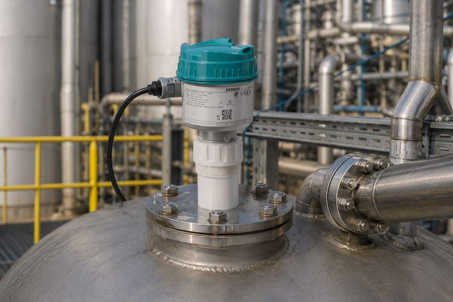
Suitable solutions are available from ICS Schneider under Level Measurement Technology. For non-contact continuous measurements, for example, the Siemens SITRANS Probe LU240 can be used. The device operates with ultrasound, features 4 … 20 mA/HART and, depending on the device version and parameterization, supports processing of level or volume.
Table of Contents
- Why fill height and tank volume are not proportional
- Geometry of a horizontal cylindrical tank
- Calculate the volume of a horizontal cylinder from the fill height
- Calculation example for a 2 m tank
- Why 25 % fill height does not mean 25 % volume
- What variable does the level sensor actually measure?
- 4–20 mA: transmit level or volume?
- Where should tank linearization take place?
- Use tank tables and breakpoints correctly
- Curved tank ends and special geometries
- Why an inclined tank can be problematic
- Correctly define the measuring point and sensor installation
- Influence of the medium on level measurement
- How tank geometry influences liter resolution
- Zero point, full point and usable volume
- Separate measured value and overfill protection
- Typical errors in tank linearization
- Systematically commission tank measurement
- Practical example: convert 4–20 mA to liters
- SITRANS Probe LU240 at ICS Schneider
- Conclusion
- FAQ
Why fill height and tank volume are not proportional
For a vertical cylinder with a constant cross-section, the situation is simple. If the fill height doubles, the liquid volume also doubles.
For a vertical cylinder:
V = A × h
Since the base area A remains constant, there is a linear relationship between fill height and volume.
In a horizontal cylinder, however, the width of the liquid surface changes with the fill height.
At the very bottom of the tank, the available cross-sectional width is very small. It reaches its maximum in the middle of the tank. Toward the top of the tank, it decreases again.
This results in an S-shaped characteristic between:
fill height → volume
A linear percentage display of the fill level is therefore not automatically a linear percentage display of the tank contents.
Geometry of a horizontal cylindrical tank
For an ideal horizontal cylinder, three variables are initially required:
- internal tank diameter
D, - internal radius
R = D / 2, - internal cylindrical length
L.
The fill height:
h
is measured from the lowest internal point of the cylinder to the liquid surface.
For the calculation:
0 ≤ h ≤ 2R
Use internal dimensions instead of external dimensions
A common error is to use the external diameter of the tank from a drawing or nameplate.
For the geometric volume calculation, however, the actual available internal volume is decisive.
If applicable, the following must be taken into account:
- wall thickness,
- internal coatings,
- tank linings,
- welded internal components,
- heating coils,
- displacement bodies.
The geometric calculation should therefore preferably be based on a tank drawing or a tank table provided by the manufacturer.
Calculate the volume of a horizontal cylinder from the fill height
For an ideal horizontal cylinder with flat ends, the filled circular segment area must first be calculated.
For the radius:
R = D / 2
and the fill height h:
A(h) = R² × arccos((R - h) / R) - (R - h) × √(2Rh - h²)
The volume is then calculated as:
V(h) = A(h) × L
Where:
A(h)= filled cross-sectional area,R= internal tank radius,h= fill height from the tank bottom,L= internal length of the cylindrical tank section,V(h)= liquid volume.
Total volume of the ideal cylinder
At full filling:
Vmax = π × R² × L
The volume fill percentage can then be calculated as:
Volume % = V(h) / Vmax × 100
These equations are exact only for a horizontal cylinder with a constant cross-section and the end geometries included in the calculation.
Calculation example for a 2 m tank
A horizontal cylindrical tank has the following internal dimensions:
D = 2,00 m
R = 1,00 m
L = 4,00 m
The theoretical total volume of the cylindrical tank is:
Vmax = π × 1² × 4
Vmax ≈ 12,566 m³
or:
≈ 12.566 liters
Fill height 0,50 m
The liquid level is therefore at:
25 % of the tank height
However, the circular segment calculation gives only approximately:
19,55 % of the tank volume
This corresponds to:
≈ 2.457 liters
Fill height 1,00 m
The tank is filled exactly up to the cylinder axis.
Therefore:
50 % fill height = 50 % volume
The volume is:
≈ 6.283 liters
Fill height 1,50 m
The fill height is:
75 %
However, the actual volume is already:
≈ 80,45 %
or:
≈ 10.110 liters
Why 25 % fill height does not mean 25 % volume
| Fill height relative to tank diameter | Volume fraction for an ideal horizontal cylinder |
|---|---|
| 10 % | approx. 5,20 % |
| 25 % | approx. 19,55 % |
| 50 % | 50,00 % |
| 75 % | approx. 80,45 % |
| 90 % | approx. 94,80 % |
| 100 % | 100,00 % |
The symmetry of the circular cross-section means that 50 % fill height also corresponds to 50 % volume.
Below and above this point, however, the characteristic is distinctly nonlinear.
The greatest volume increase per millimeter occurs in the middle of the tank
Near the middle of the tank, the horizontal liquid cross-section is widest.
An additional millimeter of fill height therefore corresponds to more liters there than an additional millimeter directly above the tank bottom or shortly before the tank top.
This also affects the practical measurement uncertainty.
What variable does the level sensor actually measure?
Before configuring a display in liters, it must be clear which physical variable the sensor actually provides.
Ultrasonic and radar
Non-contact sensors typically first measure a distance between the sensor and the product surface.
From:
distance
and the known tank geometry:
fill height
is calculated.
Only then can the fill height be converted into a volume.
Hydrostatic level measurement
A hydrostatic measurement, on the other hand, determines the pressure generated by the liquid column.
In simplified form:
p = ρ × g × h
This gives:
h = p / (ρ × g)
Here, the density ρ directly influences the calculated fill height.
Float and magnetostrictive systems
These typically detect the position of the liquid surface directly.
Here too, the result is initially height information. The geometric conversion to liters remains necessary for a horizontal cylindrical tank.
4–20 mA: transmit level or volume?
A 4 … 20 mA signal does not inherently contain information about whether it represents:
- distance,
- fill height,
- percentage fill level,
- liters,
- cubic meters.
This is determined exclusively by the parameterization.
Variant 1: 4–20 mA corresponds linearly to fill height
Assume:
4 mA = 0 mm
20 mA = 2.000 mm
The fill height can then be calculated from the current:
h = (I - 4 mA) / 16 mA × 2.000 mm
A signal of:
8 mA
therefore corresponds to:
25 % fill height = 500 mm
In a horizontal cylinder, however, this 25 % fill height corresponds to only around:
19,55 % volume
In this case, a PLC must therefore not simply calculate:
8 mA → 25 % → 25 % tank volume
.
Variant 2: 4–20 mA already corresponds to the linearized volume
If the tank geometry is already processed in the level measuring instrument and the volume is output as the process value, the following may apply, for example:
4 mA = 0 liters
20 mA = 12.566 liters
The current-to-volume relationship at the output is then linear:
V = (I - 4 mA) / 16 mA × Vmax
Before any PLC scaling, it must therefore be clarified whether the current signal represents the raw fill level or the already linearized volume.
Where should tank linearization take place?
In principle, the conversion from fill height to volume can take place at different points.
In the level measuring instrument
A suitably equipped transmitter can internally account for a known tank geometry and directly generate a volume-related process value.
Advantages may include:
- uniform parameterization directly at the measuring point,
- volume value available via HART or digital communication,
- potentially volume-linear
4 … 20 mAsignal.
In the PLC
Alternatively, the fill level can be transmitted linearly and the PLC performs the conversion.
This is often useful when:
- a tank table is already available,
- several tanks are evaluated centrally,
- complex special geometries are present,
- an existing plant control system manages the linearization.
In the process control system or HMI
A conversion solely for display purposes is also possible. However, it should be documented precisely which upstream systems continue to work with fill height and which already work with volume.
Otherwise, different readings may occur within the same plant.
Use tank tables and breakpoints correctly
For real tanks, a tank table prepared by the manufacturer is often more reliable than a simplified geometric calculation.
A typical table may contain, for example:
| Fill height | Volume |
|---|---|
| 0 mm | 0 l |
| 100 mm | … |
| 200 mm | … |
| 300 mm | … |
| … | … |
| 2.000 mm | … |
The evaluation system can interpolate between the points.
Place breakpoints more densely where the characteristic is more strongly curved
With piecewise linear approximation, the number and distribution of breakpoints determine the deviation from the actual tank characteristic.
Uniform distribution is not always optimal.
Additional breakpoints are particularly useful:
- at transitions between the cylinder and tank end,
- in strongly curved tank sections,
- at geometry discontinuities,
- at structural internal components.
If an official dip table or calibration table for the tank is available, it should normally take precedence over a characteristic calculated from approximate external dimensions.
Curved tank ends and special geometries
Many industrial storage tanks do not consist of a simple pipe with two flat end plates.
Common designs include, for example:
- torispherical heads,
- dished heads,
- elliptical ends,
- parabolic ends,
- conical sections,
- combined geometries.
The total volume then consists of several geometric sections.
The simple formula:
V(h) = circular segment × cylinder length
does not correctly represent these additional volumes.
The end regions are particularly critical
With curved end sections, the cross-sectional profile changes along the tank axis.
The amount of liquid at a certain fill height then depends not only on the radius and cylinder length, but also on the exact geometry of the tank ends.
In this case, one of the following should be used:
- a suitable predefined tank shape in the measuring instrument,
- a manufacturer tank table,
- a custom characteristic curve.
Why an inclined tank can be problematic
The standard calculation for a horizontal cylinder assumes that its longitudinal axis is exactly horizontal.
If the tank is inclined, the liquid surface remains horizontal while the tank bottom rises or falls along the tank axis.
A single level measuring point then no longer represents the same local fill height everywhere in the tank.
Even small inclinations can be relevant for long tanks
If there is a height difference between the two tank ends, the volume relationship changes particularly when the tank is almost empty or almost full.
For demanding volume determination applications, it should therefore be checked:
- whether the tank is actually horizontal,
- where the sensor is located along the tank axis,
- whether an existing tank table was created in the installed condition,
- whether the plant has changed due to foundation settlement or modifications.
Correctly define the measuring point and sensor installation
A mathematically perfect linearization cannot correct an improperly installed level sensor.
For non-contact measurement
the following should be checked, among other things:
- clear view of the product surface,
- sufficient distance from the tank wall and internal components,
- no interfering pipes within the acoustic or measuring cone,
- installation not directly above an inlet or strong turbulence,
- correct alignment toward the surface,
- permissible near range or required distance from the maximum fill level.
Clearly define the measurement reference
The software requires an unambiguous relationship between:
measured distance
and:
actual fill height
Factors such as mounting nozzles, sensor position and geometric zero point must be correctly taken into account.
An error of several centimeters in the geometric zero point is not eliminated by the tank linearization. Instead, it is converted into an incorrect liter value.
Influence of the medium on level measurement
The geometric relationship between fill height and volume is initially independent of whether the tank contains water, oil or another medium.
However, the measurement principle used can very much be influenced by the properties of the medium.
For ultrasonic measurement, relevant factors include
- foam formation,
- vapor and gas atmosphere,
- turbulence,
- temperature conditions,
- condensation on the sensor,
- interfering internal components.
For hydrostatic measurement, density is decisive
Since:
p = ρ × g × h
a change in density at the same fill height changes the measured hydrostatic pressure.
Temperature changes or changing media can therefore cause an additional error in the fill height calculated from the pressure.
For tank content calculations, also distinguish between
A display in liters initially describes a geometric liquid volume.
For mass or trade-related quantities, the following may additionally be required:
- density compensation,
- temperature compensation,
- product characteristics,
- legal metrology requirements where applicable.
How tank geometry influences liter resolution
With a linear height measuring instrument, the measurement uncertainty is initially often specified in millimeters.
When converted into liters, however, the same height error does not have the same significance throughout the entire tank.
In the middle of the tank, one millimeter corresponds to more volume
This relationship can be illustrated by the current width of the liquid surface.
Near the tank bottom, this width is small.
In the middle of the cylinder, it reaches approximately the tank diameter.
The same height difference therefore produces a considerably larger volume difference in the middle than near the bottom.
For volume measurement, a distinction must therefore be made between:
- accuracy of the height measurement
and:
- resulting volume uncertainty
.
A constant measurement deviation of, for example, ±5 mm does not lead to the same deviation in liters across the entire filling range of a horizontal cylindrical tank.
Zero point, full point and usable volume
Before linearization, it must be defined what should actually be regarded in the plant as:
0 liters
and:
100 %
.
Geometrically empty is not always operationally empty
For example, an unusable residual quantity may remain below an outlet pipe.
At least three quantities must then be distinguished:
- geometric total volume,
- actual liquid volume present,
- operationally usable volume.
The upper range may also be restricted
For operational or safety reasons, a tank may not be allowed to be filled up to its geometric top.
In that case:
100 % operating fill level
and:
100 % geometric tank volume
may represent different values.
This definition must be clearly established and documented before parameterization.
Separate measured value and overfill protection
A continuous level measurement provides a process value for display, inventory management or control.
A required overfill protection system, on the other hand, is a separate safety function.
The fact that a transmitter reports a level of, for example:
95 %
does not automatically mean that a prescribed or required point-level safety function is fulfilled.
Depending on the application, medium and legal requirements, separate components may be necessary, for example:
- independent point level sensor,
- separate shutdown,
- alarm contact,
- suitable safety evaluation.
Volume calculation and safety function must therefore be assessed separately during plant design.
Typical errors in tank linearization
| Observation | Possible cause | Recommended check |
|---|---|---|
| 50 % fill height is correct, but other values are not | Linear volume scaling used for a horizontal cylinder | Check tank geometry and characteristic curve |
| 25 % height shows 25 % volume | No cylinder linearization activated | Check whether 4–20 mA represents fill height or volume |
| Liter value is correct in the middle range but not at the bottom and top | Incorrect tank shape or end geometry | Compare tank drawing and tank table |
| Constant offset across the entire range | Incorrect zero point or sensor distance | Check installation height and reference point |
| Maximum value is incorrect | Incorrect tank volume or incorrect Upper Scaling Point | Compare internal volume and parameterization |
| Liter value differs after tank modification | Internal components or usable volume changed | Redetermine the tank characteristic |
| Deviation depends on filling direction | Turbulence, foam or unstable surface | Compare measured value with a calm surface |
| Value is correct at one tank end but not across the entire geometry | Tank is inclined | Measure tank alignment |
| PLC and local display show different liter values | Linearization is performed differently at two points | Document signal definition and scaling |
| Hydrostatic measurement changes with the product | Different liquid density | Check density and temperature of the medium |
| Individual sections of the tank table show jumps | Incorrect breakpoints or units | Check all height and volume points |
Systematically commission tank measurement
- Determine tank shape: Clearly identify horizontal cylinder, curved ends or special geometry.
- Record internal dimensions: Obtain diameter, length and, if applicable, end geometry from drawings.
- Check tank position: Ensure that the tank is sufficiently horizontal.
- Select measurement principle: Consider medium, pressure, temperature, foam, vapor and installation situation.
- Determine sensor position: Ensure a clear measuring path and correct reference point.
- Define zero point: Specify whether it represents geometrically empty or operationally empty.
- Define full point: Distinguish between geometric total volume and maximum permissible operating fill level.
- Define tank characteristic: Select predefined tank shape, geometric calculation or tank table.
- Check breakpoints: For custom characteristics, use sufficient points in nonlinear sections.
- Define the meaning of 4–20 mA: Clearly document whether the signal represents fill height or already linearized volume.
- Check PLC scaling: Do not apply a second incorrect linearization.
- Approach reference points: If possible, compare several known fill levels or volumes.
- Check point levels separately: Do not automatically treat the process measurement as a safety function.
- Document parameters: Record tank dimensions, characteristic curve, current scaling and units.
Practical example: convert 4–20 mA to liters
A horizontal tank has:
D = 2.000 mm
L = 4.000 mm
The sensor is parameterized so that:
4 mA = 0 mm fill height
20 mA = 2.000 mm fill height
The following is measured at the PLC input:
I = 8,0 mA
Step 1: Convert current into fill height
h = (8 - 4) / 16 × 2.000 mm
h = 500 mm
The linear level display would indicate:
25 %
Step 2: Linearize fill height using the tank characteristic
For an ideal horizontal cylinder, 500 mm with a diameter of 2.000 mm corresponds approximately to:
19,55 % volume
Step 3: Calculate volume
The total volume is approximately:
12.566 l
This gives:
V ≈ 12.566 l × 0,1955
V ≈ 2.457 l
What would happen with incorrect linear scaling?
A direct conversion of 25 % to the total volume would give:
12.566 l × 0,25 ≈ 3.142 l
The error would therefore be approximately:
685 l
even though the actual level sensor is measuring correctly.
This example shows that an incorrect liter value is not necessarily caused by an inaccurate sensor. Often, the tank geometry is simply configured incorrectly in the evaluation system.
SITRANS Probe LU240 at ICS Schneider
The Siemens SITRANS Probe LU240 is a compact ultrasonic level transmitter for continuous level measurement.
ICS Schneider specifies, among other things:
- measuring range
0,2 … 12 mdepending on the version, - process temperature
-40 … +85 °C, - output
4 … 20 mA/HART, - HART 7 communication,
- PVDF or ETFE sensors depending on the version,
- degree of protection
IP68, - Process Intelligence echo processing.
Volume linearization in the device
Siemens provides volume calculation for the SITRANS Probe LU240 using different tank shapes.
The configurable geometries include, among others:
- linear tanks,
- tanks with conical bottom,
- tanks with parabolic bottom,
- tanks with hemispherical bottom,
- cylindrical tanks,
- tanks with parabolic ends,
- spherical tanks.
Available volume units include:
m³,liters
.
Custom tank characteristic
If the actual tank shape cannot be represented adequately by a predefined geometry, Siemens supports a custom characteristic curve.
Up to:
32 breakpoints
can be used for the relationship between fill height and volume.
This is particularly useful for existing:
- manufacturer tank tables,
- special tanks,
- combined geometries.
Correctly parameterize 4–20 mA
With the LU240, the process variable for the current output can be defined. For a volume application, the following must therefore match:
- process variable,
- tank shape or characteristic curve,
- volume unit,
- lower range value,
- upper range value or scaling value.
If volume is configured as the process variable, the 4 … 20 mA signal can be scaled accordingly to the volume-related process value. If level is transmitted instead, the nonlinear conversion may need to be performed in the PLC or another evaluation device.
For the specific device version, the available functions must always be checked against the relevant Siemens documentation. Siemens specifies, for example, restrictions on process variable selection for one device version with a 3 m measuring range.
Conclusion
Reliable level measurement and a correct display in liters are two different tasks. The sensor must first correctly detect the liquid surface or fill height. Only then is this value converted into volume using the tank geometry.
A horizontal cylindrical tank is nonlinear
At 25 % fill height, an ideal horizontal cylinder contains only around 19,55 % of its total volume. At 75 % fill height, it already contains approximately 80,45 %.
4–20 mA must be clearly defined
The current signal can represent either the linear fill level or the already linearized volume. The PLC and transmitter must use the same definition.
Real tank geometries often require a tank table
Curved tank ends, internal components, inclination and special shapes can make a simple cylinder calculation unsuitable.
Sensor accuracy is not the same as volume accuracy
In a horizontal cylinder, the same height error causes different volume errors depending on the current fill level.
Measurement and safety functions must be considered separately
A continuous display in liters does not automatically replace a required independent point-level or overfill protection system.
For practical applications
Determine tank geometry → check internal dimensions and installation position → select measurement principle → clearly define zero and full point → decide whether fill height or volume is to be transmitted → configure the appropriate tank shape or tank table → check 4–20 mA scaling → compare several known filling points → assess point-level safety function separately → document tank characteristic and parameterization.
FAQ: Convert the level of a horizontal tank into liters
How do you calculate the contents of a horizontal cylindrical tank?
First, the area of the filled circular segment is calculated from the radius and fill height. This area is then multiplied by the tank length.
Which formula applies to a horizontal cylindrical tank?
For the filled cross-sectional area, A(h) = R² × arccos((R - h) / R) - (R - h) × √(2Rh - h²). The volume is calculated from V = A × L.
Why can I not simply convert the fill height percentage directly into liters?
Because the cross-section of a horizontal cylinder is not constant over its height. Therefore, the relationship between fill height and volume is nonlinear.
Does 25 % fill height also mean 25 % tank volume?
No. In an ideal horizontal cylinder, 25 % fill height corresponds to only approximately 19,55 % of the total volume.
Does 50 % fill height also mean 50 % volume?
Yes. Due to the symmetry of the circular cross-section, half the tank height corresponds exactly to half the volume in an ideal horizontal cylinder.
How much volume corresponds to 75 % fill height?
For an ideal horizontal cylinder, approximately 80,45 % of the total volume.
Why is the volume characteristic S-shaped?
The available tank width is initially small at the bottom, reaches its maximum in the middle and then decreases again. Therefore, the volume per millimeter of fill height changes across the tank range.
What does tank linearization mean?
Tank linearization refers to converting a measured fill height into the corresponding volume based on the actual tank geometry.
What is a tank table?
A tank table assigns corresponding volumes to defined fill heights. It can be calculated from the tank geometry or determined by calibration.
When should I use a tank table instead of a formula?
A tank table is often more suitable particularly for curved ends, special shapes, internal components, inclined tanks or existing manufacturer calibration tables.
Should I use the internal or external diameter?
The actual internal tank diameter is decisive for the volume calculation.
Can the wall thickness cause a relevant error?
Yes. For large tanks, even an incorrect assumption about the diameter can result in a significant deviation in the calculated total volume.
What happens with curved tank ends?
In that case, the simple formula for a cylinder with flat ends is no longer sufficient. The geometry of the end sections must also be taken into account.
What must be considered for an inclined horizontal tank?
The standard characteristic assumes a horizontal tank axis. If the tank is inclined, a single fill height can no longer describe the total volume using the same standard characteristic.
What does 4–20 mA mean in level measurement?
That depends on the parameterization. The signal can represent, for example, distance, fill height, percentage or an already linearized volume.
How do I calculate the fill level from 4–20 mA?
For linear scaling between hmin and hmax, h = hmin + (I - 4) / 16 × (hmax - hmin).
Can I then simply multiply the percentage value by the tank volume?
Only for a linear tank geometry or if the percentage value has already been volume-linearized. For a horizontal cylindrical tank, additional geometric linearization is required.
Can 4–20 mA directly represent liters?
Yes, if volume linearization is already performed in the measuring instrument and the current output is scaled to the volume-related process value.
Should linearization preferably take place in the sensor or in the PLC?
Both are possible. The decisive factors are the plant concept, existing tank tables, maintainability and clear documentation of the signal definition.
Can double linearization cause an error?
Yes. If the transmitter already generates a volume-linearized output and the PLC applies another tank characteristic, the resulting value will be incorrect.
Does liquid density influence the cylinder calculation?
It does not influence the purely geometric conversion from height to volume. However, in hydrostatic level measurement, density affects the determination of fill height from the measured pressure.
Does temperature influence tank volume?
Depending on the accuracy requirements, both thermal expansion of the tank and changes in the volume or density of the medium may be relevant.
Why do the sensor display and liter display sometimes not match?
For example, the sensor may correctly indicate 40 % fill height, while the liter display must show a different volume percentage due to the tank geometry. This is only incorrect if both displays are supposed to represent the same variable.
How do I verify tank linearization?
The best method is to compare several known fill heights or known volume points across the entire tank range with the indicated value.
Are empty and full points sufficient for verification?
No. An incorrect nonlinear characteristic can be correct at 0 % and 100 % and still produce significant errors in between.
Where is the volume deviation per millimeter particularly large?
In a horizontal cylinder, the volume increase per millimeter of fill height is greatest near the middle of the tank.
Can ultrasound be used for a horizontal cylindrical tank?
In principle, yes, provided that the medium, measuring range and installation situation are suitable for ultrasonic measurement. Converting the measured fill height into volume is a separate task.
What is the SITRANS Probe LU240?
The Siemens SITRANS Probe LU240 is a compact ultrasonic level transmitter for continuous level measurement.
What measuring range does the SITRANS Probe LU240 have?
ICS Schneider specifies a range of 0,2 … 12 m depending on the version.
What output does the SITRANS Probe LU240 have?
The level transmitter features 4 … 20 mA/HART.
Can the SITRANS Probe LU240 calculate volume?
Siemens provides volume calculation with various tank shapes and custom characteristic curves for corresponding device versions. The function of the specific device version must be checked against the relevant device documentation.
Can liters be used as a unit with the SITRANS Probe LU240?
Yes. Siemens parameterization includes liters as a volume unit.
Can a custom tank table be stored in the SITRANS Probe LU240?
Siemens supports up to 32 level/volume breakpoints for custom volume characteristics.
What degree of protection does the SITRANS Probe LU240 have?
ICS Schneider specifies IP68.
What temperature range does ICS specify for the SITRANS Probe LU240?
The specified process temperature range is -40 … +85 °C.
Where can I find the SITRANS Probe LU240 at ICS Schneider?
Further information can be found under SITRANS Probe LU240 at ICS Schneider.
Where can I find further level measurement technology?
An overview can be found under Level Measurement Technology at ICS Schneider.