


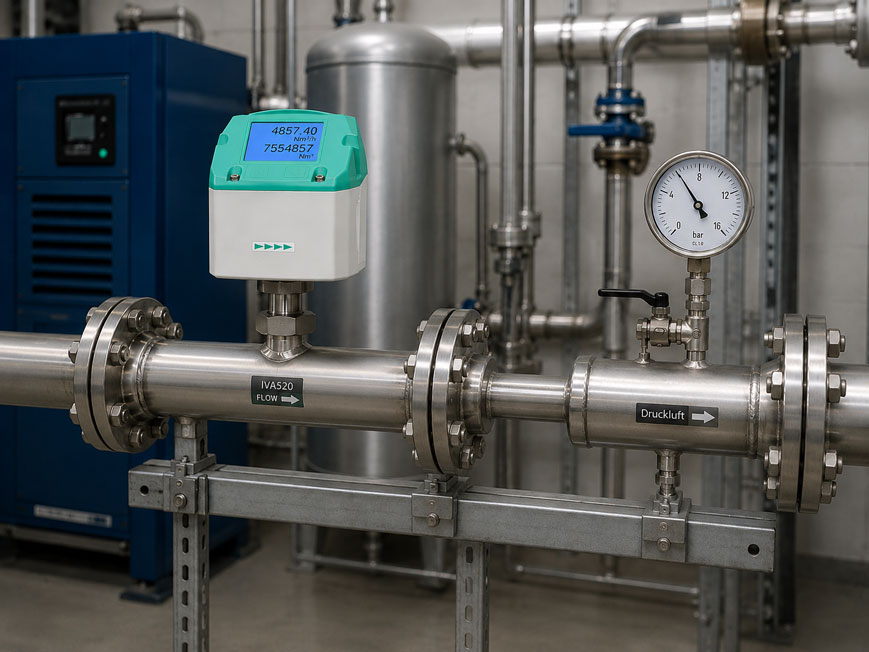
Compressed air consumption can only be evaluated unambiguously and compared between different measuring points if it is clearly defined which pressure and temperature conditions the stated volumetric flow rate refers to.
An indication of 500 m³/h therefore does not automatically answer the question of how much compressed air a consumer actually requires. The decisive factor is whether this refers to the actual volume of the compressed air in the pipeline or to a standard volume converted to defined reference conditions.
The difference is particularly significant in compressed air networks. Air at, for example, 7 bar gauge pressure occupies only a fraction of the volume in the pipeline that the same quantity of air would occupy after expansion to approximately atmospheric pressure.
For consumption balances, leakage assessments, cost-center metering and comparisons between compressor output and consumption, the same reference conditions must therefore always be used.
A particularly suitable measuring instrument is the IVA520 thermal mass flow sensor. The instrument measures mass flow and directly outputs the volumetric flow rate or total consumption referenced to defined conditions.
For retrofitting in existing larger pipelines, the IVA500 consumption sensor is also suitable. Further solutions can be found under consumption meters for gases and compressed air as well as in the complete range of flow measurement technology at ICS Schneider.
Table of Contents
- Why is m³/h not unambiguous for compressed air?
- What is operating volume?
- What is standard volume?
- Which standard conditions apply?
- Why must absolute pressure be used?
- Why does temperature affect the volume?
- Converting operating volume to standard volume
- Practical example: 100 m³/h at 7 bar gauge pressure
- How much do different reference conditions differ?
- Why thermal sensors measure mass flow
- Distinguishing flow rate and consumption
- Comparing compressor FAD and compressed air consumption
- Why reference conditions matter for energy costs
- What happens when network pressure fluctuates?
- What happens when gas temperature fluctuates?
- Distinguishing dry and wet compressed air
- Which measuring principle is suitable?
- Taking installation conditions into account correctly
- Why the actual pipe internal diameter matters
- Making measuring points throughout the plant comparable
- Practical example: apparently incorrect consumption after sensor replacement
- Typical fault patterns
- Recommended sizing and verification procedure
- Suitable compressed air consumption meters from ICS Schneider
- Conclusion
- FAQ
Why is m³/h not unambiguous for compressed air?
A cubic meter initially describes only a geometric volume.
For liquids, this is often relatively straightforward because their volume changes only slightly under typical process pressures.
Gases behave differently.
Compressed air is compressible.
The same mass of air can therefore occupy completely different volumes depending on pressure and temperature.
Example
If air is compressed from approximately atmospheric pressure to a significantly higher pressure, the air mass remains the same while its volume decreases considerably.
The specification:
100 m³/h
is therefore not sufficient without additional information.
It must be known whether the value refers to:
- the actual conditions in the pipeline,
- a defined standard condition,
- specific reference conditions of the measuring instrument
.
What is operating volume?
Operating volume describes the actual geometric gas volume under the current process conditions.
The most relevant factors are:
- operating pressure,
- gas temperature.
Example
A flow rate of:
100 m³/h operating volume
at:
7 bar(g)
describes the actual volume occupied per hour by the compressed air in the pipeline under these conditions.
If the same quantity of air is expanded to atmospheric pressure, it occupies a substantially larger volume.
Operating volume is frequently required for
- flow velocity in pipelines,
- pipeline sizing,
- pressure-loss calculations,
- sizing of certain volumetric flowmeters.
For comparing actual compressed air consumption, however, operating volume is often less practical because the value changes as soon as the network pressure changes.
What is standard volume?
With standard volume, the actual quantity of gas is mathematically converted to defined reference conditions.
The current pipeline pressure is therefore no longer the reference basis for the displayed volume.
Typical units are:
Nm³/h
for the instantaneous standard volumetric flow rate and:
Nm³
for accumulated standard consumption.
The major advantage
The same mass of air should always have the same standard-volume value under the same defined reference conditions, regardless of whether it is transported through the compressed air network at, for example:
6 bar(g)
or:
8 bar(g)
.
Standard volume is therefore particularly suitable for:
- compressed air consumption balances,
- cost-center metering,
- leakage assessment,
- energy management,
- comparison of different consumers,
- comparison of different production areas.
Which standard conditions apply?
The designation Nm³ alone should not be regarded as a complete definition of the reference conditions.
Different reference states are used in practice.
DIN 1343
A commonly used standard condition is:
TN = 0 °C = 273.15 K
and:
pN = 1,013.25 mbar absolute
Compressed air technology according to DIN 1945 or ISO 1217 reference conditions
Compressed air consumption meters also frequently use reference conditions of:
20 °C
and:
1,000 mbar absolute
.
With instruments such as the IVA520, corresponding reference conditions can be taken into account or configured.
This is crucial for comparisons
A measured value of:
1,000 m³
referenced to 20 °C and 1,000 mbar is not exactly the same gas condition as:
1,000 Nm³
referenced to 0 °C and 1,013.25 mbar.
For a consumption balance, therefore, not only the unit but also the configured reference temperature and reference pressure should be documented.
Why must absolute pressure be used?
For gas-state calculations, it is not the displayed gauge pressure that is decisive, but the absolute pressure.
A typical pressure gauge in a compressed air network may, for example, indicate:
7 bar(g)
.
This means approximately:
7 bar gauge pressure relative to the surroundings
At an ambient pressure of approximately 1 bar, the absolute pressure is:
pabs ≈ 8 bar(a)
In simplified terms
pabs = pg + pamb
If the conversion is accidentally calculated using:
7 bar
instead of:
8 bar absolute
a considerable systematic error is introduced.
Gauge pressure and absolute pressure must not be confused when converting gas volumetric flow rates.
Why does temperature affect the volume?
At the same pressure, a warmer quantity of gas occupies a larger volume than the same quantity of gas at a lower temperature.
For gas calculations, temperature must therefore be expressed as absolute temperature.
The conversion is:
T [K] = t [°C] + 273.15
Example
20 °C corresponds to:
293.15 K
0 °C corresponds to:
273.15 K
A calculation using:
20 / 0
is therefore physically incorrect.
Kelvin values must be used for volumetric-flow conversions.
Converting operating volume to standard volume
For an approximately ideal gas, the standard volumetric flow rate can be calculated from the operating volumetric flow rate.
In simplified form:
QN = QB · (pB / pN) · (TN / TB)
where:
QN= standard volumetric flow rate,QB= operating volumetric flow rate,pB= absolute operating pressure,pN= absolute reference pressure,TB= absolute operating temperature in Kelvin,TN= absolute reference temperature in Kelvin.
For higher accuracy requirements
the deviation of the real gas from ideal-gas behavior can additionally be taken into account using the compressibility factor:
QN = QB · (pB / pN) · (TN / TB) · (ZN / ZB)
In typical industrial compressed air applications, the required conversion is normally already handled internally by a suitable consumption meter.
Practical example: 100 m³/h at 7 bar gauge pressure
In a compressed air line, the actual measured flow rate is:
100 m³/h operating volume
.
The operating conditions are:
7 bar(g)
and:
20 °C
With approximately 1 bar atmospheric pressure:
pB ≈ 8 bar absolute
Reference: 20 °C and 1 bar absolute
Since the operating and reference temperatures are identical, the calculation can be simplified approximately to:
QN ≈ 100 · 8 / 1
and therefore:
QN ≈ 800 m³/h
on this reference basis.
Reference according to DIN 1343
At:
0 °C
and:
1,013.25 mbar absolute
the approximate result is:
QN ≈ 736 Nm³/h
The example demonstrates two important effects at the same time: the standard volumetric flow rate is significantly higher than the actual pipeline volume, and different reference conditions produce different standard-volume values.
How much do different reference conditions differ?
The differences may initially appear small, but they can become economically relevant when annual consumption volumes are large.
| Reference basis | Temperature | Absolute pressure | Result in the example |
|---|---|---|---|
| Operating condition | 20 °C | 8 bar(a) | 100 m³/h |
| Reference 20 °C / 1 bar | 20 °C | 1,000 mbar(a) | approx. 800 m³/h |
| DIN 1343 | 0 °C | 1,013.25 mbar(a) | approx. 736 Nm³/h |
In this example, the difference between the two reference volumetric flow rates is already approximately nine percent.
With annual consumption of several million cubic meters, different reference conditions can cause substantial discrepancies in consumption and cost statistics.
Why thermal sensors measure mass flow
Thermal consumption sensors such as the IVA500 or IVA520 essentially determine the gas mass flow.
The mass of air itself does not change through compression.
The measured mass flow can therefore be converted directly into a standardized volumetric flow rate using the defined density at the reference conditions.
This provides an important advantage
The user does not have to calculate the standard volumetric flow rate manually each time from:
- pipeline pressure,
- temperature,
- operating volume
.
The measuring system can directly provide values such as:
Nm³/h
or:
Nm³
.
Correct configuration nevertheless remains important
- correct gas type,
- correct reference conditions,
- correct unit.
Distinguishing flow rate and consumption
The terms flow rate and consumption are also frequently confused.
Instantaneous volumetric flow rate
A value such as:
500 Nm³/h
describes the instantaneous flow rate.
Total consumption
The meter integrates this flow over time.
The result may, for example, be:
2,500,000 Nm³
for a certain production period.
For cost-center metering
the integrated total consumption is usually the decisive value.
For:
- plant sizing,
- peak-load analysis,
- leak detection,
- detection of unusual operating conditions
the instantaneous standard volumetric flow rate is also important.
Comparing compressor FAD and compressed air consumption
Another common source of error arises when comparing compressor capacity with a compressed air consumption meter.
For compressors, the:
Free Air Delivery (FAD)
or delivery capacity is frequently specified with reference to defined intake conditions.
This value is not the same as the geometric volumetric flow rate of the compressed air in the pressure line.
Example
A compressor with a delivery capacity of approximately:
1,000 m³/h
referenced to atmospheric conditions does not transport 1,000 m³/h of geometric pipeline volume at, for example, 7 bar(g).
The actual volume of the compressed air is significantly smaller.
For a meaningful comparison
the compressor value and the consumption measurement must therefore be compared:
- on the same pressure basis,
- on the same temperature basis,
- using the same definition of gas quantity
.
Only then can, for example:
compressor delivery − measured consumers
be used to create a meaningful network balance.
Why reference conditions matter for energy costs
Compressed air is one of the comparatively expensive energy carriers in many industrial facilities.
Typical key figures include:
kWh/Nm³
or:
€/1,000 Nm³
An incorrect reference basis distorts these key figures
If the electrical energy consumed by the compressor is related to a consumption value calculated using different standard conditions than the reference value, a systematic error is introduced.
This affects, for example:
- compressor comparisons,
- site benchmarking,
- cost-center allocation,
- leakage costs,
- economic evaluation of efficiency measures.
The reference conditions should therefore be included in the documentation of a compressed air measuring point just like the measuring range, pipe diameter and gas type.
What happens when network pressure fluctuates?
Assume that a consumer requires approximately the same mass of air over a certain period.
However, the network pressure changes.
At higher pressure, the same mass of air occupies a smaller operating volume.
At lower pressure, the operating volume becomes larger.
A pure operating-volume measurement would therefore indicate different values
even though the actual mass of air consumed remains practically unchanged.
A standard volumetric flow rate referenced to constant conditions
remains comparable for the same quantity of gas.
This is precisely why standardized volumetric units have become established for compressed air consumption measurement.
What happens when gas temperature fluctuates?
A change in temperature also changes the operating volume.
At the same pressure, warm air occupies a larger volume than cold air.
This is relevant, for example
- directly downstream of a compressor,
- upstream and downstream of an aftercooler,
- in outdoor compressed air pipelines,
- where strong seasonal temperature fluctuations occur.
If only geometric volume is compared, differences can occur even though the mass flow is similar.
With standard-volume measurement, this temperature effect is converted back to the defined reference basis.
Distinguishing dry and wet compressed air
Pressure and temperature are not the only factors determining the choice of measuring system.
The moisture condition of the compressed air is also important.
Thermal mass flow sensors
are particularly suitable for gaseous media where no disruptive condensation occurs on the sensing element.
Measuring points can become problematic
if:
- liquid condensate is carried along,
- water droplets are present,
- the line is regularly wet.
Typical critical locations are directly downstream of:
- compressors without sufficient air treatment,
- aftercoolers,
- wet compressed air receivers.
For wet compressed air
a suitable differential-pressure measuring principle may be more appropriate.
ICS offers, for example, the IVD520 inline differential-pressure flow sensor for this purpose.
Which measuring principle is suitable?
| Measuring task | Typically suitable principle |
|---|---|
| Consumption measurement of dry compressed air | thermal mass flow |
| Retrofitting in an existing large pipeline | thermal insertion sensor |
| Defined inline measuring section | thermal inline sensor |
| Measurement directly at a machine consumer | compact inline consumption sensor |
| Wet compressed air | suitable differential-pressure measuring method |
| Very large pipe sizes | consider insertion, ultrasonic or another suitable measuring concept |
The decision should not be based solely on the maximum flow rate.
The following must also be taken into account:
- minimum flow,
- pressure,
- temperature,
- moisture,
- pipe diameter,
- flow direction,
- installation conditions.
Taking installation conditions into account correctly
Even a sensor correctly configured for Nm³/h can provide incorrect consumption values if it is installed incorrectly.
Upstream of a flow sensor, in particular
- pipe bends,
- T-pieces,
- reducers,
- valves,
- filters
can influence the flow profile.
Depending on the measuring principle, defined upstream and downstream straight lengths are therefore required.
With an insertion sensor
the following must additionally be taken into account:
- correct insertion depth,
- correct sensor orientation,
- actual pipe internal diameter.
An incorrect diameter can cause a direct systematic error in the volumetric-flow calculation.
Why the actual pipe internal diameter matters
An insertion sensor measures the flow velocity at a defined position in the pipe.
To determine volumetric flow, this velocity is related to the effective pipe cross-sectional area.
In simplified form:
Q = v · A
where:
Q= volumetric flow rate,v= flow velocity,A= pipe cross-sectional area.
The cross-sectional area is
A = π · d² / 4
The diameter therefore enters the cross-sectional-area calculation as a squared value.
An incorrect assumption regarding the internal diameter can therefore cause a noticeable measuring error.
Do not simply use the nominal diameter DN
The nominal size does not necessarily describe the exact actual internal diameter.
This depends, for example, on:
- pipe material,
- wall thickness,
- pipe series,
- coatings,
- deposits.
Making measuring points throughout the plant comparable
For energy monitoring, all compressed air consumption measuring points should be configured according to the same system.
The following should be documented consistently
- gas type,
- reference temperature,
- reference pressure,
- unit of the instantaneous value,
- unit of the totalizer,
- pipe internal diameter,
- measuring-point designation,
- flow direction.
Example
Measuring point A uses:
20 °C / 1,000 mbar
Measuring point B uses:
0 °C / 1,013.25 mbar
Both display a technically correct standardized volumetric flow rate.
However, their totalizer readings must not simply be compared without taking the different reference basis into account.
For a centralized compressed air balance, a uniform reference basis should therefore be defined for all measuring points.
Practical example: apparently incorrect consumption after sensor replacement
A production hall has had a compressed air consumption meter for several years.
Typical daily consumption is:
10,000 m³
After replacing the sensor, the new meter suddenly indicates:
9,200 m³
despite virtually unchanged production.
Initial suspicion
The new sensor is assumed to be measuring too low.
Mechanical inspection
Pipe diameter, installation position and measuring range are correct.
Checking the configuration
The old sensor used the following reference basis:
20 °C / 1,000 mbar
.
The new sensor, however, uses:
0 °C / 1,013.25 mbar
.
Cause
The two instruments indicate the same physical quantity of gas referenced to different conditions.
The difference is therefore not an actual measuring error.
Solution
The reference conditions of the new sensor are standardized according to the plant’s measuring standard.
In addition, the reference conditions of all consumption measuring points are documented.
The example shows why, when unexpected changes occur, not only calibration and sensor accuracy but also the standard-volume definition being used must be checked.
Typical fault patterns
| Observation | Possible cause | Recommended check |
|---|---|---|
| Consumption is approximately a factor of 7 to 9 too low | operating volume confused with standard volume | check pressure and reference conditions |
| Conversion is incorrect despite known operating pressure | gauge pressure used instead of absolute pressure | convert bar(g) to bar(a) |
| Measuring points differ by several percent | different reference temperatures | compare standard conditions |
| New meter indicates less than the old one | different reference basis configured | check reference pressure and reference temperature |
| Consumption changes significantly with network pressure | operating volume evaluated instead of standardized gas quantity | check measuring principle and unit |
| Annual balance does not match compressor delivery | different definitions or reference conditions | standardize FAD and consumption basis |
| Consumption measurement incorrect after pipe modification | pipe internal diameter or flow profile changed | check configuration and installation conditions |
| Insertion sensor continuously indicates too high or too low | incorrect insertion depth or pipe diameter | check mounting dimensions |
| Measurement directly downstream of compressor is unstable | wet compressed air, pulsations or high temperature | check measuring principle and measuring point |
| Consumption appears to decrease after pressure increase | operating volume is being considered | evaluate standardized gas quantity |
| Cost figure kWh/m³ changes after sensor replacement | meter reference conditions changed | compare unit and standard conditions |
| Meters from different manufacturers do not agree | different reference conditions or gas configuration | compare configurations completely |
| Consumption values are unexpectedly high at night | actual leaks or base consumption | evaluate load profile during production shutdown |
Recommended sizing and verification procedure
- Define the measuring objective: Specify instantaneous flow rate, total consumption or both.
- Determine the medium: Clearly specify compressed air or another gas.
- Clarify the condition of the compressed air: Distinguish between dry, humid or condensate-laden air.
- Determine minimum flow: Take leakage and partial-load operation into account.
- Determine maximum flow: Include production peaks.
- Specify operating pressure: Document minimum and maximum values.
- Clarify pressure type: Do not confuse gauge and absolute pressure.
- Determine gas temperature: Record the relevant operating range.
- Define the standard-volume basis: Specify reference temperature and reference pressure.
- Standardize the plant measuring standard: Use the same reference conditions for comparable measuring points.
- Determine pipe dimensions: Take the actual internal diameter into account.
- Select the measuring principle: Choose thermal, differential pressure or another suitable method.
- Select the measuring range: Take both partial load and peaks into account.
- Check the measuring point: Consider bends, T-pieces and valves.
- Observe inlet conditions: Follow the manufacturer’s requirements.
- Check installation direction: Mount the sensor according to the flow direction.
- Set insertion depth: For insertion sensors, install precisely according to the specification.
- Configure the gas type: Avoid incorrect gas density.
- Configure the reference conditions: Set the required standard basis.
- Check the unit: Clearly document m³/h, Nm³/h, l/min or another unit.
- Check the totalizer: Distinguish total consumption from instantaneous value.
- Perform a plausibility check: Compare the result with compressor or reference data.
- Document all measuring points: Include standard conditions in the energy-management system.
- Calibrate or verify regularly: Ensure long-term stability.
Suitable compressed air consumption meters from ICS Schneider
IVA520 – inline consumption meter for compressed air and gases
The IVA520 is a thermal mass flow sensor with an integrated measuring section for compressed air and various non-corrosive gases.
Key features include:
- measurement of mass flow and direct output of standard volumetric flow,
- integrated measuring section,
- integrated display,
- 4 … 20 mA, pulse and Modbus RTU as standard,
- additional interfaces optional,
- optional bidirectional measurement,
- pressure range up to 40 bar,
- temperature range -30 … +80 °C,
- pipe sizes from DN 8 to DN 80,
- no moving parts.
For compressed air consumption measurement, it is particularly important that the sensor measures mass flow and can directly output it as a standardized volumetric flow rate referenced to defined conditions.
IVA500 – consumption measurement for retrofitting
The IVA500 is a thermal insertion sensor and is particularly suitable for retrofitting existing compressed air pipelines.
ICS specifies, among other things:
- direct output of standard volumetric flow,
- installation via a ½” ball valve,
- installation under pressure possible,
- 4 … 20 mA, pulse and Modbus RTU,
- integrated display,
- DN 15 to DN 1000, larger dimensions on request,
- optional bidirectional measurement,
- pressure range up to 50 bar.
With this design, the pipe internal diameter, installation position and insertion depth must be taken into account particularly carefully.
IVA521 – compact measurement at the end consumer
The IVA521 is intended for compact inline measuring points, for example directly at machines or downstream of an air-service unit.
The instrument is particularly suitable where many individual compressed air consumers are to be integrated into an energy-monitoring system.
Depending on the configuration, the following are available, among other things:
- instantaneous flow rate,
- total consumption,
- temperature,
- 4–20 mA output,
- pulse output,
- Modbus RTU,
- additional optional communication interfaces.
IVD520 – for wet compressed air
For applications involving wet compressed air, the IVD520 is available.
The instrument operates according to the differential-pressure principle and provides, among other values:
- flow rate,
- total consumption,
- temperature,
- pressure.
This means that a suitable solution is also available for measuring points where a thermal sensing element would be problematic due to condensate.
Further instruments can be found under consumption meters for gases and compressed air at ICS Schneider.
Conclusion
For compressed air, a volumetric flow value is only unambiguous if its pressure and temperature reference conditions are known.
Operating volume describes the actual pipeline volume
It depends directly on the current pressure and gas temperature.
Standard volume makes gas consumption comparable
The actual quantity of gas is converted to defined reference conditions.
Nm³/h is not completely defined without reference conditions
In practice, for example, 0 °C and 1,013.25 mbar according to DIN 1343 or 20 °C and 1,000 mbar in compressed air technology are used as reference conditions.
Absolute pressure is required for calculations
At approximately 1 bar ambient pressure, 7 bar(g) corresponds to around 8 bar(a).
Temperature must be entered in Kelvin
Only then can the change in gas state be calculated correctly from a physical perspective.
Thermal mass flow sensors simplify consumption measurement
They measure the quantity of gas on a mass basis and can directly output the volumetric flow rate referenced to defined conditions.
All measuring points must use the same reference basis
Only then can cost centers, production-area consumption, leakage rates and compressor capacities be meaningfully compared.
For practical applications
Define the measuring objective → determine operating pressure and temperature → convert gauge pressure to absolute pressure → define the required standard conditions → determine gas type and moisture condition → select a suitable measuring principle → check pipe internal diameter and installation conditions → correctly configure the reference conditions in the sensor → distinguish instantaneous value and total consumption → document the reference basis → standardize all measuring points in the energy-monitoring system → regularly check plausibility and verify consumption values.
FAQ: Correctly Distinguishing Nm³/h and m³/h for Compressed Air
What does Nm³/h mean for compressed air?
Nm³/h describes a gas volumetric flow rate per hour referenced to defined standard or reference conditions.
What does m³/h mean for compressed air?
The unit alone is not always unambiguous. It can describe operating volume or a volumetric flow rate referenced to specific conditions. The instrument documentation and reference conditions must therefore be checked.
What is operating volume?
Operating volume is the actual geometric volume of the compressed air at the current pipeline pressure and temperature.
What is standard volume?
Standard volume is the quantity of gas converted to defined pressure and temperature conditions.
Why is the standard volumetric flow rate higher than the operating volumetric flow rate?
Because compressed air occupies a substantially larger volume after mathematical expansion to approximately atmospheric reference pressure.
How much standard volume corresponds to 1 m³ of compressed air at 7 bar gauge pressure?
At approximately 7 bar(g), or around 8 bar(a), 1 m³ of operating volume at the same temperature corresponds approximately to 8 m³ on a reference basis of 1 bar absolute. The exact conversion also depends on temperature and the standard conditions used.
Why must absolute pressure be used for the conversion?
Gas-state equations refer to pressure relative to absolute vacuum rather than gauge pressure relative to the atmosphere.
What is the difference between bar(g) and bar(a)?
bar(g) denotes gauge pressure relative to the atmosphere. bar(a) denotes absolute pressure relative to vacuum.
How is 7 bar(g) converted to bar(a)?
At approximately 1 bar atmospheric pressure, 7 bar(g) corresponds to approximately 8 bar(a).
Which temperature applies to a normal cubic meter?
This depends on the reference definition being used. DIN 1343 uses 0 °C. Certain compressed-air reference systems use 20 °C.
Which pressure applies according to DIN 1343?
The reference pressure is 1,013.25 mbar absolute.
Which reference conditions are frequently used with compressed air measuring instruments?
In addition to DIN 1343, reference conditions of 20 °C and 1,000 mbar absolute are also used according to the corresponding compressed-air reference basis.
Are 1,000 Nm³ according to DIN 1343 and 1,000 m³ at 20 °C and 1 bar the same quantity of air?
No. The different reference temperature and slightly different reference pressure result in measurable differences.
Why is the reference temperature so important?
Gas volume changes with absolute temperature. The same mass flow therefore results in different reference volumetric flow rates at different reference temperatures.
Why must calculations use Kelvin?
Gas-state equations require an absolute temperature scale. Celsius values therefore cannot be used directly in temperature ratios.
What is the simplified conversion formula?
For an approximately ideal gas, QN = QB × pB/pN × TN/TB, with pressures entered as absolute values and temperatures in Kelvin.
Does the compressibility factor need to be considered?
For higher accuracy requirements, deviations from ideal-gas behavior can be taken into account using the compressibility factor Z. In many typical compressed air applications, a suitable measuring system performs the required conversion automatically.
What does a thermal mass flow sensor measure?
It determines the mass flow of the gas and can calculate a standardized volumetric flow rate from it using defined reference conditions.
Does a thermal compressed air meter additionally require a pressure sensor?
For pure mass-flow or standard-volume measurement, thermal sensors typically do not require separate external pressure compensation. However, the specific instrument design and application must still be taken into account.
What is the difference between Nm³/h and Nm³?
Nm³/h is an instantaneous standard volumetric flow rate. Nm³ is the standard gas quantity accumulated over time or a consumption totalizer reading.
Which unit should be used for compressed air costs?
For consumption and cost comparisons, a uniformly defined standardized gas quantity such as Nm³ is particularly suitable.
Why do two compressed air meters not agree?
In addition to measurement deviations, different reference conditions, gas types, pipe diameters, installation conditions or configurations may be responsible.
Can a sensor configured according to DIN 1343 indicate a different value from one using ISO 1217 reference conditions?
Yes. Different reference temperatures and reference pressures alone result in different reference-volume values for the same gas mass.
Why should the standard basis of all measuring points be documented?
So that consumption values between production halls, machines, cost centers and compressors can be correctly compared and balanced.
What is FAD for a compressor?
FAD stands for Free Air Delivery and describes the compressor delivery rate referenced to defined intake or reference conditions. It must not be confused with the geometric volumetric flow rate of the compressed air in the pressure line.
Can I compare FAD directly with a compressed air meter?
Only if both values are referenced to compatible or identical conditions.
Which sensor is suitable for permanent compressed air consumption measurement?
The IVA520 has an integrated measuring section and directly outputs the standard volumetric flow rate.
Which sensor is suitable for retrofitting in larger pipelines?
The IVA500 is installed as an insertion sensor in existing compressed air pipelines via a ball valve.
Which sensor is suitable directly at machines?
The IVA521 is designed as a compact inline sensor, among other applications, for individual machine consumers.
Can a thermal sensor measure wet compressed air?
Condensate on the thermal sensing element can be problematic. A measuring method suitable for wet compressed air should therefore be used.
Which instrument is suitable for wet compressed air?
ICS offers, for example, the IVD520 inline differential-pressure flow sensor for wet compressed air.
Why is the pipe internal diameter important?
With certain measuring methods, the volumetric flow rate is calculated from flow velocity and pipe cross-section. An incorrectly entered internal diameter therefore causes a systematic measuring error.
Is the nominal diameter DN sufficient for configuration?
Not always. The actual internal diameter depends, among other things, on pipe material and wall thickness.
Where can I find further compressed air consumption meters?
Further solutions can be found under consumption meters for gases and compressed air at ICS Schneider.